Mustafa İnci1,*, Tuğçe Demirdelen1, Mehmet Tümay1
J. Electrical Systems 11-4 (2015): 367-375 Regular paper Fuzzy Logic Controlled DC-DC Converter Based Dynamic Voltage Restorer
JES Journal of Electrical Systems
This paper presents fuzzy logic controlled dc-dc boost converter based Dynamic Voltage Restorer (DVR) to compensate severe voltage sag problems in an electrical system. DVR absorbs real power from battery to compensate voltage sags in the system. This condition causes reduction in voltage magnitude of dc-link capacitor. Additionally, DVR requires large dc capacitors to compensate long and severe voltage sags in the system. In this study, dc-dc boost converter is connected to DVR for keeping dc link voltage constant. For this propose, a control algorithm based on Fuzzy Logic (FL) control is developed for dc-dc boost converter. The main contribution of this study is that Fuzzy Logic (FL) is firstly used to generate reference signal for PWM signals of dc-dc converter applied in DVR. FL is a very flexible controller which keeps the dc link voltage constant during voltage sag. The performance results of proposed study are verified with PSCAD/EMDTC.
Keywords: fuzzy logic; DVR; voltage sag; dc link voltage Article history: Received 13 September 2015, Received in revised form 16 October 2015, Accepted 18 November 2015
1. Introduction Voltage, current, frequency deviations and waveform distortions that cause equipment failure, economical loss and several negative effects are known as power quality problems. The most severe power quality problem in electrical systems is called as voltage sag. Voltage sag is a short duration reduction in the rms value of voltage. There are several custom power devices for voltage sag compensation. Among these devices, DVR is the most effective device to compensate this power quality problem.
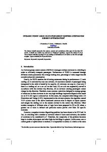
Figure 1. Conventional DVR
*
Corresponding author: M. İnci, Çukurova University, Electrical and Electronics Engineering, 01330, Adana, Turkey, E-mail:
[email protected] 1 Çukurova University, Electrical and Electronics Engineering, 01330, Adana, Turkey Copyright © JES 2015 on-line : journal/esrgroups.org/jes
M. İnci et al: Fuzzy Logic Controlled DC-DC Converter Based Dynamic Voltage Restorer
DVR is located between sensitive load and grid in system, as shown in Figure 1. The basic structure of a conventional DVR consists of an inverter, dc-link capacitor, filter and injection transformer[1-6]. The function of DVR is to inject the voltage in series to compensate sag voltage and keep rms load voltage constant. DVR consumes active power to compensate this power problem under voltage sag condition. Voltage sag compensation causes reduction in voltage magnitude of dc link capacitor. In [7-11], dc-dc boost converter is connected to dynamic voltage restorer to improve performance. In this study, dc-dc converter is connected to DVR for keep dc link voltage constant. Dc-dc converter prevents voltage reduction at dc-link capacitor in the system. Owing to this condition, it can compensate long and severe voltage sag problems in system. In this wise, dc-dc converter in DVR uses PI control to keep dc link voltage constant in [8,10-11]. This study presents fuzzy logic controlled dc-dc converter based dynamic voltage restorer. The main contribution of this study is that Fuzzy Logic (FL) is firstly used to generate reference signal for PWM signals of dc-dc converter applied in DVR. FLC can incorporate a conventional design (PI, PID, state feedback) and fine tune it to certain plant nonlinearities due to universal approximation capabilities[12-14]. Additionally, FL is flexible controller which has advantages explained below: • Uses linguistic variables • Allows conradictory inputs • Convenient user interface • Easy computation • Ambiguousness This paper focuses on the implementation of fuzzy logic controller on dc-dc converter based DVR to compensate under voltage sag situations in the utility grid with improved control algorithm. This paper is therefore organized as follows: First, the configuration of proposed study is presented in Section II. Section III illustrates fuzzy logic control algorithm applied in the structure. Finally, in Section IV, analysis and performance results are discussed, which is followed by concluding remarks in Section V. 2. Notation Indexes: DVR DC FL PI PID kVA SRF Vdclink Vbattery D ∆α LD MD 368
Dynamic Voltage Restorer Direct current Fuzzy Logic Proportional –Integrator Proportional Integrator and Differentiator Kilo Volt Amperes Synchronous Reference Frame DC link capacitor side voltage of dc-dc converter applied in DVR Battery side voltage of dc-dc converter applied in DVR Duty cycle Reference value Large Decrease Medium Decrease
J. Electrical Systems 11-4 (2015): 367-375
SD N LI MI SI wl
Small Decrease Neutral Large Increase Medium Increase Small Increase Weighted average of the outputs of all the rules in fuzzy logic control
3. The System Configuration DVR generates controlled voltage in series to mitigate the impacts of upstream voltage disturbances on sensitive loads [4-8]. In proposed system, DVR is connected between three phase sources (380 Vpp) and sensitive load (15 kVA) as shown in Figure 2. In this study, DVR is designed using H bridge inverters to compensate balance and unbalanced voltage sags. Conventional SRF based control is implemented to generate PWM signals of solidstate devices used in H-bridge inverters. The compensation capability of DVR has a depth up to 30% for three phase balanced voltage sag. Therefore, the voltage magnitude of compensation is: (1)
380x0.3=114 V To be continued, the magnitude value of dc link voltage must be:
(2)
Vdc=114x√3=160 V
Figure 2. The schematics of proposed DVR based on FL controlled boost dc-dc converter Figure 2 shows the system that dc link capacitor of DVR is connected to dc-dc converter supplied through battery. The rating of battery is selected as 100 V. Equation in (3) shows the duty cycle (D) of switching signal according to relationship between dc link voltage 369
M. İnci et al: Fuzzy Logic Controlled DC-DC Converter Based Dynamic Voltage Restorer
(Vdclink) and battery voltage (Vbattery). According to (3), duty cycle of switch have to selected as ”0.6” to compensate three phase balanced 30% voltage sag in system. (V − Vbattery ) (3) D = dclink Vbattery
Cut off frequency f 0 should be between 500 Hz and 1500 Hz where grid frequency is 50 Hz and PWM inverter switching frequency is 3000 Hz. The values of capacitance and inductance in filter are selected according to (4). 1 (4) f0 = 2π LC 4. Control Algorithm
Fuzzy logic controller is employed to generate reference signal of dc-dc boost converter. The fuzzy logic based control method is shown in Figure 2. The system considered in this study has two inputs which are the numerical difference (error) of dc link voltage and constant value and the error change (error_rate), and the reference value (∆α) is the only output. The inference mechanism of fuzzy logic controller is mathematically expressed by the set of rules. These rules are generated through the experience of operating the system, which may be feedback from the plant operator, design engineer, or the expert. The block diagram of the proposed fuzzy logic control system is shown in Figure 3.
Figure 3. Proposed FL Control System Block Diagram The design procedure of FL controller continues with the selection of membership functions for the inputs and the output of the controller. The non-fuzzy (numeric) input variables are transformed into the fuzzy set (linguistic) variables by fuzzification part, which is clearly defined boundary. The required input range of error is described as linguistic variables such as LD(Large Decrease), MD(Medium Decrease), SD(Small Decrease), N(Neutral), SI(Small Increase), MI(Medium Increase) and LI(Large Increase). The required input range of error_rate is described as linguistic variables such as LD, MD, SD, N, SI, MI, and LI. The membership functions of the inputs are shown in Figure 4. and Figure 5.
370
J. Electrical Systems 11-4 (2015): 367-375
LD
MD
SD
N
SI
MI
LI
0.025
0.2
0.5
1.0
-1
-0.5
-0.025
-0.2
0
1
Figure 4. Membership Function of Input 1 - error LD
MD
SD
N
SI
MI
LI
-0.04
-0.02
0
0.02
0.04
0.06
1.0
-0.08
-0.06
0.08
Figure 5. Membership Function of Input 2 - error_rate The linguistic terms for membership functions that will be used in the rule base are labeled on each of the corresponding membership function[15]. These are given in Table 1. Table 1 Linguistic terms for the Error, Error rate and Output Error
Error rate
Output
LD
Large Decrease
LD
Large Decrease
BN
Big Negative
MD
Medium Decrease
MD
Medium Decrease
MN
Medium Negative
SD N SI MI LI
Small Decrease Neutral Small Increase Medium Increase Large Increase
SD N SI MI LI
Small Decrease Neutral Small Increase Medium Increase Large Increase
SN Z SP MP BP
Small Negative Zero Small Positive Medium Positive Big Positive
For the designed controller, there are two inputs error and error_rate, which have 7 membership functions for each. Normally, there must be 49 rules from DS1 to DS49 in the rule base. Table 2 summarizes the fuzzy logic controller decision rules. Table 2: FL Controller Decision Rules
Error
Error_rate LD
MD
SD
N
SI
MI
LI
LD
DS49
DS48
DS47
DS46
DS45
DS44
DS43
MD
DS42
DS41
DS40
DS39
DS38
DS37
DS36
SD
DS35
DS34
DS33
DS32
DS31
DS30
DS29
N
DS28
DS27
DS26
DS25
DS24
DS23
DS22
SI
DS21
DS20
DS19
DS18
DS17
DS16
DS15
MI
DS14
DS13
DS12
DS11
DS10
DS9
DS8
LI
DS7
DS6
DS5
DS4
DS3
DS2
DS1
371
M. İnci et al: Fuzzy Logic Controlled DC-DC Converter Based Dynamic Voltage Restorer
According to the values of input signals, the fuzzy decision rule is arranged. The membership values of decision blocks at the intersection points are determined from the membership functions of input signals. It is the process of converting the controller outputs in linguistic labels represented by fuzzy set to real control (analog) signals. Sugeno’s wtaver (weighted average) method is selected for defuzzification and it is a special case of Mamdani model. For real valued inputs x1,..., xn, the output y of the fuzzy system is a weighted average (wl) of the outputs of all the rules. The solution of defuzzification process results from this equation[16]. M
∑ y= ∑
wl yl
i =1 M
(5)
wl i =1
Fuzzy output is used as a reference signal in dc-dc boost converter. It is compared to carrier for generation of PWM switching signals. 5. Performance Results
This section presents the performance results of FL controlled dc-dc converter-based DVR under voltage sag problems. The system parameters are given in Table 3. Sensitive load consists of resistors which has a capacity of 15 kVA. It is fed from 380 Vpp (peak value of phase voltage is 311V) three phase supply. The proposed DVR is designed to compensate up to over 30% three phase voltage sag. DVR in a three phase system is designed to protect 15 kVA sensitive load. The proposed DVR model is implemented in PSCAD/EMTDC to compensate voltage sag at the source side. Table 3: System Parameters Source Parameters Fundamental Frequency Source Voltage Load Parameters Resistive DVR (Voltage Source Inverter) Compensation Rating Power Rating Filter inductor (Lf) Filter Capacitor (Cf) Filter Resistance (Rf) DC-DC Converter Transformer Rating Output Capacitor (Cdc) Inductor
50 Hz 380 V (line-line, peak) or 311 V (phase voltage) 3x10 ohm 30% 5 kVA 0.5 mH 100 µF 0.05 Ω 5 KVA 1 mF 10 uH
Fuzzy logic controller is employed to generate reference signal of boost dc-dc converter. The simulation results of fuzzy logic control method used in dc-dc converter is presented in Figure 6. In control method, reference signal (FL output) is compared to carrier signal. Frequency of carrier signal has been selected as 10 kHz. 372
J. Electrical Systems 11-4 (2015): 367-375
Figure 6. Fuzzy logic output (reference), carrier and PWM signal Figure 7 shows the performance results of FL controlled dc-dc converter based DVR under voltage sag situations. Three phase source, load and injected voltages, dc link and battery voltages are presented in Figure 7, respectively. The magnitude of balanced voltage sag is 30% for three phases. During the fault, rms value of the supply voltages with 30% sag are reduced to 154 Vrms from 220 Vrms. It is demonstrated that proposed FL controller keeps dc link voltage effectively during sag. Vdclink is maintained under 3% voltage limit. Vdclink nearly kept at 155-160 V limits during three phase voltage sag. As soon as the sag is finished, Vdclink returns to its steady state value (=160 V).
373
M. İnci et al: Fuzzy Logic Controlled DC-DC Converter Based Dynamic Voltage Restorer
Figure 7. Performance Results: Source Voltage, Load Voltage, Injected Voltage, and dc link Voltage, respectively
374
J. Electrical Systems 11-4 (2015): 367-375
6. Conclusion
In this paper, FL controlled dc-dc converter based DVR is presented. The proposed DVR is designed to protect 15 kVA sensitive load and compensate up to over 30% three phase voltage sag. FL controlled dc-dc boost converter is applied to keep dc link voltage constant under voltage sag situations. It is demonstrated that proposed FL controller keeps dc link voltage effectively during sag. It is very good result to keep voltage variation under 3%. The proposed topology is modelled and simulated using PSCAD/EMDTC. The performance results verify the efficacy of the proposed DVR topology and its control strategy to compensate voltage sag. References [1]
[2] [3] [4]
[5]
[6]
[7]
[8]
[9]
[10] [11]
[12] [13] [14] [15] [16]
C. Víctor, A.G.G. Mario, and A.S. Ricardo, A Dynamic Voltage Restorer with the Functions of Voltage Restoration, Regulation Using Reactive Power, and Active Filtering, Electric Power Components and Systems, 13(14), 1596-1609, 2015 F.S. Pai, A new dynamic voltage restorer with separating active and reactive power circuit design, International Journal of Electronics. doi: 10.1080/00207217.2014.942806, 2014 Nikolaos, A., “Power Quality Solutions for Voltage Sags Using Dynamic Voltage Restorers” Electric Power Components and Systems,Vol. 43, No.14, pp. 1596-1609, August 2015 C. Woei-Luen, and W. Meng-Jie, Control Design of a Dynamic Voltage Restorer for Wind-Driven Induction Generators during a Low Voltage Fault at Grid Bus, Electric Power Components and Systems, 42(14), 1553-1564, 2014 Z. Sizhan, L. Jinjun, Z. Linyuan, Z. Yangque, Y. Xu, Sag Detection Algorithm for Dynamic Voltage Restorer used in Wind Farms under Unbalanced and Distorted Grid Voltage Conditions, ECCE Asia Downunder (ECCE Asia), 2013 IEEE. doi: 10.1109/ECCE-Asia.2013.6579160, 2013 G. Nicolaescu, H. Andrei, S., Radulescu, Modeling and Simulation of Dynamic Voltage Restorer for Voltage Sags Mitigation in Medium Voltage Networks with Secondary Distribution Configuration, Optimization of Electrical and Electronic Equipment (OPTIM), 2014 International Conference on. Doi: 10.1109/OPTIM.2014.6850879, 2014 G.J. LI, X.P. Zhang, S.S. Choi, T.T. LIE, Y.Z. SUN, Control strategy for dynamic voltage restorers to achieve minimum power injection without introducing sudden phase shift, IET Gener. Transm. Distrib. Vol. 1, pp. 847–853, 2007 G. Nicolaescu, H. Andrei, S. Radulescu, Dynamic Voltage Restorer Response Analysis for Voltage Sags Mitigation in MV Networks with Secondary Distribution Configuration, Environment and Electrical Engineering (EEEIC), 2014 14th International Conference on doi: 10.1109/EEEIC.2014.6835833, 2014 P. Jayaprakash, B. Singh, D.P. Kothar, A. Chandra, K. Al-Haddad, Control of Reduced-Rating Dynamic Voltage Restorer With a Battery Energy Storage System, IEEE Transactions On Industry Applications, 50, 40-45, 2014 N. Athanasiadis, Power Quality Solutions for Voltage Sags Using Dynamic Voltage Restorers, Electric Power Components and Systems, 31, 159-170, 2003 A.I. Pathan, S.S. Vanamane, R.H. Chile, Different Control Techniques of Dynamic Voltage Restorer for Power Quality Problems” Automation. Control, Energy and Systems (ACES), 2014 First International Conference on doi:10.1109/ACES.2014.6808019 P. Albertos, A. Sala, M. Olivares, Fuzzy Logic Controllers. Methodology. Advantages and Drawbacks, X Congreaso Espanol Sobre Technologias Y Logica Fuzzy, 1-11, 2002 R.G. Miguel, and O.P. Malik, Self-tuned Power System Stabilizer Based on a Simple Fuzzy Logic Controller, Electric Power Components and Systems, 38(4), 407-423, 2010, M.K. El-Sherbiny, G. El-Saady, E.A. Ibrahim, A.M. Sharaf, Efficient Incremental Fuzzy Logic Controller For Power System Stabilization, Electric Power Components and Systems, 25(4), 429-441, 1997 Y. Liu, G. Chen, M. Ying, Fuzzy Logic, Soft Computing and Computational Intelligence, 11th International Fuzzy Systems Association World Congress, 2005, China M. Tumay, M.U. Cuma, A. Teke, K.Ç. Bayındır, Fuzzy Logic Control of Dynamic Voltage Restorer, ELMA 05, Sofia, Bulgaria, 2005
375