Journal of Automation and Control Engineering Vol. 1, No. 4, December 2013
Solar Powered Fuzzy Logic Controller based Vector Controlled Induction Motor Drive Bhavnesh Kumar, Yogesh K. Chauhan, and Vivek Shrivastava Gautam Buddha University, Greater Noida, India Email:
[email protected],
[email protected],
[email protected]
Abstract—Due to increase in energy demand and fast depleting conventional energy sources, the energy concerns have gone up. To accommodate the energy concerns, more attention is being given to explore and utilize the abundantly available solar energy, which is a promising renewable energy resource. In this paper a vector controlled induction motor drive fed through a Photo voltaic (PV) Array is implemented using Simulink/MATLAB Software. The performance of the drive is analyzed for wide range of operations. Further to add to its features minimal rule based fuzzy logic speed controller is introduced. The performance characteristics of the proposed drive system are obtained for different operating conditions.
vector control technique is employed where high performance is required. The other techniques of speed control include V/f control, direct torque control. One major aspect to be considered for the effectiveness of control technique is the type of controller [4], [5]. Fuzzy logic controllers (FLC) are now a day‟s got recognition of alternative to the conventional PID controller. These controllers have the capability to handle the nonlinearity of different kinds & also don‟t require the exact knowledge of the induction machine. The major issue in the implementation of a FLC is of the size of a rule base as it is directly related to the memory size requirement which in turn increases the cost of the setup. In most of the papers standard size rule base of 49 rules is employed. However, in this paper reduced rule base with 9 rules is employed [6], [7]. The system analyzed in this paper is a PV array fed indirect vector controlled induction motor drive accomplished with a fuzzy logic controller. The PV array converts the received solar energy to electrical energy, which is fed to the induction motor using PWM inverter. Vector control strategy is explained along with its governing equations. Mamdani type fuzzy logic controller with minimal rule base is designed and explained. Performance of the system at different operating conditions has been presented. Salient features of the developed system are highlighted, which assures its suitability in the field of water pumping, flour mills, compressor, solar vehicle, etc.
Index Terms—fuzzy logic controller (FLC), induction motor, PV Array, vector control
I.
INTRODUCTION
Solar energy has gained a remarkable importance and seen as a future prominent substitute to the conventional energy sources in meeting the energy requirement for the present world. The various factors behind its popularity are its eco friendly nature, low operating cost, availability at any place and everlasting supply [1]. In addition, developments in the field of semiconductor technology have further break the barriers by extensively reducing the PV cell prices. Perhaps, not only in the remote rural areas where electrical energy from utility grid is either not available or either transportation cost is too expensive but also in the urban areas, solar energy is the most widely used renewable energy for water pumping and air conditioning, water heating applications [1], [2]. For water supply system an electric motor driven pump fed from a PV Array can be considered. A number of dc motor driven PV pumps are already in use in several parts of the world. But they suffer from maintenance problems due to the presence of the commutator and brushes. Hence, induction motor could be a better choice with solar assistance as these motors are readily available, robust and low cost [3], [4]. Different control schemes are already been available for variable speed operation of poly phase induction motors in literature. Generally, the
II.
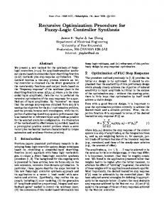
The block diagram of the complete drive system is shown in Fig. 1. The system consists of PV array, threephase inverter, and three-phase squirrel cage induction motor with associated control technique. The indirect vector control technique, assisted by minimal rule based FLC is proposed which ensures good performance of the drive. The mechanical model of the induction motor drive system may be written in generalized form as:
Te J
d r B r Tl dt
(1)
As the load are having nonlinear mechanical characteristics. The load can be modeled as
Manuscript received December 21, 2012; revised April 18, 2013. Bhavnesh Kumar and Yogesh K Chauhan are with school of engineering, Gautam Buddha University, 201310, India (
[email protected];
[email protected]) Vivek Shrivastava is in Electrical Engineering Department, NIT Delhi (
[email protected])
©2013 Engineering and Technology Publishing doi: 10.12720/joace.1.4.296-300
SYSTEM DESCRIPTION & CONTROL
Tl Kr Lr M 2
296
(2)
Journal of Automation and Control Engineering Vol. 1, No. 4, December 2013
where K, L, and M are arbitrary constants. By combining eq. (1) and (2)
combination of number of series and/or parallel connected solar cells. In literature several models of PV array are available which differ among themselves through the procedure and the number of parameters involved in the calculation of voltage and current. For this work a PV array is modeled based on the solar cell which are usually represented by a dc equivalent circuit given in Fig. 2 [8]. The PV array has a non-linear output varying with level of solar insolation and temperature, therefore, the maximum power of PV at each time will be based on their conditions. So, the effects of the changes in temperature and solar irradiation levels are also included in the final PV array model. The mathematical relation between current- voltages of the PV array is given by Eq. 7 [9].
d r 2 ( B L) r K r C (3) dt Small incremental change Te in electromagnetic torque Te results in a corresponding change r in motor speed r . Then, (3) can be rewritten as Te J
d r ( B L) r K ( r ) 2 (4) dt
Te J
Three phase Inverter
PV Array
Induction motor
VPV
AkTC I ph I r I c ln q Ir
I c Rs
(7)
VPV and I C are output current and voltage of the cell respectively, Rs is cell resistance, I ph is Where
Reference speed
Fuzzy logic Speed Controller
Figure 1.
Vector control
photocurrent, I r is reverse saturation current of diode,
q
is electron charge, k is Boltzmann constant, and Tr is reference operating temperature of cell. The typical power-voltage (P-V) and current-voltage (I-V) characteristics of PV array are shown in Fig. 3 (a), (b).
Solar powered adjustable speed drive
Eq. (4) in its discrete form can be rewritten as Power (watt)
J e(n) ( B L) r (n) K ( r (n)) 2 (5) Ts
Te (n) Hence
Te (n)
T (n) f (e(n), (n)) e
r
(6) Voltage (volts)
discrete
(a) Power- voltage (P-V) Curve
Where e(n) change in speed error is, r (n) is
Ts is the sampling time interval, r is the actual speed and f denotes nonlinear function. III.
Current (ampere)
the change in speed,
SYSTEM COMPONENTS MODELING
A. PV Array Modeling IC
Rs
Voltage(volt)
(b) Current-voltage (I-V) Characteristic
Ir
Figure 3. Typical characteristics of PV array
VPV
I ph
B. Vector Controlled Induction Motor Modeling Coupling effect between the flux and torque component of current in the induction motor makes its speed control sluggish and complex. The classical field oriented control or vector control technique involves the transformation of electrical variables into a frame of reference which rotates with the rotor flux vector (the d-q
Figure 2. PV array equivalent circuit
A photovoltaic cell is a device used to convert sunlight into the electrical energy. PV array is basically a ©2013 Engineering and Technology Publishing
297
Journal of Automation and Control Engineering Vol. 1, No. 4, December 2013
Rr iqre p qre sl dre 0
(8)
Rr idre p dre sl qre 0
(9)
Where R r , iqr , i dr , qr , dr , sl , p are the rotor e
e
e
resistance, q- axes rotor current, d-axis rotor current, qaxis rotor flux linkage, d-axis rotor flux linkage slip speed and differential operator respectively. The rotor q-axis and d-axis flux linkages are given by
qre Lm iqse Lr iqre
(10)
(11)
e dr
L i L i e m ds
e
e r dr
Input
inductance, q-axis and d-axis stator currents respectively. Since rotor flux linkage is aligned with d-axis
qre 0
(13)
p qre 0
(14)
TABLE I.
From the above equations
Rr iqre sl r 0
(15)
R i p r 0
(16)
e r dr
idre
r Lr
Lm e iqs Lr
Lm e iqs Lr
RULEBASE ARRAY FOR FLC
e→ ce↓ NE
NE
ZE
PE
NE
NE
ZE
ZE
NE
ZE
PE
PE
ZE
PE
PE
The rules are in general format of “if anticedent1 and antecedent2 then consequent”. Linguistic terms used for input and output variables are described as: “ZE” is “Zero”; “NE” is “Negative”; and “PE” is “Positive”. The surface plot of the rules is shown in Fig. 5.
Therefore
iqre
output
In Fuzzification, the crisp input variables to the fuzzy controller are transformed into a normalized fuzzy set. Both of input linguistic variables of the FLC were scaled into a common discourse universe with values between [−1, 1]. As a consequence, it was possible to map all the variables simultaneously with a unique set of membership functions. The 3x3 size rule base given in Table I was designed in contrast to the standard rule base of 7x7.
e
(12)
Rule Base
Figure 4. Basic structure of FLC
Where, Lm , Lr , iqs and ids are mutual inductance, rotor
r dre
Inference Engine
Fuzzification
e
Defuzzification
and change in speed error ce(k ) e(k ) e(k 1) are the two inputs for the controller, while after the decision making electromagnetic torque is produced. Before giving to the fuzzy controller Input variables (speed error and change in speed error) are scaled using a scaling factor. Utmost care must be taken in choosing the scaling factor as it affects the stability, oscillations and damping of the system. The values of scaling factors Ke, Kce and Kcu calculated using the motor data are 0.006, 20 and 1 respectively. Basically it is made up of four components: fuzzification, rule base, inference engine, and defuzzification as shown in Fig. 4 [6]-[7]
frame). Indirect vector control is just like a direct vector control the only difference is that the unit vectors are computed by calculating the rotor flux angle using the measured speed position. From the d-q equivalent circuit of induction motor the following equations can be derived [4], [10]. The rotor equation of induction motor containing flux linkages as variables in synchronously rotating reference frame indicated by suffix „e‟ are given by
(17)
(18)
And the electromagnetic torque obtained from machine flux linkages and currents is given by:
Te
3 P Lm e e ( dr iqs ) 2 2 Lr
(19)
C. FLC Designing and Modeling
Figure 5.
In this paper fuzzy speed controller with two input and single output is designed, speed error e(k ) * r ©2013 Engineering and Technology Publishing
Surface view of rules.
In order to draw conclusions using the inputs and the information in the rule-base Mamdani type inference 298
Journal of Automation and Control Engineering Vol. 1, No. 4, December 2013
engine is used. Finally the decisions are defuzzified using „centre of gravity‟ (COG) method because of its known merits [11].
120 100
Rotor speed (rad/sec)
IV.
140
RESULTS & DISCUSSION
The vector controlled induction motor drive under investigation has been analyzed using extensive simulation in the Simulink/MATLAB environment. The specifications and parameters of the induction motor used in this study are given in appendix I. The Simulated characteristics of PV array at different insolation level are shown in Fig. 6 and Fig. 7 in the form of Power-voltage (P-V) characteristics and Current-voltage (I-V) characteristics respectively. There is a knee point for each curve in the P-V characteristics, where the output power from the array is maximum. On the right side of the knee point, the array terminal voltage is almost constant for each insolation and it behaves as a voltage source with low internal impedance. However, on the left side of the knee point the array behaves as a current source with high internal impedance. In this region the PV array operation is unstable and a small increase in current can collapse the terminal voltage.
80 60 40 20 0
0
0.2
Figure 8.
Power(Watt)
Stator current(ampere)
1500 1000 500
250 300 Voltage(volt)
350
400
450
500
1.6
1.8
2
0
-5
0
0.1
0.2
0.3
0.4
0.5 Time(sec)
0.6
0.7
0.8
0.9
1
Stator current response at no load.
In order to examine the robustness of the proposed drive system, the drive is suddenly loaded when it was operating under no load condition. The step rated load torque of 12 Nm is suddenly applied to the induction motor at time t = 0.6 sec. The speed response of the drive under the loading condition is shown in Fig. 10. It can be seen from the response that drive possesses a good load rejection capability with small steady state error. The stator current response is shown in Fig. 11 from which increase in stator current is evident which is required to compensate the load applied.
2000
200
1.4
5
-15
2500
150
1.2
-10
3000
100
1 Time (sec)
10
3500
50
0.8
Speed response for reference speed of 120 rad/sec at no load.
Figure 9.
0
0.6
15
4000
0
0.4
550
Figure 6. P-V characteristics at different insolation level
140 11
120 Rotor Speed(rad/sec)
10 9
Current(Ampere)
8 7 6 5 4
100 80 60 40 20
3 2
0
1 0
0
Figure 7.
100
200
300 Voltage(volt)
400
500
0
0.2
0.4
0.6
0.8
1 1.2 Time(sec)
1.4
1.6
1.8
2
600
Figure 10. Speed response with rated load applied at t=0.6 sec.
I-V characteristics at different insolation level. 15
The speed response of the proposed drive system during start up at no-load condition is shown in Fig. 8. The drive system is run to track the command speed of a 120 rad/sec. without any load. In Fig. 8 speed response graph shows no sign of overshoot/undershoot and settling time is 0.2 sec. Under the above said condition, the peak stator current is of the induction motor is noticed around 7 ampere. The response of the stator current under no load condition by the induction motor is shown in Fig. 9.
Stator current(ampere)
10
5
0
-5
-10
-15
1
1.1
1.2
1.3
1.4
1.5
1.6
1.7
1.8
1.9
2
Time(sec)
Figure 11. Stator current response with rated load applied at t=0.6 sec.
©2013 Engineering and Technology Publishing
299
Journal of Automation and Control Engineering Vol. 1, No. 4, December 2013
Y. Yao, P. Bustamante, and R. S. Ramshaw, “Improvement of induction motor drive systems supplied by photovoltaic arrays with frequency control,” IEEE Trans. on Energy Conversion,vo1. 9, no. 2, pp. 256- 262, June 1994. [2] J. Applebaum and M. S Sarma, “The operation of permanent magnet dc motors powered by a common source of solar cells,” IEEE Trans. on Energy Conversion, vol. EC-4, no. 4, pp. 635-641, December 1989. [3] C. L Putta Swamy, B. Singh, and B. P Singh, “Dynamic performance of permanent magnet brushless dc motor powered by a PV array for water pumping,” Journal of Solar Energy Materials and Solar Cells, Netherland, vo1. 36, no. 2, pp. 187-200, Feb. 1995. [4] P. C. Krause, O. Wasynczuk, and S. D. Sudhoff, Analysis of Electric Machinery and Drive Systems, 2nd ed., Wiley-IEEE Press, 2002. [5] V. Vongmanee, V. Monyakul, and U. Youngyuan, “Vector control of induction motor drive system supplied by photovoltaic arrays,” in Proc. IEEE International Conference on Communications, Circuits and Systems and West Sino Expositions, 2002, vol. 2, pp. 1753-1756. [6] T Yifan and X. Longya, “Fuzzy logic application for intelligent control of a variable speed drive,” IEEE Trans. on Energy Conversion, vol. 9, pp. 679– 685, 1994. [7] M. Arrofiq and N. Saad, “Control of induction motor drives using modified fuzzy logic methods,” in Proc. IEEE International Conference on Systems Man and Cybernetics, 2010, pp. 612-619. [8] I. H. Atlas and A. M. Sharaf, “A photovoltaic array simulation model for matlab-simulink GUI environment,” in Proc. International Conference on Clean Electric Power, 2007, pp. 341345. [9] M. A. Elgendy, B. Zahawi, and D. J. Atkinson,“Comparison of directly connected and constant voltage controlled Photovoltaic pumping systems,” IEEE Transactions on Sustainable Energy, vol. 1, no. 3, pp. 184-192, 2010. [10] V. Kokaew, M. Moshrefi-Torbati, and S. M Sharkh, “Simulation of a solar powered air compressor,” in Proc. 10th International Conference on Environment and Electrical Engineerng, 2011, pp. 1-4. [1]
Furthermore, to examine the drive performance for another operating condition it is run to follow the changes in the reference speed. Changes in reference speed are given as step changes and the even in the opposite direction. Fig. 12 shows the speed response of the drive with different reference speeds of 120, 60, -60 and 120 rad/sec respectively to follow. 150
Rotor Speed(rad/sec)
100
50
0
Reference speed Actual speed
-50
-100
0
0.2
0.4
0.6
0.8
1 Time(sec)
1.2
1.4
1.6
1.8
2
Figure 12. Speed response for different speed tracking.
V.
CONCLUSION
In this paper the solar powered induction motor drive has been analyzed for wide range of operations using simulated results in MATLAB/Simulink. The modelling equations of each component system have been detailed. The indirect vector control technique in conjunction with minimal rule based fuzzy logic speed controller has been proposed. The performance characteristics of the proposed drive system for set point control, trajectory tracking and load disturbance rejection are simulated and presented. The drive system has exhibit good performance for these operating conditions.
Bhavnesh Kumar has completed his B. Tech and M. Tech Degree from Bharat Institute of Technology, Meerut and Motilal Nehru National Institute of Technology, Allahabad respectively. At present he is working as a Faculty Associate in School of Engineering, Gautam Buddha University, Greater Noida and pursuing his Ph. D degree. His research interest includes electric drive system, intelligent controller design.
APPENDIX Specifications of induction machine: 3-phase, 415 V, 50 Hz, 4KW, squirrel cage type Parameters: Parameter
Value
Stator Resistance (Rs)
1.405
Ω Ω
Rotor Resistance
( Rr )
1.395
Stator Inductance
( Ls )
0.005839
H
Rotor Inductance
( Lr )
0.005839
H
Mutual Inductance ( Lm )
0.1722
H
Inertia (J ) (P ) Pole Pair
0.0131
Kg.m2
Friction Factor (F )
0.002985 Nm-sec
Yogesh K. Chauhan obtained B.Tech. (GBPU Pant Nagar), M.Tech. (IIT, Delhi) and Ph.D. (TU, Patiala) in 1997, 1998 and 2010 respectively. He worked as a faculty in EIED, TU, during February2000–January 2011 and presently working as an assistant professor in School of Engineering., GB University, Gr. Noida. His research interest includes power converters and drives, Induction Generators. Dr. Chauhan is a member Institute of Engineers (India), Institute of Electrical and Electronics Engineering (USA).
2
REFERENCES
©2013 Engineering and Technology Publishing
300