The 2nd International Conference on Power Electronics and their Applications (ICPEA 2015) Djelfa on 29-30 March 2015, Algeria
Fuzzy logic controllers and Three Dimensional Space Vector Modulation technique in the αβo axes for three-phase four-wire four-leg shunt active power filter A. Chebabhi1, M-K. Fellah1, M-F. Benkhoris2, A. Kessal3 ICEPS Laboratory. Djillali Liabes University of Sidi Bel-Abbes Algeria
[email protected],
[email protected] 2 IREENA Laboratory, University of Nantes at Saint Nazaire, France. 3 Faculty of Science and Technology, University of Bordj Bou Arreridj, Algeria 1
Keywords «Three-Phase Four-Wire Four -Leg SAPF», «zero-sequence», «Fuzzy logic control (FLC) », «robustness», «3D-SVM», «dqo», «αβo-axes».
Abstract In this paper, the fuzzy logic control (FLC) and Three Dimensional Space Vector Modulation (3DSVM) for three phase four wire four-leg shunt active power filter (SAPF) control in the αβo axes for power quality improvements under balanced and unbalanced loads are proposed. In order to, robustness, stabilized, minimized the harmonics of source currents and output voltage, reducing the magnitude of neutral current, eliminated the zero-sequence current, compensated the reactive power in the four–wire distribution network, and to exceeding of the DC voltage, switching losses, constant switching frequency of the four leg inverter. The fuzzy logic control (FLC) is used to reference currents and DC-bus voltage of the four leg inverter controls. Also, for a good dynamic, the four-leg shunt active power filter is implemented with the real, imaginary and zero-sequence instant powers (pq0) theory in the αβo-axes for generate and extract the reference currents which should be injected by the four-leg shunt active power filter and the switching signals of the four-leg inverter are generating through a Three Dimensional Space Vector Modulation (3D-SVM). Selected simulation results have been shown to validate the proposed system.
I.
INTRODUCTION
Modern industrial and domestic equipment are increasingly using more single-phase loads connected with electronic circuits having a non-linear behavior. They generated in the distribution networks of harmonic disturbances causing harmful effects. [1-3] Many teams around the world are observing, studying, trying to model the harmonics in order to better understand them and be able to suggest more effective solutions to avoid the appearance of pollution and limit their spread. One of the most widespread solutions is the shunt active power filter which is responsible for canceling the harmonic currents presented in the electrical network [4-5]. The principle of the shunt active power filter is to generate harmonic currents in phase opposition to those existing on the electrical network. The current absorbed by the pollutant single phase loads is non-sinusoidal, while the current generated by the shunt active power filter is such that the current network is nonsinusoidal. The conventional three-leg shunt active power filters for three-phase three-wire and four-wire distribution systems have already been presented. These three-leg shunt active power filters can compensate the harmonic current generated by three-phase nonlinear loads; however they are not
preferable to compensate for harmonic current due to single-phase non-linear loads connected to a four-wire distribution network and the amplitude of the zero-sequence current is not reduced [12]. To remedy it will be necessary to provide a four-leg shunt active power filter [8-10]. The mathematical model of the three-phase four-wire four-leg shunt active power filter connected to four-wire electrical network for supplying the three single phase nonlinear loads figure 1 is a multiinput multi-output nonlinear model [19]. Several strategies for decoupling the nonlinearity are proposed in the literature [24]. The PI controller used requires precise linear mathematical models [22], which are difficult to obtain, and fails to perform satisfactorily under parameter variations, nonlinearity, loads disturbance, etc [11-12]. It will cause DC voltage over shoot (going beyond) and inrush reference currents which will lead to protection or even equipment damage when SAPF is plunged into the system. The DC voltage over shoot and starting current have been the constraints which restrict the development of SAPF. For the control of reference currents, DC bus voltage and to decoupling the nonlinearity, the fuzzy logic control strategy with pq0 theory in the αβo-axes is applied. The fuzzy logic controller has been widely applied to power converters due to its operation characteristics such as fastness, robustness and stability for large loads variations [19-22]. Indeed, we find that this control strategy rapidly rejects the variation of nonlinear loads it can be concluded that the pursuit performances are little affected and remarkable robustness.
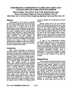
Fig. 1: Schematic block diagram of shunt active power filter with fuzzy logic control (FLC) technique. Also currently, researchers are still continuing to improve the output voltage forms of the four-leg inverter for obtain the best results, both from the point of view of a better extraction of disturbances (improving the dynamic regime, reduction THD, low switching losses and to constant switching frequency) that used a new inverter switching signals control technique for better quality waveforms. In this paper, the four-leg inverter used to eliminated the zero-sequence current, compensated harmonics and reactive power in the four–wire distribution network is controlled by the new inverter
switching signals control technique called three-dimensional Space Vector modulation (3D-SVM) technique [11], [17-19].
II. FOUR-LEG SHUNT ACTIVE POWER FILTER The four-leg shunt active power filter connected to the four wire network, as shown in figures 1-2, has four leg switches reversible current, controlled the closing and opening, realized from GTO or IGBT and an anti parallel diode. The energy storage of the DC bus voltage is done by intermediary of a capacitor of capacitance Cdc subjected to voltage Vdc. The output filter, typically first order (Rf, Lf) is used to connect the four leg inverter to the four wire network and to filter the harmonic currents high frequency. [11]
Fig. 2: Schematic of the four leg inverter A.
Mathematical model of the four leg SAPF
The differential equations describing the dynamic model of the four-leg shunt active power filter are defined in αβo-axes, as given in equation (1) [6]. di f dt di f dt di f 0 dt dVdc dt
Rf
Rf
Rf
Lf
if
1 1 vf vl Lf Lf
if
1 1 vf vl Lf Lf
if 0
1 1 vf 0 vl 0 Lf Lf
Lf Lf
(1)
Pdc* CVdc
The neutral current isn and zero sequence current are io related by the equation below: 1 1 i0 is1 is 2 is3 isn 3 3
(2)
III. THE PQ0 THEORY The real, imaginary and zero-sequence instant powers (pq0) theory has been successfully employed in a wide field of applications, and many contributions have been made in order to generalize it [19]. It has also been applied successfully in controllers of active power line conditioners [7], [18]. The real power pl, the imaginary power ql and the zero-sequence power pl0 are expressed by the following matrix: p v l l q v l l p 0 l0
v l v l 0
0 i l 0 i l v i l0 l0
(3)
Components of instantaneous real, imaginary and zero- sequence powers can be expressed as the sum of a DC component and an AC component:
p p p l l l q q q l l l p p p l0 l0 l0
When pl , ql et pl are DC components and pl , ql et pl are AC components. Equation (5), we can deduce the corresponding current components: vl 0 vl vl 0 vl 0 pl il 1 i 0 ql l v (v 2 v 2 ) vl 0 vl vl 0 vl il 0 l 0 l l 0 0 (vl2 vl2 ) pl 0
(4)
(5)
IV. FUZZY LOGIC CONTROL Fuzzy logic control technology is deduced from fuzzy set theory; it was introduced by Zadeh in 1965. In fuzzy set theory develops the transitions between membership and non-membership function. Therefore, limitation or boundaries of fuzzy sets can be undefined and ambiguous and useful for approximate systems design. In order to implement the fuzzy logic control algorithm of a four-leg shunt active power filter. [14], [22] The block diagram of a fuzzy controller (FLC) is shown in figure 3.
Fig. 3: Basic configuration of fuzzy logic controller (FLC) To apply the fuzzy logic control on the three phase four–wire four -leg shunt active filter in the αβoaxes, the system (1) should be divided into two subsystems as follows:
IV.1 Subsystem (A) ∗ ∗ ∗ In the first subsystem defined by the equation (6), the voltages 𝑣𝑓𝛼 , 𝑣𝑓𝛽 and 𝑣𝑓0 are selected as control variables, while the currents 𝑖𝑓𝛼 , 𝑖𝑓𝛽 and 𝑖𝑓0 as the output filter.
di f Rf 1 1 if vf vl dt L L L f f f di Rf 1 1 f if vf vl dt L L L f f f di R f 0 f i f 0 1 v f 0 1 vl 0 dt Lf Lf Lf
(6)
IV.2 Subsystem (B) The equation which describes this subsystem is defined by: dVdc Pdc* dt Cdc Vdc
(7)
∗ In this subsystem, the power 𝑃𝑑𝑐 are considered control variables and the voltage Vdc as an output variable.
IV.3 Synthesis controllers
IV.3.1 Control currents The reference voltages vfαβo at the input of 3D-SVM block generates by the fuzzy logic controllers (FLC) are used to control the currents ifαβo will be determined depending on the error between the reference currents and currents injected by the four leg inverter. Each of these fuzzy logic controllers has two inputs, the error of the current (εifαβo), the derivative of the error (Δεifαβo) and a single output namely the command vfαβo [22]. To transform the membership functions of the fuzzy control subsets for the digital value we use, five linguistic variables, namely NB (Negative Big), NM (Negative Medium), EZ (Zero), PM (Positive Medium) and PB (Positive Big) are assigned to the input and output variables. The membership functions of the input and output variables are shown in figure 4 [13-16], [19-22]. The fuzzy rule base with 25 rules is given in Table I. For each phase, the fuzzy controller is characterized by the following elements: [22] The trapezoidal and triangular membership functions are the most used and they are proved to be good compensator between the efficiency and ease of implementation. Implication using « min » operator. Mamdani inference mechanism based on fuzzy implication. Defuzzification using the « centroid » method.
Fig. 4: Membership functions for the input and output variables of the reference currents controller
Table I. fuzzy control rule table of the reference currents controller Δε(ifαβo)
ε(ifαβo)
NB NS EZ PS PB
NB
NS
EZ
PS
PB
NB NB NB NS EZ
NB NB NS EZ PS
NB NS EZ PS PB
NS EZ PS PB PB
EZ PS PB PB PB
IV.3.2 DC-bus voltage control The direct power Pdc at the output of fuzzy logic controller (FLC) used to control the DC bus voltage of the capacitor and for compensate the losses power of the four leg inverter, will be determined according to the error between the reference voltage and the compensating voltage. This fuzzy controller has two inputs, the error (εVdc), the derivative of this error (ΔεVdc) and a single output namely the command Pdc. To transform the membership functions of the fuzzy control subsets for the digital value we use, seven linguistic variables, namely NB (Negative Big), NM (Negative Medium), NS (Negative Small), EZ (Zero), PS (Positive Small), PM (Positive Medium) and PB (Positive Big) are assigned to the input and output variables. The membership functions of the input and output variables are shown in figure 5. The fuzzy rule base with 49 rules is given in Table II.
Fig. 5: Membership functions for the input and output variables of the DC-bus voltage control
Table II. fuzzy control rule table of the DC-bus voltage control Δε(Vdc) NB
ε(Vdc)
NB NM NS EZ PS PM PB
NM
NS
EZ
PS
PM
PB
NB NB NB NB NM NS EZ NB NB NB NM NS EZ PS NB NB NM NS EZ PS PM NB NM NS EZ PS PM PB NM NS EZ PS PM PB PB NS EZ PS PM PB PB PB EZ PS PM PB PB PB PB
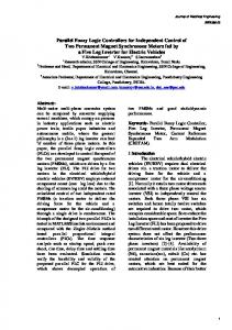
V. THREE DIMENSIONAL SPACE VECTOR MODULATION (3D-SVM) This strategy not only inherits the fixation of the switching frequency of the four leg inverter switches, but also improves the form of the output voltage and provides a good dynamic response in the four leg inverter. In 3D-SVM in the four leg inverter, there are 24=16 possible switching vectors: fourteen active vectors and two null vectors. The Vector diagram of the four leg inverter is illustrated in figure 6. [11], [16-18]:
V.1 Prism identification Six prisms in the 3D space can be identified and numbered as Prisms 1 through 6. Within the selected prism, there are six non-zero switching state vectors and two zero switching state vectors. Figure 6 shows the physical positions of the switching state vectors in αβο-axes [11], [16-17].
Fig. 6: The Vector diagram of the four leg inverter, switching vectors and the selection of the prisms
V.2 Tetrahedron Identification The tetrahedron is formed by three non-zero voltage vectors and two other zero vectors, as shown in figure 7.
Fig.7: Representation of the four tetrahedral (Te1, Te2, Te3, Te4) in the prism 1 and the three vectors of non-zero switching state in each tetrahedron The two equations for detecting the location of the first tetrahedron of the first prism is: [11] The equations of the first plane containing the switching state vectors vo(0000) v9(1000), v14(1101) is given by. avdc av dc
2 1 b.0 c vdc 3 3 1 2 1 bvdc c vdc 6 2 3
(8)
This gives; a
2 3 ,b ,c 0 2 2
(9)
The equation of the first plan is: v*f 0 v*f
2 * 3 vf 2 2
(10)
The equations of the first plane containing the switching state vectors vo(0000), v10(1001), v14(1101) is given by. avdc av dc
2 2 b.0 c vdc 3 3 1 2 1 bvdc c vdc 6 2 3
(11)
This gives; a 2, b 0, c 0
(12)
v*f 0 v*f 2
(13)
The equation of the second plan is:
Figure 8 describes the representation of tetrahedron 1 plans belonging to prism I. [18]
Fig.8: Projection of the reference vector on the adjacent vectors
V.3 Duty Cycle Calculation The principle of 3D-SVM is to project the desired reference voltage vector on three αβο-axes, as shown in figure 9. We use these projections to calculate the switching time. [11] For the tetrahedron i of the prism j, the states vectors of the four leg inverter (Vx, Vy, Vz, V1, V16) are the adjacent vectors to the reference voltage vector. These vectors are applied individually for certain periods tx, ty, tz and t0, such that the vector v * is equal to the mean value of those vectors for a period of switching: [16]
Fig.9: Projection of the reference vector on the adjacent vectors
V.4 The control pulses generation The figure 10 shows, on a switching period, the distribution of voltage vectors to be applied in the first prism tetrahedron [11], [17].
Fig. 10: Principle of generation in the pulses by 3D-SVM
VI.
SIMULATION MODEL OF A FOUR-WIRE FOUR-LEG SAPF
The performance of the proposed control strategy is evaluated through Sim Power Systems and SFunction of MATLAB. The non-linear load consists of single-phase rectifier and Series RL Branch. The components and parameters are listed in Table III.
Table III. System parameters for simulation and loads specifications Parameter Capacitance of the capacitor Cdc Coupling impedance Rf ,Lf The source voltage and frequency Source impedance Rs ,Ls Line impedance Rl ,Ll Loads impedance Rch ,Lch Unbalanced Loads R ,L
Value 5 mF 0.1 mΩ, 0.1 mH 220 V, 50Hz 1 mΩ, 1 mH 1 mΩ, 1 mH 5Ω, 10 mH 5Ω, 10 mH
VI.1 Before filtering The figure 11 shows the current waveform of the loads. It is a highly non-sinusoidal current and deformed and there is not in sync with the corresponding voltages (power factor is Pf = 0), the form of the neutral current with a maximum value of 22A in the balanced case and 70A in the unbalanced case. Figures 12, a-b shows the first phase source current's THD. Before unbalanced loads (t0.4s) it’s 10.51%.
Fig. 11: Simulation results before filtering
(a) (b) Fig.12: Magnitude Spectrum of Source Currents before filtering: (a) Before unbalanced loads, (b) After unbalanced loads
VI.2 After filtering To validate the proposed strategies in this paper, the results of numerical simulation are presented in this section. These results were obtained by applying the three phase four wire four leg SAPF with the Three Dimensional Space Vector Modulation strategy, with the conditions considered for simulation specifications are given in Table IV.
Table IV. The conditions considered for simulation PI fs =14 kHz Vdcref =800 V fc= 10 kHz fds =4Hz
Fuzzy logic control fs =14 kHz Vdcref =800 V Ke(ifα) = k e(ifβ)= 0.001, Ke(ifo)= 0.012 KΔe(ifα) = kΔe(ifβ)= 5.21*10-3, KΔe(ifo)= 1.12*10-3 Ke(Vdc)= 10-2, KΔe(Vdc)= 2.48*10-3
The simulation results of the system after compensation with the two reference currents and DC bus voltage control techniques before and after unbalanced loads are given in Figures (13-17).
(i)
(ii)
(iii)
(iv)
(v)
(vi)
Fig. 13: Simulation results using PI control; (i) three-phase source currents, (ii) three-phase loads currents,(iii) three-phase compensator and the three reference currents,(iv) source current and the corresponding voltage of phase-1,(v) neutral current,(vi) DC bus voltage.
(a) (b) Fig. 14: Spectrum of source current of phase-1 using PI control: (a) before unbalanced loads, (b) after unbalanced loads
(i)
(ii)
(iii)
(iv)
(v)
(vi)
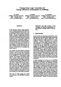
Fig. 15: Simulation results using Fuzzy logic control; (i) three-phase source currents, (ii) three-phase loads currents,(iii) three-phase compensator and the three reference harmonic currents,(iv) source current and the corresponding voltage of phase-1, (v) neutral current,(vi) DC bus voltage
(a) (b) Fig. 16: Spectrum of source current of phase-1 using fuzzy logic control: (a) before unbalanced loads, (b) after unbalanced loads Figures 13 and 15 shows the three-phase four-wire four-leg SAPF performance under unbalanced loads, the source currents waveform after filtering is sinusoidal and in phase with the corresponding voltage (the power factor is unitary) (Figs. 13-v, iv and 15-v, iv), the loads currents are non-sinusoidal and highly deformed (Figs. 13-ii and 15-ii), and the monitoring of the compensator and the reference harmonic currents if123 and if123ref is constructed with zero error for two techniques. The amplitude of the neutral current is in the range of ±5 A with PI controller and the range of ±2.3 A with fuzzy logic controller (Figs. 13-v and 15-v). The DC bus voltage presents good dynamic and static characteristics without going beyond when the fuzzy logic. When the unbalanced loads, the DC bus voltage converge to the given value with a shorttime (Figs. 15-vi). Figures 14 and16, (a-b) illustrates the harmonic spectrum of source current for the two theories, before unbalanced loads (t0.4s) its 1.94% PI control (Fig. 14, b) and 1.82% with fuzzy logic control (Fig. 16, b). The THDs of the source current with all algorithms is well below; the limit imposed by the IEEE-519 or CEI 61000 standards.
VII. CONCLUSION In this paper theoretical study with simulation of a fuzzy logic controller for a four-wire four-leg SAPF under balanced and unbalanced loads based on pq0 theory in the αβo axes to generate the reference currents which should be injected by the four-leg shunt active power filter, and to decoupling the nonlinearity of this shunt active power filter and three dimensional Space Vector Modulation (3D-SVM) to generate switching signals have shown high four-feg SAPF performances in reducing harmonics of source currents, reducing the magnitude of neutral current, eliminated the zerosequence current, compensated the reactive power in the four–wire distribution network, exceeding of the DC voltage, switching losses, constant switching frequency, and power factor correction. The Simulation results of four-wire four-leg SAPF and the spectrum of source currents THD measured verifies the reduction of harmonics, reduction of neutral current, elimination of DC voltage over shoot (going beyond) when the fuzzy logic is employed compared to conventional PI controllers. Indeed, the fuzzy logic controllers offer good static and dynamic performance resulted in a shorter response. Finally, the simulation results validated both the steady state and dynamic behavior of the proposed controllers.
Acknowledgments The authors like to thank the ICEPS laboratory for the technical support and the Algerian general direction of research for their financial support.
REFERENCES [1] Chebabhi A., Fellah M.K., Rouabah N., Khodja Dj. : Commande d’un filtre actif shunt par la technique de control directe de puissance basée sur le flux virtuel, CGE’07 EMP, ALGERIE 12-13 April,2011. [2] Matas J., García L., Miret J., Guerrero J.M, Castilla M.:Feedback Linearization of a Single-Phase Active Power Filter via Sliding Mode Control, IEEE Trans on Power Electronics 2008 vol. 23 no 1pp 116 – 125. [3] Wei L., Chunwen L., Changbo X.: Sliding mode control of a shunt hybrid active power filter based on the inverse system method, Electrical Power and Energy Systems 2014 vol. 57 pp: 39–48. [4] Chennai S., Three-level Neutral Point Clamped Shunt Active Power Filter performances using intelligent controllers RRST journal 2014 vol.59 no:3 pp: 303–313. [5] Dumitrescu A.M., Griva G., Bojoi R., Bostan V., Măgureanu R.: Current controllers design using naslin polynomial method for active power filters, RRST journal 2009 vol. 54 no 1 pp 115–124. [6] Lam C. S., Cui X-X., Wong M-C., Han Y-D.: Minimum DC-Link Voltage Design of Three-Phase FourWire Active Power Filters, IEEE, 13th Workshop on Control and Modeling for Power Electronics 10-13 June 2012, paper 101109, pp 1–5. [7] Akagi H., Watanabe E. H., and Aredes M.: Instantaneous Power Theory and Applications to Power Conditioning, IEEE, Power and Energy Magazine 2008 vol. 6 no 1 pp 80-81. [8] Abdalla I. I., Rama Rao K. S., Perumal N.: Three-phase Four-Leg Shunt Active Power Filter to Compensate Harmonics and Reactive Power, IEEE Symposium on Computers & Informatics (ISCI) 2011 paper 5958965 pp. 495 - 500. [9] Abu Hasim A. S., Talib M. H. N., Ibrahim Z.: Comparative Study of Different PWM Control Scheme for Three-Phase Three -Wire Shunt Active Power Filter, IEEE International Power Engineering and Optimization Conference (PEDCO) Melaka,Malaysia, 2012 paper 6230846 pp 119 - 123. [10] Mingxuan D., Zhihao H., Jian W., Dianguo X., Key H.: Study on Three-Leg-Based Three-Phase Four-Wire Shunt Active Power Filter, IEEE 7th International Power Electronics and Motion Control Conference ECCE Asia, 2012 vol.1 paper 6258805 pp 552 – 556. [11] Chebabhi A., Fellah M-K., Kessal A,, Benkhoris M-F.: Comparative Study of reference currents and DC bus voltage control for three phase four wire four leg SAPF to Compensate Harmonics and Reactive Power with 3D SVM, ISA Transactions, ScienceDirect, 2015. [12] Bin L., Minyong T.: Control Method of the Three-Phase Four-Leg Shunt Active” 2011 2nd International Conference on Advances in Energy Engineering Energy Procedia 14, 2012 pp. 1825 – 1830. [13] Chebabhi A., Meroufel A., Rouabah N. : Commande directe du couple d’une MAS alimentée par un onduleur de tension à trois niveaux à base de la logique floue, 2émes journées Internationales d’Electrotechnique, de maintenance et de Compatibilité Electromagnétique, CD-R, ENSET Oran-Algerie, 2010. [14] Tianhua L., Fei J.: Feedback Linearization Control of a Shunt Active Power Filter Using a Fuzzy Controller, International Journal of Advanced Robotic Systems 2013 vol.10. [15] Karuppanan P., Mahapatra K. K.: PI and fuzzy logic controllers for shunt active power filter - A report,” ISA Trans 2012 vol.51 pp163–169. [16] Kessal A., Rahmani L.: Experimental Design of a Fuzzy Controller for Improving Power Factor of Boost Rectifier", International journal of electronics, Taylor & Francis, 2012. [17] Golwala H., Chudamani R.: Comparative Study of Switching Signal Generation Techniques for Three Phase Four Wire Shunt Active Power Filter, IEEE International Electric Machines & Drives Conference (IEMDC) 15-18 May, 2011 paper 5994814 pp 1409–1414. [18] Golwala H., Chudamani R.: Simulation of three-phase four-wire shunt active power filter using novel switching technique, IEEE, International Conference on Power Electronics, Drives and Energy Systems (PEDES) & Power India, 20-23 Dec 2010 pp 1–7. [19] Saad S., Zellouma L.: Fuzzy logic controller for three-level shunt active filter compensating harmonics and reactive power, Electric Power Systems Research, 2009 vol. 79 pp1337–1341. [20] Mikkili S., Panda A. K.: RTDS hardware implementation and simulation of SHAF for mitigation of harmonics using p-q control strategy with PI and fuzzy logic controllers, Front. Electr. Electron. Eng 2012 vol. 7 no 4 pp 427–437. [21] Kabir A., Mahbub U.: Synchronous Detection and Digital control of Shunt Active Power Filter in Power Quality Improvement, IEEEPower and Energy Conference at Illinois (PECI) 2011 paper 3 pp 1-5. [22] Benaissa A., Rabhi B., Moussi A., Benkhoris M. F.: Fuzzy logic controller for three-phase four-leg fivelevel shunt active power filter under unbalanced non-linear load and distorted voltage conditions, Int J Syst Assur Eng Manag, 2013. [23] Kessal A., Rahmani L.: Power Factor Correction based on Fuzzy Logic Controller with Fixed Switching Frequency, Electronics and Electrical Engineering. - Kaunas: Technologija- Lituania 2012 vol. 118 no 2 pp 67-72. [24] Ponpandi R., Durairaj D.: A Novel Fuzzy—Adaptive Hysteresis Controller Based Three Phase Four WireFour Leg Shunt Active Filter for Harmonic and Reactive Power Compensation, Energy and Power Engineering, 2011, vol. 3 pp 422-435.