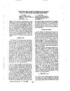
Supervisory Controller (FSC) in control of power converters. A FSC module is added to conventional narrow bandwidth voltage regulator in Power Factor.
Proceedings of the 2002 IEEE International Symposium on Intelligent Control Vancouver, Canada • October 27-30, 2002
Fuzzy Supervisory Controller for Improved Voltage Dynamics in Power Factor Corrected Converter Dwarka P. Kothari
Bhim Singh
Ashish Pandey
Centre for Energy Studies, Indian Institute of Technology, New Delhi, 110016, India
Department of Electrical Engg. Indian Institute of Technology, New Delhi, 110016, India
Centre for Energy Studies, Indian Institute of Technology, New Delhi, 110016, India email: ashish @ ieee. org
Control of PFC converters generally requires a voltage loop for DC bus voltage regulation and a current loop for actively wave-shaping the input current in shape and phase of input voltage. Presence of twice line frequency on DC link voltage in these converters and its subsequent propagation into feedback signal results in significant distortion of input current reference leading to high Total Harmonic Distortion (THD) of input current [7]. To alleviate this problem voltage loop is designed with narrow bandwidth to negate the effect of twice line frequency ripples in the feedback loop. This leads to slow voltage regulation with transients lasting for several line cycles. Few complex algorithms have been proposed for singlephase boost converter in literature with excellent result [8][10]. In these schemes twice line frequency ripple is removed from feedback path allowing bandwidth comparable to switching frequency rather than line frequency. Moreover, these schemes require additional sensing and fast processing as time period for execution of voltage control algorithm is greatly reduced at higher regulation bandwidth. Voltage source converter [11]-[12] presents similar problems in fast voltage dynamics. This converter has found application in online UPS, battery charging and traction drives where high efficiency and bidirectional power flow is required. It is therefore, an interesting exercise to evaluate fuzzy logic controller for improved voltage regulation in PFC voltage source converters, through intelligent supervision by extending the fuzzy supervision techniques, proposed by researchers and successfully commercialized by the Industry [5]-[6], to power converter control. In this work an attempt is made to improve the voltage dynamics of PFC voltage source converter with minimal complexity and no additional sensing requirement. A FSC module is cascaded with conventional low bandwidth voltage regulator with PI controller (Fig. 1) to provide artificial setpoint to the PI controller and ensure fast dynamic response. Further in this work, comprehensive mathematical modeling of the proposed FSC based VSC system is carried out and simulation results are provided showing dynamics of proposed system vis-a-vis conventional system.
Abstract- This paper investigates performance of Fuzzy Supervisory Controller (FSC) in control of power converters. A FSC module is added to conventional narrow bandwidth voltage regulator in Power Factor Corrected (PFC), Voltage Source Converter (VSC) to improve DC bus voltage regulation. PFC converter is selected for this work as conventional design of the PFC converter requires narrow bandwidth DC bus voltage regulator to negate the effect of twice line frequency in feedback path leading to slow voltage dynamics. This work demonstrates the efficacy of FSC in improving DC bus voltage regulation of VSC with conventional voltage regulator. Index Terms-Fuzzy Supervisory Controller, Voltage Source Converter, Power Factor Correction I.
INTRODUCTION
Fuzzy Logic Controllers (FLC) are increasingly finding acceptance in industry due to their proven performance in control of complex, non-linear systems where good intuitive knowledge of system behavior is present. These controllers have been proposed and commercialized in process control as well as motor and power electronics control [l]-[2] with promising results. FLCs have also shown good results in voltage regulation of PFC converters [3]-[4] essentially as setpoint regulators. These FLCs proposed in the literature have behavior similar to nonlinear PI/PID controller and offer performance enhancement over conventional controllers. However, a systematic way of embedding human knowledge and thinking required to design these controllers makes them independent of mathematical model of the system and provides a gamut of possibilities for their applications in a way not easily possible otherwise [5]. One of the several applications explored by the researchers is the use of FLC to supervise a conventionally designed PI controller for improved setpoint regulation in process [5] and motor control [6].
93
B. DC Voltage Controller
H. DESCRIPTION OF FSC BASED VOLTAGE SOURCE CONVERTER SYSTEM
PI voltage controller is selected for voltage loop for zero DC link regulation. The DC voltage v^ is sensed and compared with reference voltage vdc* obtained for FSC module. The resulting voltage error ve(n) at n"1 sampling instant is:
The principle of operation of FSC is fairly straightforward. The FSC module anticipates an impending over/undershoot and modifies the voltage reference in a way that ensures fastest possible response of PI controller. The FSC detects an overshoot or undershoot from the voltage setpoint and instantaneous output voltage feedback and accordingly manipulates the artificial setpoint of the PI controller (Fig. 1). Output of the PI controller is then multiplied to a unit template obtained from AC mains voltage to generate the current reference in shape and phase of AC voltage for PFC operation. Input current is forced to track this reference by using PWM logic, which generates switching signals for power switches.
Ve(n)=Vdc*-Vdc(n)
(3)
Output of PI voltage regulator v0(n) at n"1 sampling instant is: V0(n)= V 0(n .i)+Kp(v e ( n) -V e ( n .i,)+K t V e(n)
(4)
Where Kp and Kj are the proportional and integral gain constants. ve(n.i)is the error at the (n-l)"1 sampling instant. The output of the controller v0(n) after limiting to a safe permissible value is taken as amplitude of reference supply current ism*.
C. Fuzzy Supervisory Controller HI. MODELING AND DESCRIPTION OF CONVERTER SYSTEM
FSC module (Fig. 2) provides the artificial reference signal vdc* to PI voltage regulator. Overshoot and undershoot conditions are detected by the module from error and change in error signals. The module takes decision based on intuitively designed rule base for optimal variation of command voltage for fast transient response. (5) v dc**" Vref +
The proposed PFC converter system comprises single-phase AC supply, power converter circuit, and control scheme. In this section modeling equations of various components of the converter system are formulated separately to develop a comprehensive model for their performance simulation.
D. PWM Current Regulator
A. Supply System
Current regulation loop is required for active wave shaping of input current to achieve unity input power factor and reduced harmonics. While any current regulator can be considered we take a PWM current controller for this study.
Under normal operating conditions the supply system can be modeled as a sinusoidal voltage source of amplitude Vra and frequency fs. The instantaneous voltage is : v s (t)= Vm sin cot (1) Here t is instantaneous time. From sensed supply voltage, a unit template u(t) is estimated. u(t)=v s (t)/V m (2) Artificial Setpoinl
Setpoint
FSC
PID
Current Control and PWM Logic
Single Phase VSC
Fig. 1 Control Structure of VSC with FSC Module
Vref
Decision Making
Fig. 2. Block Diagram of FSC Module
94
Defuzzification
Output Voltage
1) Reference supply current generation The unit template u(t) obtained from sensed supply voltage is multiplied with the amplitude of reference source current Ism*. The resulting signal is reference supply current. The instantaneous value of the reference current is given as: i^Cud) (6)
similar, the FSC based system demonstrates an improved regulation. Table I. Comparison of PI and FSC controllers.
Sealing time for DC Voltage during transient
2) A ctive wave-shaping of input current The error signal (A iL = C - i J obtained by substracting sensed instantaneous input current signal from its reference is amplified and compared to fixed frequency carrier wave to generate gating signals for power devices of the converter.
Voltage Controller
Input Current THD(%)
PI FSC
0.33 0.29
Load Removal (ms)
20 10
Load Application (ms) 17 12
E. Single-phase Voltage Source Converter V. CONCLUSIONS
The converter is described by two differential equations for inductor current iL and DC link voltage across capacitor v^ (Fig. 3). P is = (v8- vp - r. iJ/Ls (7) P vdc = (ip-Vdc/RJ/Q (8) Where PWM voltage and current are vp = vdc (Sa-Sb) (9) ip = iL (Sa-Sb) (10) respectively Here Sa = 1 if switches S1 and S4 are ON, otherwise Sa = 0. Sb = 1 if switches S2 and S3 are ON, otherwise Sb = 0.
Fuzzy supervised voltage regulation of power factor corrected, voltage source converter is presented in detail. Comprehensive modeling and simulation of the converter system is carried out. Performance of the converter is evaluated on the basis of simulated results. A summery of dynamic performance is provided. While the FSC provides limited performance enhancement essentially due to narrow bandwidth design as well as requirement of low ripple at the controller output, it clearly demonstrates that FSC can find significant application in power converters where quality of signal at the controller output is not critical. The FSC module requires careful adjustments of its gain parameters, which includes gains for error and change in error signal at the input as well as gain at output of the FSC module. There also exists a tradeoff in further improving the voltage dynamics with larger gains at FSC output, which leads to chattering at the PI controller output, distorting the input current significantly. Further work includes improvement of rule base to remove chattering at high gains and also experimental verification of FSC on DSP. Investigation of other intelligent supervisory control methods is also essential for further improvement in voltage dynamics and increasing the acceptability of the proposed converter system in potential applications of VSC like online UPS and battery charging applications.
Fig. 3. Single-phase voltage source converter IV.
SIMULATION
Performance simulation of proposed converter, modeled and described, in the previous sections is carried out for lkW nominal load at 20kHz switching frequency. Values of inductor and capacitor are calculated for desired input current and output voltage ripple. A summery of performance evaluation is presented in Tables I Fig. 4 and 5 show system dynamics with conventional and FSC voltage control. FSC improved the dynamics considerably even as initial over/under shoot cannot be avoided due to narrow bandwidth design of voltage regulator. Settling time of DC bus voltage is reduced without compromising the quality of input current, indicated by THD, drawn by the converter (Table I). The FSC module changes the setpoint of the PI voltage controller leading to large changes in Input current, which is requires for fast dynamic response of DC bus voltage. Fig. 6. Shows phase trajectory of PI and FSC controllers during input voltage variations. While the trajectory is
VI. ACKNOWLEDGEMENT Third named author expresses sincere thanks to the Council of Scientific and Industrial Research for the financial assistance provided under Award No.9/86(456)/2000-EMRI to carry out this research.
95
6 380 Input Voltage
0
200 0 -200
0.1
0.2
0.3
0.4
\l UvVllVv lAlf V V V V V if V vvVV •V 11 0.1
0.2
0.3
0.5
MMV
V V V V
0.4
0.4
0.5
Time Fig. 4. Dynamic Performance of Voltage Source Converter with PI voltage regulator.
0.1
0.2
0.3 Time
0.4
Fig. 5. Dynamic Performance of Voltage Source Converter FSC.
96
0.5
6 -I 54-
il *0*-
3-
§
1-
2-
:
\PI
*
\\
• FSC
\
u 1
-2
f11
1
u
(
I
1
-3-
2
3
4,'' ~y€
6
Error
Fig. 6 Phase Plane trajectory for load variation of conventional PI and FSC controllers PWM rectifier," IEEE Trans. Power Electron., vol. 11, pp. 1-6, Jan. 1996. [10] G. Spiazzi, P. Mattavelli and L. Rossetto, "Power factor preregulators with improved dynamic response," in Proc. IEEE PESC'95, 1995, pp. 150156. [11] Y.Nishida, O. Miyashita, T.Haneyoshi, H.Tomita and A.Maeda, "A predictive instantaneous-current PWM controlled rectifier with AC-side harmonic current reduction," IEEE Trans. Ind. Electron., vol. 44, pp. 337-343, June 1997. [12] T.Shimizu, T.Fujita, G. Kimura and J.Hirose, "A unity power factor PWM rectifier with DC ripple compensation," IEEE Trans. Ind. Electron., vol. 44, pp. 447-455, Aug. 1997.
I. REFERENCES [1] B.-R. Lin, "Analysis of neural and fuzzy-power electronics control," IEE Proc. -Sci. Meas. Technol., vol.144, Jan 1997, pp. 25-33. [2] B.K. Bose, "Expert system, fuzzy logic, and neural network applications in power electronics and motion control," Proc. IEEE, vol. 82, Aug. 1994, pp. 13031323. [3] H.S.H Chung, E.P.W. Tam and S.Y.R. Hui, "Development of fuzzy logic controller for boost rectifier with active power factor correction," in Proc. IEEE PESC'99,1999, pp. 149-154. [4] P. Matavelli, S.Buso, G. Spiazzi and P. Tenti, "Fuzzy control of power factor preregulators," in Proc. Industry Applications Conference, 1995, pp. 2678 2685. [5] S. Chiu, "Using fuzzy logic in control applications: beyond fuzzy PID control," IEEE Control Systems, Oct. 1998, pp. 100-105. [6] J.-H Kim, K.-C. Kim and E.K.P. Chong, "Fuzzy precompensated PID controllers," IEEE Trans. Control. Sys. Technol., vol. 2, pp. 406-410, Nov/Dec. 1999. [7] R.W. Erickson, Fundamentals of Power Electronics. Norwell,MA: Kluwer Academic Publishers, 1999, pp. 590-624. [8] S.Wall and R. Jackson, "Fast controller design for single-phase power-factor correction systems," IEEE Trans. Ind. Electron., vol. 44, pp. 654-660, Oct. 1997. [9] M.O. Eissa, S.B. Leeb, G.C. Verghese and A.M. Stankovic, "Fast controller for a unity-power-factor
97