Volume 52, Number 4, 2011
173
STATCOM DC-Link Fuzzy Controller for Power Factor Correction Brahim FERDI, Chellali BENACHAIBA, Brahim BERBAOUI and Rachid DEHINI Abstract: power factor correction (PFC) is very important in transmission power system because as we know, Poor power factor results in reduced efficiency, which increases the cost of electricity. Static Synchronous Compensator (STATCOM) is the most important modern device used to correct the power factor by injecting reactive power. The ability of fuzzy logic to handle rough and unpredictable real world data made it suitable for a wide variety of applications, especially, when the models or processes are too complex to be analyzed by classical methods. This paper investigates the application of a fuzzy controller for controlling the DC capacitor voltage. Simulations using MATLAB/SIMULINK are carried out to verify the performance of the fuzzy controller and compare it with the conventional PI controller. The results show that the proposed controller has fast dynamic response, high accuracy of tracking the DC-voltage reference, and strong robustness to load sudden change. Keywords: STATCOM; Fuzzy Controller; Power-Factor Correction; DC-link Voltage. SRF Method
1.
INTRODUCTION
Reactive power compensation and voltage regulation are important issues in the control of electric power systems. Reactive current increases the transmission system losses, reduces the system power factor, shrink the power transmission capability and can cause large amplitude variations in the receiving end voltage. Moreover, rapid changes in the reactive power consumption of large loads can cause voltage amplitude oscillations that can lead to a change in the electric system real power demand resulting in power oscillations [1]. The rapid development of the highpower electronics industry has made Flexible AC Transmission System (FACTS) devices practical and attractive for utility applications. As one kind of the typical FACTS devices, the static synchronous compensator (STATCOM) is playing more and more important roles in reactive power provision, voltage regulation support and even in the improvement of the transient stability of power systems; because of its attractive steady state performance and operating characteristics, which have been well studied in the past years [2,3]. STATCOM is connected in parallel to the power network devices and it is based on the principle that a voltage source inverter generates a controllable AC voltage source behind a transformer-leakage reactance so that the voltage difference across the reactance produces active and reactive power exchange between the STATCOM and the transmission network[4]. Proper control strategies corresponding to the control objectives are necessary in order to achieve
efficient utilization of STATCOM. Most of the controllers used for this device are based on the PI controller [5]. Although the PI controllers are simple and easy to design, their performance deteriorates when the system operating conditions vary widely and large disturbances occur. Unlike the PI controllers, fuzzy logic controllers (FLCs) are capable of tolerating uncertainty and imprecision to a greater extent. So, they produce good results under changing operating conditions and uncertainties in system parameters [5]. During the past few decades, there are many successful applications with Fuzzy Logic Controllers (FLCs) in industry. It has been reported that they are successfully used in a number of complex and non-linear processes [6]. Moreover, the experience has shown that fuzzy controls are often a favored method of designing controllers for dynamic systems even if traditional methods can be used [7]. In this paper, a fuzzy logic controller (FLC) is proposed for controlling the STATCOM DC capacitor voltage. The STATCOM is operating in Var compensation mode to correct the power factor. Simulations using MATLAB/SIMULINK are carried out to verify the performance of the proposed controller and compare it to the Conventional proportionalintegral (PI) type regulator. The results show that the proposed controller has fast dynamic response, high accuracy of tracking the DC-voltage reference, and strong robustness to the load change. 2.
SYSTEM CONFIGURATION AND THE BASIC OPERATION
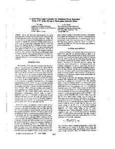
Fig. 1 shows the proposed STATCOM system configuration. In its simplest form, The STATCOM Manuscript received October 8, 2011.
© 2011 – Mediamira Science Publisher. All rights reserved.
174
ACTA ELECTROTEHNICA
reactive power supplied by the STATCOM is given by: (1) Where Q is the reactive power. Vstat is the magnitude of STATCOM output voltage. Vs is the magnitude of system voltage. x is the equivalent impedance between STATCOM and the system When Q is positive the STATCOM supplies reactive power to the system. Otherwise, the STATCOM absorbs reactive power from the system.
Fig. 1. The studied system configuration.
consists of a coupling transformer, a voltage-sourced inverter, a control system and a dc capacitor. In this arrangement, the steady-state power exchange between the device and the ac system is mainly reactive [8]. Regulating the amplitude of the STATCOM output voltage controls the reactive power exchange of the STATCOM with the ac system. If the amplitudes of the STATCOM output voltage and the ac system voltage are equal, the reactive current is zero and the STATCOM does not generate or absorb reactive power. If the amplitude of the STATCOM output voltage is increased above the amplitude of the ac system voltage, the current flows through the transformer reactance from the STATCOM to the ac system, and the device generates reactive power (capacitive). If the amplitude of the STATCOM output voltage is decreased to a level below that of the ac system, then the current flows from the ac system to the STATCOM, resulting in the device absorbing reactive power (inductive). Since the STA'I'COM is generating or absorbing only reactive power, the output voltage and the ac system voltage are in phase, when neglecting circuit losses. The current drawn from the STATCOM is 90°- shifted with respect to the ac system voltage, and it can be leading (generates reactive power) or lagging (absorbs reactive power). A capacitor is used to maintain dc voltage to the inverter. The principle of control reactive power via STATCOM is well known that the amount of type (capacitive or inductive) of reactive power exchange between the STATCOM and the system can be adjusted by controlling the magnitude of STATCOM output voltage with respect to that of system voltage. The
3.
SYNCHRONOUS REFERENCE FRAME (SRF) METHOD
Several control methods involved in generating reference signals have been discussed in literature among them being the Synchronous Reference Frame method. This method is based on the transformation of the currents in a-b-c frame to synchronously rotating dq-0 frame. Fig. 2 explains the basic building blocks of the method and its implementation in MATLAB/SIMULINK. The abc_to_dq0 Transformation block computes the direct axis, quadratic axis, and zero sequence quantities in a twoaxis rotating reference frame for a three-phase sinusoidal signal. The following transformation is used: (
(
)
(
)
(
(
)
(
)
(
( (
(2)
Where ω = rotation speed (rad/s) of the rotating frame. The reference frame is synchronized with the ac currents, and is rotating at the same frequency (ω=2πf). The angle of the transformation is detected by using a phase locked loop (PLL).To return back into a-b-c frame, the following transformation is used: ( ) ( ) (
)
(
)
(
)
(
) (3)
Out1
Vdc_ref FUZZY CONTROLLER
Vdc
[Vdc]
I_load abc
[I_Load]
dq0
dq0
sin_cos Fre q Sin_C os wt
abc_to_dq0 Transformation
))
)
Vdc_ref In1
))
abc
[I_ref]
sin_cos 0
dq0_to_abc Transformation
I_ref
Constant
Discrete Virtual PLL
Fig. 2. Block diagram of the reference current extraction and Dc-bus voltage regulation through SRF method.
175
Volume 52, Number 4, 2011
i0 is the zero sequence component which is equal to zero in 3-phase 3-wire balanced system. One of the most important characteristics of this method is that the reference currents are obtained directly from the loads currents without considering the source voltages. This is an important advantage since the generation of the reference signals is not affected by voltage unbalance or voltage distortion, therefore increasing the compensation robustness and performance.
Fig. 4. SIMULINK model of the fuzzy logic controller (FLC).
PI CONTROLLER DESIGN AND TUNING
the middle, and “S”-shaped membership function curve in the right [9]. The membership functions and the universes of the inputs are illustrated in Figure 5.
The PI controller is traditionally suitable for second and lower order systems. It can also be used for higher order plants with dominant second order behavior. The Ziegler-Nichols (Z-N) methods rely on open-loop step response or closed-loop frequency response tests, are usually used to determine the values of PI controller. In our case, the values of tuning parameters obtained are Kp=350, Ki=85. Usually, these obtained values are only initial values of PI controller and need to be adjusted repeatedly through computer simulations until the closed loop system performs or compromises are satisfied.
Fig. 5. Membership function curves of the inputs ε and ∆ε.
4.
5.
FUZZY LOGIC CONTROLLER (FLC)
The disadvantage of PI controller is its inability to react to abrupt changes in the error signal ε, because it is only capable of determining the instantaneous value of the error signal without considering the change of the rise and fall of the error, which in mathematical terms is the derivative of the error signal, denoted as ∆ε. To solve this problem, Fuzzy logic control as it is shown in Fig 3 is proposed. The determination of the output control signal, is done in an inference engine with a rule base having if-then rules in the form of IF ε is ....... AND ∆ε is ......., THEN output is ........ With the rule base, the value of the output is changed according to the value of the error signal ε, and the rateof-error ∆ε. The structure and determination of the rule base is done using trial-and-error methods and is also done through experimentation.
For the output variable, the fuzzy subsets of the membership functions have a triangular shape only as it is illustrated in Figure 6. The fuzzy control rule is illustrated in the tables I.
Fig. 6. Membership function curves of the output. Table I: FLC Rule base ε /∆ε NB NM NS Z PS PM PB
Fig. 3. Basic representation of the fuzzy logic controller (FLC).
The MATLAB/SIMULINK implementation of the fuzzy controller for one phase is shown in figure 4. All the variables’ fuzzy subsets for the inputs ε and ∆ε are defined as (NB, NM, NS, Z, PS, PM, PB). Taking into account of the coverage, sensitivity, robustness of universe, the fuzzy subsets of the membership functions use “Z”- shaped membership function in the left, triangular membership function in
6.
NB
NM
NS
Z
PS
PM
PB
PB PB PM PM PS PS Z
PB PB PM PS PS Z NS
PM PM PM PS Z NS NS
PM PM PS Z NS NM NM
PS PS Z NS NS NM NM
PS Z NS NM NM NM NB
Z NS NM NM NM NB NB
SIMULATION RESULTS AND DISCUSSION
The proposed system configuration of Figure1 has been simulated by Simulink of Matlab as it is shown in Fig.7. The task of this simulation is to evaluate the performance of the proposed fuzzy controller in steady and transient state conditions and compare the results
176
ACTA ELECTROTEHNICA
PCC A
a
Aa
A
a
A
B
B
b
Bb
B
b
B
C
C
c
Cc
C
c
C
Transformer B
C
A
A
Control [I_Load]
B
Resistive Load C
Breaker b
c
C
c
C
a
b
B
B
a
A
LOAD CURRENT
[V_DC]
A
Voltage Source
A
REF V d c
g +
C_DClink
A
a
B
b
B
C
c
C
-
VSI
A
Inductive Load
Transformer
Capacitive Load
STATCOM Fig. 7. MATLAB/SIMULINK model for the studied system configuration.
with the results given by the classical PI controller. For the sake of simplicity and clarity, only one phase is shown. Figure 8 shows line Current, active power, reactive power and power factor in load side for inductive, capacitive and resistive load. Figure 10 shows line Current, active power, reactive power and power factor in source side for inductive, capacitive and resistive load for PI and Fuzzy controller. Figure 9 shows the DC_Link voltage regulation for PI and Fuzzy controller. From these figures, we can observe: 1 - In steady state condition, it is clear that the performance of STATCOM using PI or Fuzzy controller in the compensation of reactive power is almost the same. For inductive load, a current of amplitude 0.76 pu and phase of -90.08° has been injected to compensate a reactive power of 0.5292 pu which makes the source current passes from 1.42 pu and -32° to 1.20 pu and -0.03° and the power factor from 0.8483 to 1. For capacitive load, a current of amplitude 0.76 pu and phase of 90.08° has been injected to compensate a reactive power of -0.5292 pu which makes the source current passes from 1.42 pu and 32° to 1.20 pu and 0.03° and the power factor from 0.8483 to 1. In these two cases, the regulation of the DC-Link voltage has remained unchanged and stable for
both PI and Fuzzy controller (Fig. 9). 2 - In transient state condition. The STATCOM is compensating the reactive power under sudden load changing condition. Figure 10 shows the dynamic response of the STATCOM when the load changes suddenly from inductive to capacitive then to resistive for PI and Fuzzy controller. The inductive load is switched to capacitive load at t =0.2 sec then this last is removed at t= 0.3sec to remain only a resistive load. It is clear from Figure 10 that the STATCOM succeeded in compensating the reactive power demand of the load with fast dynamics and with minimum overshoot using Fuzzy controller better than using the classical PI controller. For PI controller; the change of inductive load to capacitive load passes through a transition period (0.2 s – 0.228 s) in which the source active power oscillates between 0.908 and 0.771 pu and the source reactive power decreases to -0.122 pu also the source current increases to 1.404 pu. the change of capacitive load to resistive load passes through a transition period (0.3 s – 0.328 s) in which the source active power jumps to 1.20 pu and the source reactive power decreases to -0.127 pu also the source current increases to 2.41 pu. For Fuzzy controller; the changes of source active power, reactive power and Load side reactive power
1.5 1 0.5 0 0.1
(PU) Q 0.2 0.3 Load side Power Factor
0.4
L
0 0.1
I (PU)
P L
PF
1 0
L
0.5
L
(PU)
Load side active power 1
0.2 0.3 Time ( sec )
0.4
-1 0.1
0.2 0.3 Load side current
0.4
0.2 0.3 Time ( sec )
0.4
1 0 -1 0.1
Fig. 8. Line Current, active power, reactive power and power factor in load side.
177
Volume 52, Number 4, 2011
DC-Link Voltage (Fuzzy)
Vdc (PU)
Vdc (PU)
DC-Link Voltge (PI) 1 0.5 0
0
0.05
0.1
1 0.5 0
0.15
0
0.05
0.2
0.25 0.3 Time ( sec )
0.15
ZOOM DC-Link Voltage (Fuzzy) 1.02
Vdc (PU)
Vdc (PU)
ZOOM DC-Link Voltage (PI) 1.04 1.02 1 0.98 0.96 0.15
0.1
1 0.98 0.15
0.35
0.2
0.25 0.3 Time ( sec )
0.35
Fig. 9. DC_Link voltage regulation for sudden load change.
Source side active power (PI)
Source side active power (Fuzzy) 1.5 (PU)
(PU)
1.5
s
1
P
P
s
1 0.5 0.1
0.5 0.1 0.2 0.3 0.4 Source side reactive powe (Fuzzy) 0.5
0.2 0.3 0.4 Source side reactive power (PI) (PU)
(PU)
0.5
s
0
Q
Q
s
0
0.2 0.3 Source side current (PI)
2 1 0 -1 0.1
-0.5 0.1
0.4
s
I (PU)
s
I (PU)
-0.5 0.1
0.2
0.3
0.4
0.4
2 1 0 -1 0.1
Source side Power Factor (PI)
0.2
0.3
0.4
Souce side Power Factor (Fuzzy) s
1
1
PF
PF
s
0.2 0.3 Source side current (Fuzzy)
0.5 0.1
0.2 0.3 Time ( sec )
0.4
0.5 0.1
0.2 0.3 Time ( sec )
0.4
Fig. 10. Line Current, active power, reactive power and power factor in source side.
current are almost negligible compared to that of PI controller. Figure 9 shows the DC-Link voltage. For PI controller; in the transition period (0.2 s – 0.228 s) the DC voltage oscillates between 1.021 pu and 0.972 pu and in the transition period (0.3 s – 0.328 s) the DC voltage oscillates between 1.026 pu and 0.976 pu. But this DC voltage oscillation during transition periods for Fuzzy controller is negligible compared to that of PI controller. From the above simulations, it is clear and obvious that the proposed fuzzy controller is able to control the DC-bus voltage efficiently in steady or transient state and the performance of STATCOM using this controller in reactive power compensation is better than that of PI controller in transient state conditions. 7.
CONCLUSION
In this paper a fuzzy logic controller (FLC) for DC-Link voltage regulation of a STATCOM for Power
Factor Correction is presented. Reactive power control is the primary aim of a STATCOM, which is realized by extracting the quadrature component of load current and injecting the corresponding compensating current into the transmission line for unity power factor. The transient response of the controller is very important while compensating dynamically varying loads. Any change in the load affects the dc link voltage directly. Generally, a closed loop proportional integral controller is used to maintain the dc link voltage which has slow transient response. One of the major advantages of the proposed FLC is being less sensitive to the system parameters variation; in addition, it is characterized by a negligible response time. Simulation results analysis has shown that the proposed controller has fast dynamic response, high accuracy of tracking the DC-voltage reference, and strong robustness to load sudden variations compared to the conventional PI controller.
178
ACTA ELECTROTEHNICA
REFERENCES 1.
2.
3.
4.
5.
6.
7.
8.
M.I. Marei, E.F. El-Saadany, and M.M.A. Salama “A Novel Control Scheme for STATCOM Using Space Vector Modulation Based Hysteresis Current Controller” 11th International Conference on Harmonics and Quality of Power, 12-15 Sept. 2004 page(s): 58 – 65. Feng Liua, Shengwei Meia, Qiang Lua, Yixin Nib, Felix F. Wub, Akihiko Yokoyama, ”The nonlinear internal control of STATCOM: theory and application” Electrical Power and Energy Systems 25 (2003) 421–430. Salman Mohagheghi, Ganesh Kumar Venayagamoorthy, Ronald G. Harley, “Optimal Neuro-Fuzzy External Controller for a STATCOM in the 12-Bus Benchmark Power System” EEE TRANSACTIONS ON POWER DELIVERY, VOL. 22, NO. 4, OCTOBER 2007. Shoorangiz S.S. Farahani, Reza Hemati and Mehdi Nikzad “Comparison of Artificial Intelligence Strategies for STATCOM Supplementary Controller Design” World Applied Sciences Journal 7 (11): 1428-1438, 2009. Ahad Kazemi, Mahmoud Vakili Sohrforouzani, ”Power system damping using fuzzy controlled facts devices” Electrical Power and Energy Systems 28 (2006) 349–357. Hakkı Murat Genc, Engin Yesil, Ibrahim Eksin, Mujde Guzelkaya, Ozgur Aydın Tekin, “A rule base modification scheme in fuzzy controllers for time-delay systems” Expert Systems with Applications 36 (2009) 8476–8486. Mamdani, E.H, “Twenty years of fuzzy control: Experiences gained and lessons learnt” Proceedings of the 2nd IEEE International Conference on Fuzzy Systems (pp. 339–344). San Francisco, CA (1993). A.F. Huweg, S.M. Bashi- and N. Mariun “A STATCOM Simulation Model to Improve Voltage Sag Due to Starting of High Power Induction Motor” National Power & Energy Conference (PECon) 2004 Proceedings, Kuala Lumpur, Malaysia.
9.
S. Dib, C. Benachaiba, B. Ferdi, “Transient Performance Improvement of Dynamic Voltage Restorer by Adaptive Fuzzy PI Controller” International Review on Modelling and Simulations (I.RE.MO.S), Vol. 2, N. 2, April 2009.
Brahim FERDI Dr. Chellali BENACHAIBA Brahim BERBAOUI Rachid DEHINI Department of Electrical Engineering Bechar University B.P 417 BECHAR (08000) Algeria E-mail:
[email protected] Ferdi Brahim received the engineer degree in Electrical Engineering from INELEC Boumerdes, in 1991 and the MS degree in 2008 from Bechar University ALGERIA. Currently, He is working toward the Doctorate degree. His interests are: power quality and power system Benachaiba Chellali received the engineer degree in Electrical Engineering in 1987 from the University of Boumerdes (INH) and the M.S. degree in 1996 from Bechar University, Algeria. In 2005 he received the doctorate degree from (USTO), Algeria and currently holding the post of Assistant Professor. His current research and teaching interests are in the areas of power quality improvement, active power filters and renewable energy. Dehini Rachid received the stage license degree in electrical & engineering from the national high school of technical teachings (ENSET) ALGERIA. Currently, He is working toward the Doctorate degree. His interests are in electrical power quality and power system.