4, October 1996. Pages 363-376. Gain, frequency response, and maximum output requirements for hearing aids. John H. Macrae, PhD and Harvey Dillon, PhD.
siM , Department of Veterans Affairs Journal of Rehabilitation Research and Development Vol . 33 No . 4, October 1996 Pages 363-376
Gain, frequency response, and maximum output requirements for hearing aids John H . Macrae, PhD and Harvey Dillon, PhD National Acoustic Laboratories, Charm ood, NSW 2067 Australia
basis of the audiological characteristics of the target population . This article applies the selection procedures currently recommended by the National Acoustic Laboratories (NAL) of Australia to the audiograms of a representative group of adult and child clients of Australian Hearing Services (AHS). Gain, frequency response, and maximum output are the basic specifications for a hearing aid model or family of hearing aids . Gain refers to a measure of the overall degree of amplification and is usually quantified either by the maximum gain irrespective of frequency, by the average gain at specified frequencies, such as 0 .5, 1, and 2 kHz, or by the gain at a single reference frequency . Frequency response refers to the shape of the gain requirements across frequency, an important aspect of which is the required slope in each octave, given by the differences between required gains at adjacent octave test frequencies . Maximum output refers to the highest SPL that the hearing aid can generate and again can be quantified by the maximum irrespective of frequency, by an average across specified frequencies, or by the value at a single reference frequency . For convenience, maximum output is usually measured with a 90 dB SPL input level and will be referred to as Saturated Sound Pressure Level (SSPL). In a previous article (1) and associated report (2), hearing aid specifications were presented, which were based in part on the Byrne and Tonisson (3) gain and frequency response selection procedure then used by NAL . However, after this procedure was evaluated (4), it was revised (5) . Consequently, the hearing aid requirements were also revised, and the details were presented in an article (6) and an associated report (7).
Abstract—This article applies the gain and frequency response and maximum output selection procedures currently recommended by the National Acoustic Laboratories (NAL) of Australia to the audiograms of a representative group of adult and child clients of Australian Hearing Services (AHS) to specify the performance that is required of various types of hearing aids in order to ensure that they can provide adequate gain, frequency response, and maximum output levels for at least 90% of the AHS client population . Cumulative frequency distributions of required 2-cc coupler gain slopes were calculated for each type of aid and used to design required frequency response variations . Coupler slope requirements in different octaves were found to be independent of one another . The required range of gain-maximum output combinations was determined for each type of aid. Key words : frequency response, gain, hearing aids, maxi-
mum output.
INTRODUCTION Hearing aid designers and institutional purchasers of hearing aids have a common need to specify what performance is required of hearing aids if those hearing aids are to provide adequate gain, frequency response, and maximum output levels to a desired proportion of individuals in a target population . If hearing aids are fitted according to a prescriptive procedure, it is possible to derive such performance requirements on the This material is based on work supported by Australian Hearing Services. Address all cotTespondence and requests for reprints to John H . Macrae, PhD . =National Acoustic Laboratories . 126 Oro, Me Street . Chatswood . NSW 2067 Australia
363
364 Journal of Rehabilitation Research and Development Vol . 33 No . 4 1996
As a result of an extension of the NAL procedure to clients with severe and profound loss (8), the development of a procedure for selecting the maximum output level of hearing aids (9), and the development of new types of hearing aids, it has become necessary to carry out further updating of the requirements . For the purposes of this article, the extension of the procedure to severe and profound hearing losses will be referred to as the NAL-RP procedure . Real ear insertion gain (REIG) requirements remain the same whether they are provided by behind-the-ear (BTE), in-the-ear (ITE), in-the-canal (ITC), completely-in-the-canal (CIC), or body-level (BL) hearing aids . However, the required coupler responses differ for each of these types of hearing aid, so this article presents coupler gain and frequency response requirements separately for each type of hearing aid.
METHOD Hearing Thresholds New data were collected . These data were 700 pure-tone audiograms obtained from the case records of adult (pensioner and war veteran) clients and 400 pure-tone audiograms obtained from the case records of child clients who had been provided with hearing aids by AHS . The records were selected at random from the files of two AHS Hearing Centers . Where both ears of the client had been fitted with hearing aids, both ri g ht and left ear audiograms were included in the sample. Sensorineural, conductive, and mixed hearing losses were included in the samples . Losses were treated as sensorineural if the 3-frequency (500, 1000, and 2000 Hz) average air-bone gap was less than 15 dB . The number of audiograms with a conductive component was 105/700 (15 percent) for the adults and 64/400 (16 percent) for the children . These values are significantly less than those reported by Macrae and Dillon (6), who found 122/468 (26 percent) for adults and 80/229 (35 percent) for children . The relative frequency of each category of case in the AHS client population has also changed . Children now comprise only 6 percent of the population, whereas in 1986 they comprised 17 percent of the population . Although children are now only a very small percentage of the AHS client population, exactly the same calculations and analyses were carried out on the data for children as on the data for adults, to determine whether, in meeting the requirements of adults, the requirements of children could also be met .
For both samples, air-conduction thresholds were available at octave frequencies from 0 .25 to 8 kHz and bone-conduction thresholds were available at octave frequencies from 0 .25 to 4 kHz . In cases where the air-conduction threshold exceeded the limit of the audiometer, the threshold was assumed to be 5 dB greater than the audiometer limit . Bone-conduction thresholds that exceeded audiometric limits were assumed to be the same as the air-conduction thresholds in cases where the hearing loss was sensorineural. Bone-conduction thresholds for 8 kHz were estimated on the basis of the air-bone gaps at the frequencies up to 4 kHz . A k-means clustering algorithm devised by Hartigan (10) was used to cluster the air-conduction audiograms into 20 clusters, for both adults and children, separately. Insertion Gains Both air-conduction and bone-conduction thresholds were used in the calculation of required REIGs (RREIG) . For each audiogram, the RREIG at each octave frequency from 0 .25 to 8 kHz was calculated by means of the NAL-RP gain and frequency response selection procedure (Appendix A) . In the case of conductive and mixed hearing losses, the boneconduction thresholds were corrected for the Carhart notch and then one-quarter of the air-bone gap was added to the REIG that would have been required had the loss been purely sensorineural, as recommended by Lybarger (11) . The Hartigan k-means clustering algorithm was used to cluster the REIGs into 20 clusters, for both adults and children, separately. Coupler Gains The RREIGs were then converted into required coupler transmission gains for each type of hearing aid (BTE, ITE, ITC, CIC, and BL hearing aids) . The coupler gains are for HA 1 configuration couplers (12) in the case of ITE . ITC, and CIC aids and HA2 configuration couplers (12) in the case of BTE and BL aids . For BTE hearing aids, the HA2 coupler requirements assume that the hearing aids will be fitted with a #13 constant inner diameter (1 .93 mm) tube running from the tip of the earhook to the medial tip of the earmold . For ITE, ITC, and CIC hearing aids, audiograms with three-frequency average (3FA) thresholds (at 0 .5, 1 and 2 kHz) greater than 70 dB were deleted from the sample . The sample size for these aids was, therefore, 587 for adults and 302 for children . For BTE and BL hearing aids, response requirements were
365 MACRAE and DILLON : Response Requirements for Hearing Aids
computed separately for those with 3FA hearing losses less than (or equal to), and greater than, 70 dB HL. The conversion of REIGs to coupler transmission gains allowed for the effects of hearing aid venting in the manner described by Dillon (13) . This conversion includes the coupler response for flat insertion gain (CORFIG) values applicable to each hearing aid type, and also includes an allowance for the sound transmitted into and out from a vent and leakage around the mold . CORFIG values for BTE and ITE aids were those reported by Dillon (13) . Based on the data of FikretPasa and Revit (14), the ITC CORFIGs were derived by subtracting 3 dB at 4 kHz and 2 dB at 8 kHz from the ITE CORFIGs . CORFIGs used for CIC aids were those reported by Gudmundsen (15) . The CORFIG values used are shown in Table 1 . Reserve g ains of 15 dB (BTE and BL aids) and 10 dB (ITE, ITC, and CIC aids) were added to these CORFIG figures. To make the conversion, the optimum vent size had to be determined for each client record . The optimum vent size was calculated after estimating the maximum and minimum acceptable vent sizes . The maximum vent size was calculated from two constraints . Firstly, the maximum vent size that would avoid feedback, for each type of hearing aid, was calculated . This was derived by linearly interpolating the required insertion gain at 3 kHz and comparing it with the maximum real ear gain at 3 kHz that could be achieved for each vent size . A frequency of 3 kHz was chosen because the maximum insertion gain before feedback is less at that frequency than at other frequencies . (Because the real ear unaided response has its greatest value, on average, around 3 kHz, a greater real ear aided response is needed at 3 kHz than at other frequencies .) In the selection of the maximum vent size, a safety margin of 10 dB was allowed, to cover people
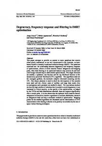
Table 1. CORFIG values used for each type of hearing aid. Aid
250
500
BTE ITE ITC CIC BL
4 1 1 -7 -2
2 2 2 -7 -5
Frequency (Hz) 1k 2k 0 —1 —1 -9 -3
1 0 0 -7 12
4k 5 -2 -5 -18 4
8k
who choose more gain than would be expected for clients with this degree of loss, and to allow for individual variation in the amount of leakage through vents and around earmolds. A second maximum vent size was determined from the required insertion gain at 250 Hz . If that gain is significant, a large vent should not be used, otherwise an excessive coupler gain will be needed because of the low-frequency gain reduction effects of vents . This maximum vent size was calculated according to Table 2 . Finally, the maximum vent size was selected to be the lesser of the two maxima described above. The minimum vent size was determined to minimize difficulties associated with the occlusion effect. The minimum vent size was calculated from the air conduction threshold at 250 Hz according to Table 3. Where two vents were equally ranked midway between the minimum and maximum vent sizes (the optimum vent size), the larger of the two vents was chosen . Optimum vent sizes were calculated for BTE, ITE, and ITC hearing aids . For CIC and body aids, an occluded (but with an average degree of leak, based on BTE earmolds) hearing aid was selected for all hearing losses. The results of the calculations for each audiogram were the maximum and the minimum values of the range of coupler gains that would provide the RREIG at each frequency . As described in Dillon (13), a tolerance of ±2 dB in achieving the RREIG (averaged across Table 2. Maximum vent size constrained by low frequency insertion gain required. Required Insertion Gain at 250 Hz (dB)
Maximum Vent Size
0 dB 0 .1 to 9 .9 dB � 10 dB
Tube (open) 1 mm Occluded
Table 3. Minimum vent size constrained by prevention of the occlusion effect.
—1
AC HTL
—11
at 250 Hz
Minimum Vent Size
30 dB HL
2 mm 1 mm Tight
-13 -23 -1 1
CORFIG = coupler response for flat insertion gain, BTE = behind the ear. ITE = in the ear . ITC = in the canal . CIC = completely in the canal, BL = body level .
AC HTL = air conduction hearing threshold level, dB = decibel, HL = hearing level .
366 Journal of Rehabilitation Research and Development Vol . 33 No . 4 1996
clients with the same audiogram), was allowed . For frequencies of 1000 Hz and above, the range of acceptable coupler gains was, consequently, about 4 dB. For audiograms requiring REIG of less than 3 dB at 250 and 500 Hz, coupler gains from negative infinity to about 20 dB (depending on the vent size) were acceptable, because the REIG provided by the aid would be determined by transmission of sound in through the vent . No single coupler gain value could be considered necessary at these frequencies for these audiograms . However, representative coupler gain values could be obtained for audiograms requiring more than 3 dB of REIG at the low frequencies . These representative values were obtained by averaging the maximum and minimum values of acceptable coupler gain . The Hartigan k-means clustering algorithm was used to cluster the required maximum and minimum coupler gains (simultaneously) into 20 clusters for each type of hearing aid, for both adults and children, separately . Cumulative probability distributions of required representative coupler gains were also calculated for each type of hearing aid, for both adults and children. Coupler Frequency Response Next, the required octave slopes (differences between the representative coupler gains at adjacent octave frequencies) and cumulative frequency distributions of the required slopes were determined for each type of hearing aid, for both adults and children . Correlations between the required slopes at adjacent octaves were also calculated to ascertain the degree to which the required slope in one octave was independent of the required slope in adjacent octaves . Maximum Output Level The required SSPL was calculated for each audiogram according to the selection procedure whose basis is described in Dillon et al . (9) . This procedure estimates the required 3FA SSPL (0 .5, 1, and 2 kHz) from the 3FA threshold values, and aims to avoid loudness discomfort and hearing aid saturation . The formula used, including an allowance for conductive hearing loss (not included in the original reference), is given in Appendix B . For CIC aids, an additional 11 dB (16) was subtracted from the formulae given in Appendix B . As discussed later in this paper, this reflects the larger real ear to coupler differences (RECD) applicable to CIC aids .
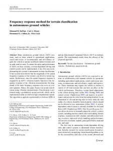
RESULTS As mentioned earlier, exactly the same calculations and analyses were carried out on the data for children as on the data for adults, to determine whether, in meeting the requirements of adults, the requirements of children could also be met . This proved largely to be the case. For this reason, the findings presented in this article are confined to adults, with the exception of the median hearing losses of the two groups. Hearing Thresholds The means of the 20 clusters of adult audiograms are given in Figure 1, along with the percentage of audiograms in each cluster. Figure 2 shows the median hearing loss for each group at each frequency. Insertion Gains The means of the 20 clusters of RREIGs for adults are given in Figure 3, along with the percentage of insertion gains in each cluster. 0
20
40
so
so
loo -o 120 0 J O (n W Ce 20 I4o
so so 100
120 250 500
1k
2k
4k
8k
250 500
1k
2k
8k
FREQUENCY (Hz)
Figure 1. The means of the 20 clusters of thresholds and the percentage of thresholds grouped into each cluster.
367 MACRAE and DILLON : Response Requirements for Hearing Aids
0
— m
20 —
q J
40
CHILDREN ADULTS
_
w 60 — ce z — Io 80 — z ore
—
to 100 —
1 250
500
I
I
!
1k 2k FREQUENCY (Hz)
4k
8k
Figure 2. Median air conduction thresholds (filled circles) and bone conduction thresholds (open squares) for the child data (left facing bars) and the adult data (right facing bars) . The bars indicate the inter-quartile range of the air conduction hearing thresholds.
70
60
50
40
30
20
40
30
20
10
0 2S0 500
lk
4k
8k
250 500
lk
2k
4k
FREQUENCY (Hz)
Figure 3. The means of the 20 clusters of the required insertion gain cu r ves and the percentage of curves grouped into each cluster .
Coupler Gains Cumulative frequency distributions of representative 2-cc coupler gains are given in Table 4 . At each frequency, the required coupler gain was excluded from the distribution if the RREIG was less than 3 dB . These low RREIG values can be satisfactorily approximated by sound traveling in through the vent/leakage paths, so the required coupler gain is unimportant, provided it is not excessive . Consequently, the number of cases is considerably less at 250 Hz and slightly less at 500 Hz, than at the higher frequencies, for all aid types except the high gain BTE and BL hearing aids, as shown in the second column of Table 4. Figures 4 and 5 show the 20 clusters for BTE and ITC coupler gains . (Similar data for BL, ITE, and CIC aids, and data for all aid types for children, are available from the authors) . The unimportance of coupler gain at 250 Hz (for approximately 50 percent of clients), and at 500 Hz (for approximately 10 percent of clients), can be seen in these figures as the widened region between the maximum and minimum acceptable coupler gains. Coupler Frequency Response Cumulative frequency distributions of required 2-cc coupler gain slopes are given in Table 5 . Again, data are only included when the RREIG is greater than, or equal to, 3 dB. The coupler frequency response variations required for each type of hearing aid are shown in Figure 6. These figures were constructed from Table 5 by including the range of slopes from the 5th to the 95th percentiles . The range of responses should thus meet the expected requirements for 90 percent of clients . (This statement assumes that the CORFIG values are correct for individual clients, as well as being appropriate when averaged across clients). Table 6 shows the product-moment correlations between the coupler gain slopes required in adjacent octaves for each type of hearing aid and the probability that each corr elation is significantly different from zero. Some of the correlations are significant at the p70 dB 113 250 29 500 113 39 113 1000 51 113 2000 52 4000 113 51 8000 113 49
29 40 51 52 53 49
32 42 54 53 56 53
34 47 56 56 61 56
42 52 61 60 65 60
49 60 69 66 71 64
59 69 78 72 77 70
69 78 85 79 84 76
75 83 89 82 86 78
79 88 93 85 88 80
82 89 98 85 91 80
BTE MED . GAIN 3FAT