Cyclone separators are gas cleaning devices that utilize the centrifugal force ... One way to pose the question of the design of a cyclone separator is: For a given ...
7 Removal of Particles from
Gas Streams
Particulate removal devices operate basically on the principle that a gas stream containing particles is passed through a region where the particles are acted on by external forces or caused to intercept obstacles, thereby separating them from the gas stream. When acted upon by external forces, the particles acquire a velocity component in a direction different from that of the gas stream. In order to design a separation device based on particulate separation by external forces, one must be able to compute the motion of a particle under such circumstances. A preliminary selection of suitable particulate emission control systems is generally based on knowledge of four items: particulate concentration in the stream to be cleaned, the size distribution of the particles to be removed, the gas flow rate, and the final allowable particulate emission rate. Once the systems that are capable of providing the required efficiencies at the given flow rates have been chosen, the ultimate selection is generally made on the basis of the total cost of construction and operation. The size of a collector, and therefore its cost, is directly proportional to the volumetric flow rate of gas that must be cleaned. The operating factors that influence the cost of a device are the pressure drop through the unit, the power required, and the quantity of liquid needed (if a wet scrubbing system). In this chapter we concentrate on the design equations that are generally used for calculating efficiencies of various types of particulate emission control equipment. We shall not consider the estimation of capital or operating costs. Devices that remove particles from gas streams rely on one or more of the following physical mechanisms: 1. Sedimentation. The particle-containing gas stream is introduced into a device or chamber where the particles settle under gravity to the floor of the chamber. Devices of this type are called settling chambers. 391
392
Removal of Particles from Gas Streams
Chap. 7
2. Migration of charged particle in an electric field. The particle-containing gas stream is introduced into a device in which the particles are charged and then subjected to an electric field. The resulting electrostatic force on the particles causes them to migrate to one of the surfaces of the device, where they are held and collected. Devices of this type are called electrostatic precipitators. 3. Inertial deposition. When a gas stream changes direction as it flows around an object in its path, suspended particles tend to keep moving in their original direction due to their inertia. Particulate collection devices based on this principle include cyclones, scrubbers, and filters. 4. Brownian diffusion. Particles suspended in a gas are always in Brownian motion. When the gas stream flows around obstacles, the natural random motion of the particles will bring them into contact with the obstacles, where they adhere and are collected. Because we know that Brownian motion is more pronounced the smaller the particle, we expect that devices based on diffusion as the separation mechanism will be most effective for small particles. The key parameter that influences the choice of which device to employ in a particular case is the particle diameter Dr As we will see, the physical mechanisms above vary greatly in their effectiveness depending on the size of the particle. Thus one of our major objectives in this chapter is to understand the effectiveness of particulate removal devices as a function of particle size. There are several different classes of particulate control equipment that we consider in this chapter. The simplest particulate control device is a settling chamber, a large chamber in which the gas velocity is slowed, allowing the particles to settle out by gravity. A cyclone operates by causing the entire gas stream to flow in a spiral pattern inside a tapered tube. Because of the centrifugal force, particles migrate outward and collect on the wall of the tube. The particles slide down the wall and fall to the bottom, where they are removed. The clean gas generally reverses its flow and exits out of the top of the cyclone. An electrostatic precipitator utilizes the electrostatic force on charged particles in an electric field to separate particles from the gas stream. A high voltage drop is established between two electrodes, and particles passing through the resulting electric field acquire charge. The charged particles migrate to and are collected on an oppositely charged plate while the clean gas flows on through the device. Periodically, the plates are cleaned by rapping to shake off the layer of dust that has accumulated. A variety of filters operate on the principle that the particulate-laden gas is forced through an assemblage of collecting elements, such as a fiber or a filter mat. As the gas passes through the assemblage, particles accumulate on the collectors. Wet collection devices called scrubbers operate on the basis of the collision of particles with droplets of water that can easily be separated from the gas because of their large size. Some general statements can be made about the nature of the various types of particulate gas-cleaning equipment. Mechanical collectors such as settling chambers or cyclones are typically much less expensive than the others but are generally only moderately efficient in particle removal. Since they are much better for large particles than for small ones, they often are used as precleaners for the more efficient final control
Sec. 7.1
393
Collection Efficiency
devices, especially at high particulate loadings. Electrostatic precipitators can treat large
volumetric flow rates of gas at relatively low pressure drops
with very high removal
efficiencies. However, electrostatic precipitators are expensive and are relatively inflexible to changes in process operating conditions. Fabric filters tend to have very high efficiencies but are expensive and are generally limited to dry, low-temperature conditions. Scrubbing can also achieve high efficiencies and offers the auxiliary advantage that gaseous pollutants can be removed simultaneously with particles. However, scrubbers can be expensive to operate, owing to their high pressure drop and to the fact that they produce a wet sludge that must be treated or disposed of. We begin the chapter with a discussion of how the collection or removal efficiency of a device may be defined.
7.1 COLLECTION EFFICIENCY We define the collection efficiency 1](Dp ) of a device for particles of diameter Dp as
1](D) p
=
1 -
number of particles of diameter D p per m3 of gas out number of particles of diameter D p per m3 of gas in
(7.1)
The overall efficiency of the device based on particle number is 1]=1-
number of particles per m 3 of gas out number of particles per m 3 of gas in
(72)
.
These efficiencies can be expressed in terms of the particle size distribution functions at the inlet and outlet sides of the device,
1](Dp )
nin(Dp ) dDp
nin(Dp ) dDp
= and
1]
nout(Dp ) dDp
-
= ---------
1
i: i:
nout(Dp )
(7.3 )
nin(Dp )
[nin(Dp )
i:
-
nout(Dp )] dDp
nin(Dp ) dDp
1] (D p ) nin(Dp ) dDp
~: nin(D
p )
(7.4 )
dDp
Removal of Particles from Gas Streams
394
Chap. 7
The definition of overall efficiency above is based on particle number. We can also define overall efficiencies based on other particle properties, such as surface area and volume (or mass). For example, the collection efficiency based on particle mass YJIII is defined as mass of particles of diameter D p per m3 of gas out mass of particles of diameter D p per m3 of gas in
(7.5)
and the overall efficiency is
~: [( 7f /6) ppD;,nin(Dp) YJIII
r
=
r
(7f /6) ppD;;nout(Dp)] dD p
(7f /6) ppD;,nin(Dp) dDp
YJ(Dp)
r
D~nin(Dp) dDp
D~nin(Dp) dDp
(7.6 )
The overall collection efficiency by mass is usually the easiest to measure experimentally. The inlet and outlet streams may be sampled by a collection device, such as a filter, that collects virtually all of the particles. A term that is sometimes used to express collection efficiency is the penetration. The penetration is based on the amount emitted rather than captured; penetration based on particle mass is just Pili = I - YJm' Alternatively, the penetration can be defined on the basis of particle number, P = I - YJ. We have called the relationship between collection efficiency and particle size simply the collection efficiency. Other terms that are used for this quantity are the grade efficiency or the fractional efficiency. An important point on the collection efficiency curve is the size for which YJ = 0.5. The particle size at this point is called the ellt size or the Cllt diameter.
7.2 SETTLING CHAMBERS Gravitational settling is perhaps the most obvious means of separating particles from a flowing gas stream. A settling chamber is, in principle, simply a large box through which the effluent gas stream flows and in which particles in the stream settle to the floor by gravity. Gas velocities through a settling chamber must be kept low enough so that settling particles are not reentrained. The gas velocity is usually reduced by expanding the ducting into a chamber large enough so that sufficiently low velocities result. Although in principle settling chambers could be used to remove even the smallest paI1ides, practical limitations in the length of such chambers restrict their applicability to the removal of particles larger than about 50 f.-tm. Thus settling chambers are normally
395
Settling Chambers
Sec. 7.2
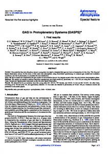
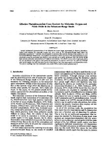
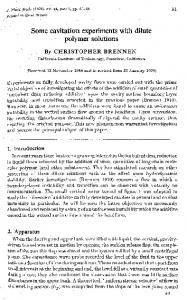
used as precleaners to remove large and possibly abrasive particles, prior to passing the of (I) simple construction and low cost, (2) small pressure drops, and (3) collection of particles without need for water. The main disadvantage of settling chambers is the large space that they require. A settling chamber is, as noted above, simply a horizontal chamber through which the particle-laden gas flows and to the floor of which the particles settle. Figure 7.1 shows a simple gravity settling chamber design. Actually, the chamber may contain a number of relatively closely spaced horizontal plates so that the distance that a paI1icle must settle to be collected is considerably smaller than the height of the overall device. In analyzing the performance of a settling chamber, the key feature is the nature of the gas flow through the device. We can distinguish three basic idealized flow situations: (I) laminar flow, (2) plug flow (velocity uniform across the cross section) with no vertical mixing of particles, (3) plug flow with complete vertical mixing of particles. Laminar flow is characterized by a parabolic-type velocity profile; such a flow would only be realized for Reynolds numbers below that for transition to turbulent flow. In a laminar flow, the time required for a particle at height y above the floor of the chamber to settle is y / V" where VI is the particle's setting velocity, and vertical mixing of particles is absent in laminar flow. (The effect of Brownian motion is generally neglected relative to the steady downward movement due to settling.) The second flow category above, plug flow with no vertical mixing of particles, is, in a sense, an approximation to laminar flow in that vertical mixing of particles is still ignored, but a flat velocity profile is assumed and the particles all settle at their settling velocities. The third category, plug flow with thorough vertical mixing, is the model for turbulent flow. In a turbulent flow settling chamber the gas velocity is assumed to be uniform across the chamber due to the turbulent mixing. Moreover, the turbulent mixing in the core of the
gas stream through other collection devices. Settling chambers offer the advantages
Gas inlet and exit ducts
Gas inlet
Dust-collecting hoppers
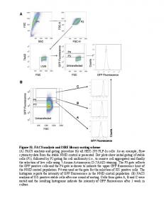
Figure 7.1 Settling chamber.
396
Removal of Particles from Gas Streams
Chap. 7
chamber overwhelms the tendency of the particles to settle and maintains a uniform particle concentration vertically across the chamber. Removal by settling can be assumed to occur in a thin layer at the bottom of the chamber. 7.2.1 Laminar Flow Settling Chamber
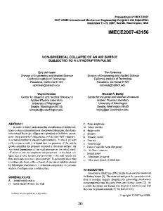
In the laminar flow settling chamber the gas velocity profile is parabolic, as shown in Figure 7.2, and as a particle below the center streamline settles, it encounters fluid moving more slowly, and thus its residence time in the chamber increases over what it would have been on the higher streamline. Conversely, particles initially above the center streamline encounter faster moving streamlines as they fall until they pass the center streamline. Consider the laminar flow settling chamber shown in Figure 7.2. The gas velocity profile for laminar flow between two parallel plates separated by a distance H with the centerline of the chamber taken as y = 0 is (7.7 ) where Ii is the mean velocity across the plates. We assume that particles are introduced uniformly across the entrance to the channel at concentration No. There will be a critical height y* such that a particle of diameter D p initially at x = 0, y = y* will be at y = - H /2 at x = L. This particle will be the "last" particle of diameter D p collected in the device. Particles of diameter D p that entered the chamber above y = y* will not be collected; clearly, the value of y* depends on the particular D p of interest. This "last" particle collected takes time tf to fall a vertical distance y* + H/2. Since VI is a constant, tf =
y*
+
H/2
(7.8 )
The vertical position of the particle at any time after entering the chamber is given by dy / dt = v y = - V" which can be integrated to give y
= y*
-
vlt
(7.9)
The horizontal position is given by dx / dt = v x ' or dx dt
=
~ Ii 2
rLI _ ~ (y* H 2
(7.10)
~~-7----2
L-------
Figure 7.2 Laminar flow settling chamber.
Sec. 7.2
397
Settling Chambers
where the local horizontal velocity of the particle is that of the gas (7.7). Integrating (7. 10) from the entrance to the exit of the chamber, we obtain (7.11 )
(7.12 ) where (3 = 2 v)3u and a = HI L. To determine the expression for the collection efficiency, we need to compute the fraction of particles of a size Dp that is collected over a length L. The flow of particles into the chamber, in number of particles per unit time, for a chamber of width W, is
The number of particles collected per unit time is that portion of the inlet flow of particles between y = -H12 and y = y*,
[v*
J-11/2
Nou,(y)WdY=NoW[v*
J-11/2
u,(y)dy
Therefore, the collection efficiency is just the ratio of the flow of particles collected to the total inlet flow,
NoW [v*
J-11/2
'I/(Dp ) = =
ur(y) dy
NouWH 1 lV' -= Hu
(7.13)
u,(y) dy
-11/2
Using (7.7), (7.13) becomes
'I/(D)
= -1
2
p
+ ~3 -y* 2 H
2 (y*)3 -
H
(7.14)
We now have two equations, (7.12) and (7.14), for the two unknowns (Y*IH) and '1/. We can simplify these further by letting z = + (y* I H). In doing so, (7.12) becomes
t
(3
-
a
=
2z
2
4
3
-
2z
-"3 z
(7.15)
Similarly, (7.14) can be expressed as
YJ(Dp )
= 3z 2
3
(7.16 )
398
Removal of Particles from Gas Streams
Chap. 7
Combining (7.15) and (7.16), we see immediately that 3{3
2et
(7.17 )
= vtL
liH
This is the equation governing the collection efficiency of a laminar flow settling chamber that consists of two parallel plates of length L separated by a distance H, with a mean gas velocity of u. To evaluate the efficiency of the laminar flow settling chamber, we need only to determine the settling velocity V t • If the particle is sufficiently small to be in the Stokes law regime, then V t = ppgD;'/18p., as derived in (5.30). Because of the large particle sizes of interest, we need not include the slip correction factor. For particles that are too large for Stokes' law to apply, the terminal settling velocity can be determined using the drag coefficient, as outlined in Section 5.3.4. Example 7.1 Efficiency of a Laminar Flow Settling Chamber in the Stokes Law Regime Consider a settling chamber for which H = 0.1 m, L = 10 m, U = 0.1 m S·l, and PI' = I g cm- 3 • At 298 K, Vair = 0.15 cm 2 S-l and p. = 1.8 X 10- 4 g cm- l S·I. Under these conditions the Reynolds number for the channel flow is 667, so laminar flow conditions exist. From (7.17) and (5.30) we find that'll = 0.03024 DJ" with D p in p.m. Thus, for these particular conditions, the collection efficiency depends on particle diameter as follows: D p (/lm)
1.0 2.0 3.0 4.0 5.0 5.75
'I (D p
)
0.03 0.12 0.27 0.48 0.76 1.0
Thus all particles with diameter exceeding 5.75 p.m are totally collected in this chamber.
7.2.2 Plug Flow Settling Chamber The second type of flow situation we consider is that of plug flow with no vertical mixing of particles. We assume that the particles are distributed uniformly across the entrance to the chamber. Whether a particle is collected is determined solely by the height y at its entrance above the collecting surface. A critical height y* can be defined such that all particles entering with y ~ y* are collected and those for which y > y* escape collection. The collection efficiency is then just
Sec. 7.2
399
Settling Chambers
which is precisely the expression (7.17) obtained for the laminar flow settling chamber. Thus, in the parabolic velocity profile case, even though the particle falls across stream-
lines with different velocities, the overall effect is as if the particle were simply falling across streamlines all having a velocity equal to the mean velocity of the flow. 7.2.3 Turbulent Flow Settling Chamber
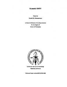
The flow in a rectangular channel can be assumed to be turbulent if the Reynolds number Re, > 4000 (McCabe and Smith, 1976, p. 52). For a duct the Reynolds number can be defined as Re c = 4 rHup I fl, where rH is the hydraulic radius, defIned as the ratio of the cross-sectional area to the perimeter. Thus, for a duct of height H and width W, rfl = HW I [2 (H + W)]. The average velocity u is just the volumetric flow rate Q divided by the cross-sectional area HW. If the duct contains N horizontal plates, each space receives a volumetric flow of Q IN and has a height HI N(neglecting the effect of plate thickness). The Reynolds number for the flow in each space is then 2Q Re = - - - - - . - C v(H + NW) The turbulent flow settling chamber is shown schematically in Figure 7.3. In the laminar flow settling chamber just considered, particles settle at all heights above the floor of the chamber, the key to the analysis being to calculate the overall residence time of the particles as they fall across streamlines. The mechanism of collection in a turbulent flow settling chamber is, although ultimately based on the settling of particles under gravity, rather different from that in the laminar flow chamber. The difference is due to the turbulent flow in the chamber. In the bulk flow in the chamber, turbulent mixing is vigorous enough so that particles are overwhelmed by the flow and do not settle. We shall assume that the turbulent mixing maintains a unifonn particle concentration over the height of the chamber. Very near the floor of the chamber a thin layer can be assumed to exist across which particles settle the short distance to the floor. Thus, once a particle, vigorously mixed in the core of the flow, enters this layer, it settles to the floor. Consider a particle close to the wall. In time dt the particle travels forward a distance dx = u dt, where u is the mean velocity of the flow in the chamber. (Thus, we assume that the mean velocity u extends into the layer in spite of the absence of turbulent mixing in the layer.) During the time interval dt the particle settles a distance dy = {II dt. Therefore, the distances dx and dy are related by dy = VI dx lu.
dy
________ --1-
_
dx
""r-..-------- L - - - - - - - - - · I
Figure 7.3 Turbulent flow settling chamber.
Removal of Particles from Gas Streams
400
Chap. 7
In order to develop an overall design equation for the turbulent flow settling chamber, let us fonn a particle balance over the vertical section dx in Figure 7.3. At the entrance to the section dx there is a unifonn distribution of particles across the entire chamber. The fraction of particles in the thin layer of thickness dy is just dy / H. Since dy was defined in tenns of dx such that dx is just the distance a particle moves in the horizontal direction while it falls the distance dy, all particles in dy are collected over the distance dx. Thus the fraction of particles collected in dx is dy / H = V t dx /u H. If the cross-sectional area of the device is A" a particle number balance over the section dx is (7.18 ) The left-hand side of (7.18) is the difference in flows in particles s -1 into and out of the volume A c dx, and the right-hand side is the number of particles s- I removed in that volume. Dividing by dx and taking the limit as dx - t 0 yields dN dx
=_
~N uH
(7.19)
If the particle number concentration at the entrance to the chamber is No, then
N(x) = No exp
ulIx)
-V (
(7.20)
Note that this equation holds for particles of each diameter since the particles are assumed not to interact with each other. Particle size dependence enters through the setThus, if desired, we can indicate the particle size dependence of N tling velocity explicitly by N (x; D p ), where N is strictly the number of particles in the diameter range (Dp , Dp + dDp ). The collection efficiency of a settling chamber of length L is
Vt.
=
1
exp
VtL) ( - liH
(7.21 )
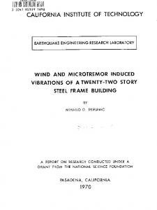
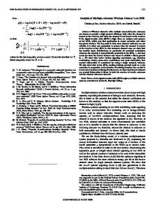
We can express the collection efficiency explicitly in tenns of particle diameter for Stokes law settling as (7.22) where Q = uHW, the volumetric flow rate of gas through the chamber, and W is the width of the chamber. We note a rather fundamental difference between the collection efficiencies for the settling chamber for laminar (and plug) and turbulent flows. The laminar flow collection
401
Settling Chambers
Sec. 7.2
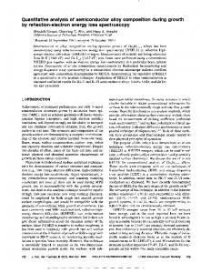
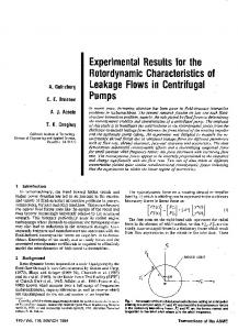
1.0.....----,---,-----,----,---y---,---,---,------,
No mixing-plug flow 0.8 Vertical mixing-plug flow
0.6
Complete mixing-plug flow
04
0.2
o
0.2
04
0.8
0.6
1.2
1.0
14
1.6
1.8
1
(~~r I
0 give (7.45 )
where the electrical migration velocity ve is evaluated at conditions at the collector surface. Equation (7.45) is to be integrated subject to N (0) = No·
Sec. 7.4
415
Electrostatic Precipitation
The migration velocity V e depends on the number of charges on the particle, which, as we will see, is a function of particle size as well as the electric field and ion density
conditions in the precipitator, and on the local electric field strength. Both q and E are in general a function of distance x down the precipitator. If it can be assumed that v" is independent of the number concentration N, integration over a unit of length L yields*
N(L) = No exp ( -
:u r dX) Ve
L
= No exp
r ) ( -Q Jo v e dx AIL
(7.46 )
where Acu = Q, the volumetric flow rate of gas through the unit, and PL = A, the collector surface area. Furthermore, if the electrical migration velocity can be assumed to be constant, then (7.46) gives N(L) = No exp (-AveIQ), and the collection efficiency is given by rJ
= 1 - exp ( -
A~e)
(7.47)
Equation (7.47) is seen to be analogous to that derived for a turbulent flow settling chamber, with only the physical mechanism leading to particle migration differing. This equation was first used in an empirical form in 1919 by Evald Anderson and derived theoretically by W. Deutsch in 1922 (White, 1984). It has generally been referred to as the Deutsch equation and sometimes as the Deutsch-Anderson equation. Although the Deutsch equation can be used to estimate the collection efficiency of an electrostatic precipitator, the assumption of constant V e is overly restrictive. In the remainder of this section, we take into account the variation in migration velocity with position in the precipitator. Our development will focus on the cylinder and wire configuration, although it can be carried through in a similar fashion for other geometries, such as parallel plates. We should point out, however, that even though it is possible to derive theoretically the electric fields and migration velocities in devices with well-defined geometry, the idealized conditions corresponding to the theory seldom exist in actual practice. Factors such as particle reentrainment and gas channeling around the collecting zones cannot be accounted for theoretically. Because of these uncertainties, industrial precipitator design is often based on empirical migration velocities for use in the Deutsch equation (White, 1984). Nevertheless, it is important to understand the underlying fundamental relationships among the variables in an electrostatic precipitator, and we will develop these relationships subsequently.
7.4.2 Generation of the Corona The mechanism for particle charging in an electrostatic precipitator is the generation of a supply of ions that attach themselves to the particles. The corona is the mechanism for *We will see subsequently that the migration velocity is, in fact, a function of the local number concentration.
416
Removal of Particles from Gas Streams
Chap. 7
fonning ions. The corona can be either positive or negative. A gas usually has a few free electrons and an equal number of positive ions, a situation that is exploited in generating a corona. When a gas is placed between two electrodes, small amount of current results as the free electrons migrate to the positive electrode and the positive ions migrate to the negative electrode. In the positive corona the discharge electrode, the wire in the cylindrical electrostatic precipitator, is at a positive potential. The few free electrons nonnally present in the gas migrate toward the wire. As the electrons approach the wire, their energy increases due to an increased attractive force. These free electrons collide with gas molecules, the collision leading in some cases to the ejection of an electron from the molecule, producing two free electrons and a positive ion. The two free electrons continue toward the positive electrode, gaining energy, until they collide with two more gas molecules, producing four free electrons and two positive ions. This process is referred to as an electron avalanche. The positive ions fonned migrate to the negative electrode. It is these positive ions that must migrate across the entire device to the negative electrode that collide with and attach to the particles in the gas. The region immediately surrounding the wire in which the electron avalanche is established is the corona. Thus, with a positive corona the particles become positively charged. The tenn "corona" arises from the fact that the electron avalanche is often accompanied by the production of light. In the negative corona the discharge electrode is maintained at a negative potential. The electron avalanche begins at the outer surface of the wire and proceeds radially outward. Close to the wire the electrons are sufficiently energetic to fonn positive ions upon collision with gas molecules, thus initiating the electron avalanche. The positive ions fonned migrate the short distance to the wire. As the electrons migrate outward into a region of lower electric field strength, they are slowed down by collisions with gas molecules. These electrons eventually have lower energy than those that are accelerated toward the positive electrode in the positive corona. These relatively low energy electrons, rather than ejecting an electron from the gas molecule upon collision, are absorbed by the gas molecules to produce negative ions. The fonnation of negative ions, which begins to occur at the outer edge of the corona, essentially absorbs all the free electrons produced in the electron avalanche at the wire surface. These negative ions then migrate to the positive electrode, in the course of which attaching to gas molecules and fonning negative ions. For a negative corona to be effective it is necessary that the gas molecules can absorb free electrons to fonn negative ions. Sulfur dioxide is one of the best electronabsorbing gases of those present in flue gases. Oxygen, CO 2 and H 2 0 are also effective electron absorbers. The negative corona is generally more stable than the positive corona, so it is preferred in most industrial applications. A by-product of the negative corona is the production of 03' which is an undesirable feature of the household use of an electrostatic precipitator with a negative corona. Moreover, since the positive corona does not need an electron-absorbing gas, it is more suitable for domestic application. A few comments are in order about the collecting, or passive, electrode. As the electrostatic precipitator is operated, a layer of the collected material builds up on the collecting electrode. Particle deposits on the precipitator collection surface must possess at least a small degree of electrical conductivity in order to conduct the ion currents from
Sec. 7.4
Electrostatic Precipitation
417
the corona to ground. The minimum conductivity required is about 10- 10 (0 cm)-I, which is the inverse of resistivity. A conductivity of 10- 10 (0 cm) -1, or a resistivity of
10 10 {1 em,
is small compared to that of ordinary metals but is much greater than that of good insulators such as silica and most plastics. The resistivity of a material is determined by establishing a current flow through a slab of known thickness of the material. As long as the resistivity of the collected dust layer is less than about 10 10 0 cm, the layer will surrender its charge to the electrode. A typical dust has a resistivity of about 8 10 0 cm at room temperature, due to a layer of water on the surface of the particles. As the temperature is increased beyond 373 K, the water is evaporated and the resistivity increases to a value characteristic of the collected solids. Fly ash resistivities can vary 8 13 from 10 to 10 0 em. When the resistivity of the layer exceeds about 10 10 0 em, the potential across the layer increases so that the voltage that can be maintained across the electrostatic precipitator decreases and the collection efficiency decreases. The electrical resistivity of collected particulate matter depends on its chemical composition, the constituents of the gas, and the temperature (Bickelhaupt, 1979; Han and Ziegler, 1984). The resistivity of fly ash is dependent on the content of S03, Na20, and to a lesser extent, hydrophilic compounds (Fe 20 3, K2, Li 20) in the ash and on the water content in the flue gas. When sulfur-containing coal is burned, from I to 5 % of the S02 is oxidized to S03 in the combustion process. The S03 condenses on the fly ash as H 2S0 4 and lowers its resistivity. Materials with very low resistivities, such as carbon black with a resistivity in the range 10- 3 0 em, are difficult to collect because these materials assume the charge of the collecting electrode upon contact and are repelled toward the discharge electrode. 7.4.3 Particle Charging
Particle charging in an electrostatic precipitator occurs in the gas space between the electrodes where the gas ions generated by the corona bombard and become attached to the particles. The gas ions may reach concentrations as high as 10 15 ions m- 3. The level of charge attained by a particle depends on the gas ion concentration, the electric field strength, the conductive properties of the particle, and the particle size. A I-J-tm particle typically acquires the order of 300 electron charges, whereas a 10-J-tm particle can attain 30,000 electron charges. Predicting the level of charge acquired by a particle is necessary in order to predict the particle's migration velocity, on the basis of which the collection efficiency can be calculated for a given set of operating conditions. There are actually two mechanisms by which particles become charged in an electrostatic precipitator. In the first mechanism particle charging occurs when ions that are migrating toward the collecting electrode encounter particles to which they become attached. In migrating between the electrodes the ions follow the electric flux lines, which are curves everywhere tangent to the electric field vector. When the particle first enters the device and is uncharged, the electric flux lines deflect toward the particle, resulting in the capture of even a larger number of ions than would be captured if the ions followed their normal path between the electrodes. As the particle becomes charged, ions begin to be repelled by the particle, reducing the rate of charging. Eventually, the particle will
Removal of Particles from Gas Streams
418
Chap. 7
acquire a saturation charge and charging will cease. This mechanism is called ion bombardment or field charging. The second mode of particle charging is diffusion charging, in which the particle acquires a charge by virtue of the random thermal motion of ions and their collision with and adherence to the particles. The theories of both field and diffusion charging, in their full generality, are quite complex and have received a great deal of attention. Strictly speaking, field and diffusion charging occur simultaneously once a particle enters an electrostatic precipitator, and hence to predict the overall charge acquired by a particle, one should consider the two mechanisms together. However, because, as we shall see, diffusion charging is predominant for particles smaller than about 1 I-tm in diameter and field charging is predominant for particles larger than about 1 I-tm, the two mechanisms often are treated in electrostatic precipitator design as if they occur independently. In doing so, one estimates the total charge on a particle as the sum of the charges resulting from each of the two separate mechanisms. 7.4.4 Field Charging
When a dielectric particle of radius Rp containing charge q is placed in a preexisting, uniform electric field E oo with an initially unipolar ion density Nioo , the electric potential at point (r, (), rp) in the region outside the sphere is (Stratton, 1941) V = -q-
41l"Eo r
+ ( -r Rp
K 1 R~) - - : 2 EooR cos () K
+2 r
P
where K is the dielectric constant of the sphere and EO is the permittivity of free space (8.85 x 10- 12 F m -I). The range of values of the dielectric constant K is K = I for a perfect insulator and K = 00 for a perfect conductor. The dielectric constants of insulating particles of mineral origin commonly are of order 2 to 10. The value of K for air is approximately 1. The first term in V is the Coulombic potential, and the second term combines the r-component external potential uniformly built by E oo and the r-component image potential resulting from the sphere dielectric polarization in EOO' The electric field around the sphere is just the negative gradient of the potential V. For the r-component of the electric field,
E = - av = _ E cos () (I ar r
00
+ 2 ~ R~) + - q -2 3 K + 2 r 41l" Eor
At the surface of the sphere
Erl
-R r-
P
=
3K q -Eoo cos () --2 + 4-R2 K
+
1l" Eo
P
Field charging occurs as the ions that are migrating in the field E oo become close to a particle (the sphere) and follow the distorted electric field lines around the particle and impinge on it. The electric field at the surface of the particle has a zero-potential
Sec. 7.4
419
Electrostatic Precipitation
circle at 0 = 00 such that for 0 ~ 00 ions will impinge on the surface and for 0 ions will drift past the particle. We find 00 by setting Er Ir~Rp = 0,
00
cos -1
=
~
00
(K-+-2 - - -q- 2 - 1 ) 3K
47rE OR p E oo
To determine the impingement rate of ions (in number per second), we need to integrate the ion flux,
where B; is the ion mobility, as given in (5.44) (minus sign for positive charging, plus sign for negative charging) from 0 = 0 to 0 = 00 and from ¢ = 0 to ¢ = 27r, lje =
~
27r ~eo
o
0
(+B;Erl ~R N;oo)R; sin 0 dO d¢ r
p
which gives (7.48 ) where q, is the saturation charge, (7.49 ) Since the rate of charging of the particle for singly charged ions equals the ion impingement rate ljC multiplied by the unit charge, ±c, we obtain for the rate of charging of the particle, dq dt
(7.50 )
o
q = q,
which can be integrated subject to q = 0 at t = 0 to give the time-dependent field charge,
q =
q,cB;N;oot cB;N;cot + 4Eo
(7.51 )
Under usual operating conditions in an electrostatic preCIpitator, the saturation charge is attained soon after the particles enter the device (White, 1984). For our purposes, then, it suffices to assume that the field-charging contribution to total particle charge is given by (7.49) qjc
= ( -3K) - 7rE oED p2 K + 2
(7.49 )
and that this charge is attained by particles immediately upon entrance into the precipitator.
Removal of Particles from Gas Streams
420
Chap. 7
We can examine the validity of this approximation from (7.51). In order for q from (7.51) to be approximated by q\, it is necessary that t » 4Eo/eBiNiOO' Now, EO is the order of 10- 11 C m -I V-I, e is the order of 10- 19 C, B i is the order of 10- 4 m2 V-I 3 S-I, and N iao is the order of 1013 m- . Thus we find that under usual conditions q ==: q\ for t > 0.1 s, and therefore approximating the field-charging contribution by (7.49) is valid for electrostatic precipitators since the residence time of the particles in the precipitator will generally exceed 1 s or so. Example 7.4 Field Charging The saturation charge on a particle attained by field charging in an electric field of strength E is given by (7.49). Charging electric fields in an electrostatic precipitator are typically in the range 300 to 600 kV m- I , but may exceed 1000 kV m- I in special cases. Let us calculate the magnitude of this charge for the following conditions: Dp = I JlIll, E = 500 kV m- I , K » 1 (conducting particle). Then from (7.49) qfc
= 4.17
X
10- 17 C
The number of electronic charges to which this charge corresponds is qfc
zp
=~ =
4.17 X 10- 17 1.60 X 10- 19
= 260 electronic charges
7.4.5 Diffusion Charging
Diffusion charging occurs as the ions in their random thermal motion collide with a particle and surrender their charge to it. In that sense the mechanism of diffusion charging is identical to that of the diffusion of uncharged vapor molecules to the surface of a particle (Section 5.5). However, because both the particle and the ions are charged, the random thermal motion of the ions in the vicinity of a particle is influenced by an electrostatic force. This force gives rise to a tendency of the ions to migrate away from the particle as the particle charge increases. The overall flux of ions to a particle thus must include both the random diffusive motion and the electrical migration. As in the case of diffusion of gas molecules to a particle, the particular flux expression depends on the ratio of the ion mean free path, Ai' to the particle radius, that is, the ion Knudsen number. We neglect the effect of the background electric field in the precipitator in analyzing the flux of ions to a particle. In the free molecule regime a kinetic theory argument can be used to deduce the rate of diffusion charging. If the particle has a charge q, the radial distribution of ions around the particle should be given by a Boltzmann expression (White, 1963) Ni,s = N i Ir=Rp = Nioo exp (
=+=
27rE::TDJ
(minus sign for positive charging; plus sign for negative charging). The rate at which ions strike the surface of the particle per unit surface area is given by the effusion flux,
Sec. 7.4
±Nj,J:j
421
Electrostatic Precipitation
Thus the rate of accumulation of charge is
1rD~
dq
_
-dt = + - - N ce exp - 4 /00
I
which can be integrated subject to q = qo at q =
+ 27rEokTDp In -
e
l ( .
exp
(_+
qe
)
27rE OkTDp
= 0 to give
t
qoe) - 27rEokTDp
+
+ Njooe2Dill ----'---_----"----C..-
8E OkT
(7.52 )
which in the case of qo = 0 becomes q = ±
27rE okTDp ( In I e
2
+ N joo e Dr,c:;!)
(7.53 )
8E OkT
where the plus sign is for positive charging and the minus sign for negative charging. In the continuum regime the flux of ions toward the particle at any distance r is given by (7.54 ) The first term of the right-hand side is the diffusive contribution to the flux and the second is that due to the field-induced migration in the vicinity of the particle. The steady-state ion concentration profile cannot be prescribed to be Boltzmann equilibrium distributed since it is now influenced by the presence of the particle. The local electric field around the particle is, since we are neglecting the overall field in the precipitator, the Coulombic field (7.55) At steady state lj is a constant independent of r. We substitute (7.55) into (7.54), and solve the differential equation subject to N j = N joo as r -> 00 to get _ljEo N = + Bjq
I
+ (±ljEO -Bjq - +N
/00
) exp (_ qe ) +--=--27rE OkTDp
(upper sign for positive charging; lower sign for negative charging). Note that if lj 0, we recover the Boltzmann distribution. To determine lj we assume that N j = 0 at r = R p , J. = /
l (
joo exp + BjqN +--
EO
qe) -27rE okTDp _ - - - 0 . -_ _
The rate of accumulation of charge is just dq dt
= BjqeNjoo r exp EO
l
(+-
qe ) _ 27rE okTDp
ll. j
I
Removal of Particles from Gas Streams
422
Chap. 7
= qo at t = 0 to give the following implicit
This equation can be integrated subject to q expression for q as a function of time:
(7.56 ) We have now developed diffusion charging results in the free molecule, (7.53), and continuum regimes, (7.56). Lassen (1961) obtained an expression that spans the two regimes,
-dq =
B;qeN;oo
dt
EO
l(
1
+ -
2qe Kn) exp (
a11'E o kTDp
+ -
qe) 211'E OkTDp
- I
j-I
(7.57)
where the ion Knudsen number Kn = 2'Aj Dr The ion mean free path is related to its molecular diffusivity by
Lassen used the value of a = 3, which we recall is used in conjunction with the FuchsSutugin interpolation formula [i.e., (5.95)]. In 1918 Enskog obtained the following expression for the binary diffusivity of spec 3 i in a background gas j,
311' (30Z
D; = 32
2
30i
+ 16z + 13) + 16z + 12 (1 + z)'Aic;
where z = m; / mj , the ratio of the mass (m;) to that of the background gas (mj ). This equation results from the second-order Chapman-Enskog solution to the Boltzmann equation for a hard sphere model. The term in the first parentheses is the correction factor to the first-order solution [recall (5.11)]. Equation (7.57) can be integrated subject to q = qo at t = 0 to give
~
m= I
(4
Kn + a
~) ~ (
m
m!
e 211'E OkTDp
)m [( ±q)'" _ (±qo)"']
=
B;eN;oot
(7.58)
EO
For Kn » I and D; = kTBje, (7.58) reduces to (7.52). Many treatments of electrostatic precipitation confine their analysis of the diffusion charging contribution to particle charge to the free molecule result (7.53). One relevant question concerns the difference in charge predicted by that equation as compared with the more complete result (7.58). We will examine that difference in Example 7.5. The classical diffusion charging equations derived above are based on the absence of an external electric field and the neglect of the electrostatic image force between the ions and the dielectric particles. Diffusion charging can be enhanced by an external electric field, so-called "field-enhanced diffusion." Results on combined field and diffusion charging have been obtained by Liu and Yeh (1968), Brock and Wu (1973), Smith and McDonald (1976), Liu and Kapadia (1978), and Withers and Melcher (1981). The
423
Electrostatic Precipitation
Sec. 7.4
effect of the electrostatic image force has been considered by Marlow and Brock (1975), Liu and Pui (1977), and Davison and Gentry (1985). In the transition regime Fuchs obtained the flux for diffusion charging by flux matching. Fuchs' formula includes the electrostatic force on the trajectory of an ion in the vicinity of a particle and has shown good agreement with recent experimental results (Adachi et al., 1985).
Example 7.5 Particle Charging by Field and Diffusion Charging Mechanisms Let us compute the charge acquired by particles as a function of D p by field and diffusion charging mechanisms separately. We consider the following conditions: T = 293 K
K
=
We need to select an ion mass. The ion masses are difficult to determine accurately, as the ions tend to form clusters that may change with time. Adachi et al. (1985) have considered the available data and have recommended:
mt
=
mi- =
Bt
=
10- 4
1.4 x
m2
V-I
109 to 130 amu 50 to 100 amu
S-I
Bi
=
Ci-
= 2.48
A-:-I
= 1.79 x 10- 8 to 1.94
D i-
= 4.80
1.9 x 10- 4 m2 V-I
S-I
Using these values, we obtain: -+ Ci
= 2.18
X
10 2 to 2.38
A+ I
= 1.44
X
10- 8 to 1.46
D+ I
= 3.54
X
10- 6 m2 S-I
X
102 m X
S-I
10- 8 m
X
X
102 to 3.52
X
102 m X
S-I
10- 8 m
1O- 6 m2 s- 1
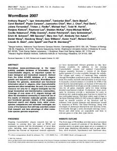
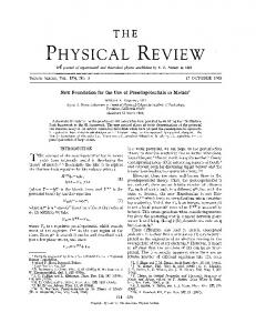
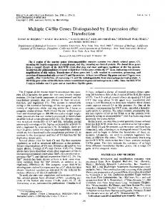
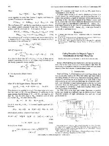
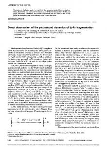
Figure 7.12 shows the number of elementary charges as a function of particle diameter for both field and diffusion charging. The field charging line is (7.49), which, since this is a log-log plot, is a straight line of slope 2. The saturation charge from field charging depends, in addition to size, only on the dielectric constant of the particle and the field strength. The diffusion charging contribution varies with time. That contribution as given by (7.58) assuming no initial charge is shown at t = 1 and 10 s. Also, we show by the dashed line the classic free molecule result (7.53). We note that the free molecule result is quite close to the more complete equation (7.58) for particle diameters less than about 1 !Lm, the regime where diffusion charging dominates. For this reason and because the field charging contribution reaches saturation very quickly, it will suffice henceforth to use (7.52) as an approximation to the diffusion charging contribution in electrostatic precipitation with qa equal to the field charge.
Example 7.6 Migration Velocity The charged particle migration velocity in an electric field was given by (7.43). Let us compute the migration velocities of the particles of Figure 7.12 at a charging time of t = I s in air at 298 K. At this temperature, the mean free path of the air molecules is Aair = 0.065 !Lm. The migration velocity is shown in Figure 7.13, and the individual contributions
424
Removal of Particles from Gas Streams
0N
Diffusion charging - - (7.58) - - - - (7.53)
1L.---l.--'o 0, ql' (0) = qFNO' The value of qj( is that given by (7.72). From (7.53) the net charge is
(7.85 )
Iii.
where time t is replaced by x The electric field strength at any position in the unit is given by (7.65) E(x,
r)
= q[,(x)
2Eo
(r _ r6) +
and that at the collector surface, assuming that r c
r
»
roEo r
(7.86 )
ro, is
(7.87) Finally, (7.79) becomes
(7.88 ) which must be solved to obtain the collection efficiency. In this section we have focused on developing the basic equations for predicting electrostatic precipitator collection efficiency. In the design of an actual electrostatic precipitator one must specify the configuration (e.g., parallel plates or wire in tube), the plate area and spacing, the corona power and current, and the pressure drop. These will depend on the gas velocity, the particle loading, the required removal efficiency, and the resistivity of the particulate matter. White (1977) presents an analysis of all of these factors in the design of an electrostatic precipitator. Example 7.7 Electrostatic Precipitator Design An airstream flowing at 1.5 m S-l at 573 K, 1 atm containing a particle mass concentration of 3 X 10- 3 g m- 3 with a particle density of 1.75 g cm- 3 is to be treated by a cylindrical electrostatie preeipitator. All particles can be assumed to have K = 3. The electrostatic precipitator is to consist of a cylinder of dimensions TO = 0.005 m and T, = 0.1 m. A value off = 0.7 can be assumed. Assume a negative corona. We want to determine the efficiency of the preciptator as a function of partiele diameter and preeipitator length.
Sec. 7.4
Electrostatic Precipitation
431
q(x) with qo q(x) = qdc
=
+
qfc
qfc
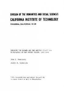
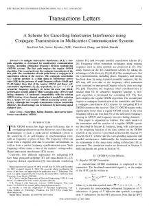
10 - 2 L----.J_L..L...L.L..LUl-_L-.L...l---l...J~ll-_L_..L_L.LLJ._l..LL_J...___L_L.L.LLJ_l..J 10- 2 10- 1 1 10' 10 2 Dp (fL m) Figure 7.15 Overall efllciency of the electrostatic precipitator in Example 7.7 as a function of particle diameter and length.
3 m .,..... _,.,,;,_.-"':1" --------_... " ,,/ 2 m .... . . - ; ' " --------- ............"
_
--.!~------_
......
q(x) with qo = qfc
q(x) = qfc only
Figure 7.16 Overall efllciency Of the electrostatic precipitator in Example 7.7 as a function of particle diameter and length. Comparison of efllciencies calculated with field and diffusion charging and field charging only.
432
Removal of Particles from Gas Streams
Chap. 7
The volumetric flow rate of air through the precipitator is Q = 0.0471 m 3 slAt 4 p = 6.126 X 10- g cm -3 and J1 = 2.85 X 10 4 I g cm- S·l. The Reynolds number is thus Re = u(2rc )p/ p. = 6448, and the flow will be turbulent. The initial number concentration of particles depends on the particle diameter. If all the entering particles are of diameter Dp , then, for a mass concentration of 3 x 10- 3 g cm - 3, the feed number concentration is
573 K the density and viscosity of air are
with D p in p.m. From (7.64) the electric field strength at the edge of the corona is Eo = - 1. 7109 x I 106 V m- . The charge/particle due to field charging at the entrance to the precipitator qt, is given by (7.72). The value of qfc depends on the size of the feed particles. For D p = 0.5 IH p.m, for example, qJc = -2.037 X 1OC. The diffusion charging contribution to the particle charge is given by (7.85). The background ion concentration will be taken as N ioo 13 3 = 10 m-- , and the ion mass mi will be estimated as in Example 7.5. Equation (7.88) can be integrated numerically subject to N = No at x = O. The efficiency at any length x is then YJ = 1 - N(x)/No' Figure 7.15 shows the overall efficiency as a function of particle diameter for precipitator lengths of 1, 2, and 3 m. In this figure we also show the efficiency calculated assuming that the particle charge is the sum of independent field and diffusion charging contributions. This assumption is seen to lead to substantial errors especially in the region of minimum efficiency. Figure 7.16 gives the same result compared to that considering field charging only. We see that for particles of diameter smaller than 1 flm, diffusion charging cannot be neglected. Figure 7.17 shows the overall efficiency as a function of precipitator length at various particle diameters.
x (m)
Figure 7.17 Overall efficiency of the electrostatic precipitator in Example 7.7 as a function of precipitator length.
Sec. 7.5
Filtration of Particles from Gas Streams
433
7.5 FILTRATION OF PARTICLES FROM GAS STREAMS
A major class of particulate air pollution control devices relies on the filtration of particles from gas streams. A variety of filter media is employed, including fibrous beds, packed beds, and fabrics. Fibrous beds used to collect airborne particles are typically quite sparsely packed, usually only about 10% of the bed volume being fibers. Packedbed filters consist of solid packing in, say, a tube and tend to have higher packing densities than do fibrous filters. Both fibrous and packed beds are widely used in ventilation systems. Fabric filters are frequently used to remove solid particles from industrial gases, whereby the dusty gas flows through fabric bags and the particles accumulate on the cloth. The physical mechanisms by which the filtration is accomplished vary depending on the mode of filtration. Conventional sparsely packed fibrous beds can be viewed as assemblages of cylinders. In such a filter the characteristic spacing between fibers is much larger than the size of the particles being collected. Thus the mechanism of collection is not simply sieving, in which the particles are trapped in the void spaces between fibers; rather, the removal of particles occurs by the transport of particles from the gas to the surface of a single collecting element. Because the filtration mechanisms in a fibrous bed can be analyzed in terms of a single collector, it is possible to describe them in considerable theoretical detail. Packed-bed filters are sometimes viewed as assemblages of interacting, but essentially separate, spherical collectors, although the close proximity of individual packing elements casts doubt as to the validity of this approach. Because of the relatively closer packing in packed-bed filters, and the resulting difficulty of describing the particle collection process in clean theoretical terms, predicting collection in such systems is more empirically based than for fibrous filters. Fabric filter efficiencies must be predicted strictly empirically since the accumulated particle layer actually does the collecting. We will devote most of our attention in this section to filtration by fibrous filters wherein theoretical predictions may be made. We begin with an analysis of the overall collection efficiency of a fibrous filter bed. Then we consider the mechanisms of collection by a single cylinder placed in a particulate-laden gas flow. Finally, we discuss briefly industrial fabric filters and packedbed fi lters . 7.5.1 Collection Efficiency of a Fibrous Filter Bed
A fibrous filter bed is viewed as a loosely packed assemblage of single cylinders. Even though the fibers are oriented in all directions in the bed, from a theoretical point of view the bed is treated as if every fiber is normal to the gas flow through the bed. Since, as we have noted, the solid fraction of the filter, ex, is generally the order of only 10%, we assume, in addition, that each fiber acts more or less independently as a collector. (As we will see later, there is assumed to be an effect of the other fibers on the flow field around an individual fiber.) Thus, to compute the particle removal by a filter bed, we basically need to determine the number of fibers per unit volume of the bed and then multiply that quantity by the efficiency of a single fiber.
Removal of Particles from Gas Streams
434
Chap. 7
1--- - - - L - - - /
/
/
/
-dx
Figure 7.18 Filter bed composed of an assemblage of single fibers.
Figure 7.18 shows a schematic of a filter bed. Let Df be the uniform diameter of each fiber comprising the bed. We will perform a balance on the number concentration of particles of diameter Dp across the bed, and, as usual, to do so we consider the balance over a slice of thickness dx. Let the cross-sectional area of the bed be An and let Lf be the total length of fiber per unit volume of the bed. Then the solid fraction of the filter can be expressed in terms of Df and Lf as (7.89 ) The gas velocity inside the filter is greater than that approaching the filter, U, due to the volume of flow excluded by the fibers. The volumetric flow rate of air through the filter is Q = Acu, so the velocity inside the bed, u oo , is related to that upstream of the bed, U, by u
=
Q ------==--- --Ac(l - ex) 1 - ex
(7.90)
The particle flows into and out of the element dx are QN Ix and QN Ix + do respectively. The number of particles removed per unit time in the element dx is the product of the flow of particles into the element and the fractional removal of particles by fibers. Let the collection efficiency of a single fiber 7J be defined as the ratio of the number of particles collected to the total number of particles in the projected upstream area (DfLf ) of the fiber. Thus the particle balance over dx is
Sec. 7.5
435
Filtration of Particles from Gas Streams
Taking the limit as dx
-+
0 and using (7.89) and (7.90), we obtain dN
(7.91 )
dx which, when integrated over a bed of length L, subject to N(O) = No, gives N(L)
Ii; =
exp
I l-
7f
4a~L (I - a) D
f
l
(7.92 )
J
The overall efficiency of the bed is
l-
N(L) I = 1 - - - = 1 - exp 'No
~I
4aYJL 7f
(1 - a) Df
J
(7.93 )
The quantity 7f (I - a) Df / 4a~ can be viewed as a characteristic depth of penetration of suspended particles in the bed. Since experiments on collection by an isolated fiber are difficult, the isolated fiber collection efficiency ~ is sometimes determined from (7.92) by measuring N(L) and No over a bed of length L and known a and Df .
7.5.2 Mechanics of Collection by a Single Fiber As we have just seen, the basis of predicting the collection efficiency of a filter bed is the collection efficiency of a single filter element in the bed. That filter element is taken as an isolated cylinder normal to the gas flow. Three distinct mechanisms can be identified whereby particles in the gas reach the surface of the cylinder:
1. Particles in a gas undergo Brownian diffusion that will bring some particles in contact with the cylinder due to their random motion as they are carried past the cylinder by the flow. A concentration gradient is established after the collection of a few particles and acts as a driving force to increase the rate of deposition over that which would occur in the absence of Brownian motion. Because the Brownian diffusivity of particles increases as particle size decreases, we expect that this removal mechanism will be most important for very small particles. When analyzing collection by Brownian diffusion, we treat the particles as diffusing massless points. 2. Interception takes place when a particle, following the streamlines of flow around a cylinder, is of a size sufficiently large that its surface and that of the cylinder come into contact. Thus, if the streamline on which the particle center lies is within a distance Dp /2 of the cylinder, interception occurs. 3. Inertial impaction occurs when a particle is unable to follow the rapidly curving streamlines around an obstacle and, because of its inertia, continues to move toward the obstacle along a path of less curvature than the flow streamlines. Thus, collision occurs because of the particle's momentum. Note that the mechanism of inertial impaction is based on the premise that the particle has mass but no size, whereas interception is based on the premise that the particle has size but no mass.
436
Removal of Particles from Gas Streams
Chap. 7
Collection may also result from electrostatic attraction when either particles or fiber or both possess a static charge. These electrostatic forces may be either direct, when both particle and fiber are charged, or induced, when only one of them is charged. Such charges are usually not present unless deliberately introduced during the manufacture of the fiber. We will not discuss the mechanisms of electrostatic attraction here. Such a discussion is presented by Strauss (1966). The size ranges in which the various mechanisms of collection are important are: Inertial impaction: > 1 J-tm Interception: > 1 J-tm Diffusion: '--l-LLLJ...l...LJ 0.001 0.01 0.1 1.0
SI Figure 7.26 Collection efficiencies by Brownian diffusion and impaction/interception for a cylinder placed transverse to the flow as a function of Stokes number for a = 0.1, Dp/Df = 0.1, and U oo = 1.0 cm s"
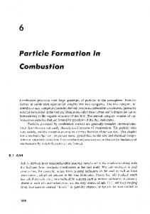
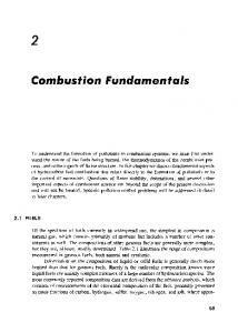
7 . 5.8 Industrial Fabric Filters Industrial fabric filtration is usually accomplished in a so-called baghouse, in which the particle-laden gases are forced through filter bags. Particles are generally removed from the bags by gravity. Figure 7.28 shows three baghouse designs, in which cleaning is accomplished by vibration [Figure 7.28(a)], air jet [Figure 7.28(b)], or traveling ring [Figure 7.28(c)]. The fabric filtration process consists of three phases. First, particles collect on individual fibers by the mechanisms we have already considered. Then an intermediate stage exists during which particles accumulate on previously collected particles, bridging the fibers. Finally, the collected particles form a cake in the form of a dust layer that acts as a packed bed filter for the incoming particles. As the dust layer accumulates, the pressure drop across the filter increases, and periodically the dust layer must be dislodged into the hopper at the bottom to "regenerate" the fabric bag. High efficiencies are attainable with fabric filters, particularly in treating combustion gases from coal-fired boil-
Sec. 7.5
Filtration of Particles from Gas Streams
453
7)diffusion
0.1
7)imp + int
0.01
0.001 L-_...LL..I.-.l-L-.L..L.LLL--....L-----l.----l.--L..l-L.J...L.J 0.01 0.1 1.0 D p (fLm)
Figure 7.27 Individual collection efficiencies due to Brownian diffusion and impaction/interception, together with total collection efficiency as a function of particle diameter. The other parameters are ex = o. I , U oo = 1.0 cm S-I, and D = 1.0/lm. f
ers. To the extent that effective operation of an electrostatic precipitator depends on the presence of S02 in the gas as an ionizable species, fabric filters can operate with no loss of efficiency with low-sulfur fuel. Fabric filters consist of semipermeable woven or felted materials that constitute a support for the particles to be removed. A brand-new woven filter cloth has fibers roughly 100 to 150 /lm in diameter with open spaces between the fibers of 50 to 75 /lm. Initially, the collection efficiency of such a cloth is low because most of the particles will pass directly through the fabric. However, deposited particles quickly accumulate, and it is the deposited particle layer that enables the high-efficiency removal once a uniform surface layer has been established. Although fiber mat filters are similar in some respects to fabric filters, they do not depend on the layer of accumulated particles for high efficiency. Fiber mat filters generally are not cleaned but are discarded. They are ordinarily used when particle concentrations are low, so that resonable service life can be achieved before discarding. Fabric filters offer the following advantages: (1) they can achieve very high collection efficiencies even for very small particles; (2) they can be used for a wide variety of particles; (3) they can operate over a wide range of volumetric flow rates; and (4) they require only moderate pressure drops. The limitations of fabric filters are: (1) operation must be carried out at temperatures lower than that at which the fabric is destroyed, or its life is shortened to an uneconomical degree; (2) gas or particle constituents
Removal of Particles from Gas Streams
454
Air jet for cleaning
Motor driven vibrator
Chap. 7
-==f:~~~~
Gas --- outlet
Gas inlet
_ _ _ Dust Dust hopper
hopper (b)
(0)
Air inlet ..
Felt filter tube
Cleaning ring travels slowly up and down
Clean air escapes through cloth
Dust retained on inside of felt "-. Air blows dust from inside of cloth (c)
Figure 7.28 Three designs for a baghouse (a) motor-driven vibrator, (b) air jet, (c) cleaning ring for removing particles from fabric filters.
that attack the fabric or prevent proper cleaning, such as sticky particles difficult to dislodge, are to be avoided; and (3) baghouses require large floor areas. The advantages of fabric filter baghouses clearly outweigh their limitations, as they currently represent close to 50% of the industrial gas-cleaning market. In a fabric filter the particle layer performs the removal task. As the layer of collected particles grows in thickness, the pressure drop across the particle layer and the underlying fabric increases. The two major considerations in the design of a fabric filter assembly are the collection efficiency and the pressure drop as a function of time of operation (since the last cleaning). Dennis and Klemm (1979) (see also Turner and McKenna, 1984) developed a series of equations for predicting outlet concentration through a fabric filter. The collection efficiency depends on the local gas velocity and the particle loading on the fabric. Empirical correlations for the pressure drop through a
Sec. 7.5
455
Filtration of Particles from Gas Streams
combined fabric-dust layer are available in Turner and McKenna (1984) and Cooper and Alley (1986). 7.5.9 Filtration of Particles by Granular Beds
An alternative to filtration in fibrous beds is the use of granular beds. The granular bed can be a fixed (packed), fluidized, or moving assemblage of inert particles. In the analysis of a granular bed filter, the bed is usually assumed to consist of an array of spherical elements through which the particle-laden gas flows. As before, the essential component of determining overall collection efficiency is the efficiency for particle capture by a single filter element, in this case a sphere. And, as before, collection occurs by the mechanisms of inertial impaction, interception, and diffusion. Gravity may also be important. A comprehensive experimental study of packed-bed filtration was reported by Gebhart et al. (1973), and their data were subsequently correlated by Balasubramanian and Meisen (1975). Given the single-sphere collection efficiency YJ, the overall collection efficiency of a granular bed of length L can be derived as follows. Let D s be the uniform diameter of each sphere comprising the bed. The collection efficiency of a single sphere is defined as the ratio of the number of particles collected per unit time to that in the projected upstream area, 7rD~ 14, of the sphere. As in the case of the fibrous bed, the interstitial gas velocity in the bed, u cx" is greater than that approaching the filter, U, due to the volume of the flow excluded by the spheres. The volumetric flow rate of air through the filter is Q = uA n so, as before, Q = uooA c( 1 a), so U oo = ul( 1 - a). If the number of spheres per unit volume of the bed is N" the solid fraction a of the bed is a = (7r 16) D; N,. We now perform the customary balance on the number concentration of particles over a differential element of bed depth dx. The flows into and out of the element dx are QN Ix and QN Ix + dx, respectively. The number of particles removed per unit time in the element dx is the product of the flow rate of particles into the element and the fraction that is removed,
Thus the balance over dx is
AcU(Nl x - Nlx+dx)
(~D~YJN\) (uooNU (Acdx)
=
Eliminating N, in terms of a, using the relation between U and u oo , and taking the limit of dx -> 0, we obtain dN =
dx
_~
2
(_a_) l I-a
N
(7.129)
D,
to be solved subject to N(O) = No. The overall bed efficiency YJh = 1 - N(L)IN o, so 'rIh = 1 - exp
[-~
(_a_) 'riLlj
L 2 1-
a
Ds
(7.130)
Removal of Particles from Gas Streams
456
Chap. 7
A number of authors have considered the efficiency of collection of particles by spheres (Michael and Norey, 1969; Paretsky et ai., 1971; Nielsen and Hill, 1976a, b; Rajagopalan and Tien, 1976; Tardos et ai., 1976, 1978; Tardos and Pfeffer, 1980). Tardos and Pfeffer (1980) have derived an expression for the collection efficiency of a single sphere by interception and gravitational effects when Dp / Ds « 1, fJ =
(1 +
DDP)2 fJe + __fJ_R__
+ Gr St
s
(7.131 )
where the efficiency for gravitational collection, Gr St fJe = 1
(7.132)
+ Gr St
with Gr = Dsg /2u~ and St = Ppu oo CcD~/9I-tDS' and where the efficiency for interception is fJR =
~ (~)3 2
I-a
(DD, )2 p
(7.133)
Note that the collection efficiency due to gravitational effects is independent of the flow field and is therefore independent of the bed solid fraction a. The efficiency expression (7.131) has been shown by Tardos and Pfeffer (1980) to be applicable for values of the Stokes number smaller than about St = 0.05. For larger values of St, a combined inertial, interception, and gravitational efficiency must be computed using the limiting trajectory .
7.6 WET COLLECTORS
Wet collectors, or scrubbers, employ water washing to remove particles directly from a gas stream. Scrubbers may be grouped broadly into two main classes: (1) those in which an array of liquid drops (sprays) form the collecting medium, and (2) those in which wetted surfaces of various types constitute the collecting medium. The first class includes spray towers and venturi scrubbers, while the second includes plate and packed towers. In this book we concentrate on the first class of devices. Scrubbing is a very effective means of removing small particles from a gas. Removal of particles results from collisions between particles and water drops. In the humid environment of a scrubber, small, dry particles also grow in size by condensation of water and thereby become easier to remove. Reentrainment of particles is avoided since the particles become trapped in droplets or in a liquid layer. A scrubber also provides the possibility of simultaneously removing soluble gaseous pollutants. The particle-laden scrubbing liquid must be disposed of-a problem not encountered in dry methods of gas cleaning. A spray scrubber is a device in which a liquid stream is broken into drops, approximately in the range 0.1 to 1.0 mm in diameter, and introduced into the particle-
Sec. 7.6
Wet Collectors
457
laden gas stream. The array of moving drops becomes a set of targets for collection of
the particles in the gas stream, Collection efficiency is computed by considering the efficiency of a single spherical collector and then summing over the number of drops per unit volume of gas flow. The relative motion between the drops and particles is an important factor in the collection efficiency because capture occurs by impaction and direct interception. (Diffusion is also important for smaller particles.) There are two general types of spray scrubbers. The first class comprises those having a preformed spray where drops are formed by atomizer nozzles and sprayed into the gas stream. These include:
1. Countercurrent gravity tower, where drops settle vertically against the rising gas stream 2. Cross-current tower, where drops settle through a horizontal gas stream 3. Cocurrent tower, where spray is horizontal into a horizontal gas stream The second class comprises those in which the liquid is atomized by the gas stream itself. Liquid is introduced more or less in bulk into a high-velocity gas flow that shatters the liquid into drops. Devices in this class are called venturi scrubbers since the highvelocity gas flow is achieved in a venturi (a contraction). Figure 7.29 illustrates four types of wet collection equipment. The simplest type of wet collector is a spray tower into which water is introduced by means of spray nozzles [Figure 7 .29(a)]. Gas flow in a spray chamber is countercurrent to the liquid, the configuration leading to maximum efficiency. Collection efficiency can be improved over the simple spray chamber with the use of a cyclonic spray tower, as shown in Figure 7.29(b). The liquid spray is directed outward from nozzles in a central pipe. An unsprayed section above the nozzles is provided so that the liquid drops with the collected particles will have time to reach the walls of the chamber before exit of the gas. An impingement plate scrubber, as shown in Figure 7.29(c), consists of a tower containing layers of baffled plates with holes (5000 to 50,000 m -2) through which the gas must rise and over which the water must fall. Highest collection efficiencies of wet collectors are obtained in a venturi scrubber, shown in Figure 7.29(d), in which water is introduced at right angles to a high-velocity gas flow in a venturi tube, resulting in the formation of very small water droplets by the flow and high relative velocities of water and particles. The high gas velocity is responsible for the breakup of the liquid. Aside from the small droplet size and high impingement velocities, collection is enhanced through particle growth by condensation. Table 7.1 summarizes particle scrubbing devices. The collection efficiency of wet collectors can be related to the total energy loss in the equipment; the higher the scrubber power, per unit volume of gas treated, the better is the collection efficiency. Almost all the energy is introduced in the gas, and thus the energy loss can be measured by the pressure drop of gas through the unit. The major advantage of wet collectors is the wide variety of types, allowing the selection of a unit suitable to the particular removal problem. As disadvantages, highpressure drops (and therefore energy requirements) must be maintained, and the handling and disposal of large volumes of scrubbing liquid must be undertaken.
458
Removal of Particles from Gas Streams Clean
nl?(~- ~- -----n' gas out
water~U in
';"/.,,' '".' """','..' '."' '.' I', ",V,I,v,l,vl" /;,",'''VI, \ 1 1 " " 1 , , 1 11,,'/1, ,I, II,
. . Mist eliminator
~
;
Spray manifold Gas distributor plate Dirty gas in Water out - - - - - . I
In
(a)
(b)
Clean gas out
V
Dirty 7:~~~ gas -d In
Impingement --------baffle plate Water out
(e)
Water out (d)
Figure 7.29 Wet collectors: (a) spray tower; (b) cyclone spray tower; (c) impingement scrubber; (d) venturi scrubber.
Chap. 7
459
Wet Collectors
Sec. 7.6 TABLE 7.1
PARTICLE SCRUBBERS
Type
Description
Plate scrubber
A vertical tower containing one or more horizontal plates (trays). Gas enters the bottom of the tower and must pass through perforations in each plate as it flows countercurrent to the descending water stream. Platc scrubbers are usually named for the type of plates they contain (e.g .. sievc plate tower). Collection efficiency increases as the diameter of the perforations decreases. A cut diameter, that collected with 50% efficiency, of about I ",m aerodynamic diameter can be achieved with 3.2-mm-diameter holes in a sieve plate.
Packed-bed scrubber
Operates similarly to packed-bed gas absorber (see Chapter 8). Collection efficiency increases as packing size decreases. A cut diameter of 1.5 ",m aerodynamic diameter can be attained in columns packed with 2.5-cm elements. Particles are collected by liquid drops that have been atomized by spray nozzles. Horizontal and vertical gas flows are used, as well as spray introduced cocurrent, countercurrent, or cross-flow to the gas. Collection efficiency depends on droplet size, gas velocity, liquid/gas ratio, and droplet trajectories. For droplets falling at their terminal velocity, the optimum droplet diameter for fine-particle collection lies in the range 100 to 500 ",m. Gravitational settling scrubbers can achieve cut diameters of about 2.0 ",m. The liquid/gas ratio is in the range 0.001 to 0.01 m' m' 3 of gas treated.
Spray scrubber
Venturi scrubber
A moving gas stream is used to atomize liquids into droplets. High gas velocities (60 to 120 m S'I) lead to high relative velocities between gas and particles and promote collection.
Cyclone scrubber
Drops can be introduced into the gas stream of a cyclone to collect particles. The spray can be directed outward from a central manifold or inward from the collector wall.
Baffle scrubber
Changes in gas flow velocity and direction induced by solid surfaces.
Impingement-entrainment scrubber
The gas is forced to impinge on a liquid surface to reach a gas exit. Some of the liquid atomizes into drops that are entrained by the gas. The gas exit is designed so as to minimize the loss of entrained droplets.
Fluidized-bed scrubber
A zone of fluidized packing is provided where gas and liquid can mix intimately. Gas passes upward through the packing, while liquid is sprayed up from the bottom and/or flows down over the top of the fluidized layer of par' ing.
Source:
Calvert (1984).
7.6.1 Spray Chamber
We begin our analysis of spray scrubbing with the conceptually simplest of the devices, a gravity spray chamber. Water droplets are introduced at the top of an empty chamber through atomizing nozzles and fall freely at their terminal settling velocities countercurrently through the rising gas stream. The particle-containing liquid collects in a pool at the bottom and must be pumped out for treatment to remove the solids, and the cleaned liquid is usually recycled to the tower. A schematic of a spray chamber is given in Figure
460
Removal of Particles from Gas Streams
Chap. 7
7.30. We assume that all the falling drops have the same diameter D,. The volumetric flow rate of water fed to the top of the chamber is W (m 3 s -I). If every drop has diameter D s ' the number of drops per second fed to the top of the chamber and passing any point in the chamber is W/[ ( 11" /6) D ~]. The drop concentration at any point in the chamber is W/[ (11" /6) D~ A c v], where A c is the cross-sectional area of the chamber and v is the fall velocity of the drops. We assume that D s remains constant in the chamber. If a drop of diameter D s is falling in still air, its terminal velocity VI is such that the drag force is just balanced by the gravitational force on the drop. Now in the spray chamber the drop is falling at a fall velocity v relative to a fixed coordinate system in the presence of a rising gas velocity vg . Thus v is not the same as V n due to the influence of the rising gas. The new fall velocity v is still determined by the equality of the drag and gravity forces. The drag force can be expressed from (5.8) as (7.134 ) W = Water feed rate
..... X +
dx
X
1 L
I
t
G = Gas feed rate
I----)o-(t·x dx
No
= Feed
concentration of particles
+
I I
I I
I I
I I
I
I
Figure 7.30 Spray chamber.
Sec. 7.6
461
Wet Collectors
where the drag force depends on the relative velocity between the drop and the gas, v + v~. By equating this drag force to the gravity force, (7.135) we find that the sum of the new fall velocity and the rising gas velocity equals the terminal velocity in still air, v
+
v g = v,
(7.136 )
Given the drop size, we can compute (or find correlations for) v" and given the volumetric flow rate of gas through the unit, we can calculate v g . Thus we can compute the water drop fall velocity from (7.136). We now wish to derive an equation governing the overall collection efficiency of a spray tower. Let YJ be the collection efficiency of particles on an individual droplet, defined as the ratio of the cross-sectional area of the hypothetical tube of gas from which the particles are all removed to the frontal area of the droplet. Consider a differential section of chamber height as shown in Figure 7.30. The number of particles removed per second from the gas stream over dx is just
This quantity is equated to the product of the fraction of the volumetric flow of gas through dx from which all particles are removed and the total incoming number of particles per second. The total incoming number of particles per second is N Ix vgAC' Thus we need to obtain an expression for the fraction of the volumetric flow of gas through dx from which all particles are removed. The distance dx is fixed as the distance a drop falls in time dt relative to the chamber, dx
v dt
=
During the time dt the volume of air that flows through the hypothetical tube having the frontal area of the droplet is
where v, is the relative velocity between the droplet and the gas. This quantity can be expressed in terms of dx as (
2) -dx v, v
7[" -D 4 S
Now the volume from which all particles are removed by the single drop is
YJ
( ~4 D2) !!!.v dx S
462
Removal of Particles from Gas Streams
Chap. 7
Thus the total volume of gas swept clean per second by all the droplets in dx is
and the fraction of the volumetric flow of gas through dx from which all particles are removed is
Then the number of particles removed per second from dx is
Thus
Taking the limit as dx
->
0 gives dN dx
(7.137)
Integrating (7.137) subject to N(O) = No gives (7.138) The overall spray chamber efficiency is
N(L)
'Y/I = 1 - - -
No
(7.139 ) The quantity ( W/ vgA c ) is the ratio of the volumetric flow rate of water to the volumetric flow rate of air. This ratio is of basic importance in the operation of a scrubber. Liquidto-gas volumetric ratios usually fall in the range 2 to 20 gal of liquid per thousand cubic feet of gas, or 0.27 X 10- 3 to 2.7 X 10- 3 m3 of liquid per m3 of gas. This ratio determines the number of drops per unit volume of gas, 6Wl7rD; G. For example, the number of droplets per cm3 at the two limits of the flow rate ratio for different droplet diameters is
Sec. 7.6
463
Wet Collectors WIG (m 3 [iquid/m' gas) D, (mm)
0.00027
0.0027
0.1
516 0.516
5159 5.16
I
If too small a D, is attempted at a high W/ G ratio, the drop concentration would be so
large that collision and coalescence would probably occur, driving the droplet population to larger sizes and lower concentration. In summary, the overall efficiency of a spray tower increases as the collection efficiency of a single drop increases, as the length of the chamber increases, and as the ratio of the volumetric flow rate of water to that of air increases. It increases as the diameter of the drops decreases.
7.6.2 Deposition of Particles on a Spherical Collector The collection efficiency of a sphere is equal to the ratio of the total number of collisions per second occurring between particles and the spherical collector to the total number of particles per second flowing into the tube having the cross-sectional area of the sphere. We can follow exactly the same approach as we did in determining the collection efficiency of a cylinder by Brownian motion, impaction, and interception; only here we need the flow field around a sphere. However, the current problem is somewhat more complicated than just being the spherical analog of the cylindrical collector. The collecting spheres are falling water drops, which may develop internal circulations that influence the flow field of the gas in their vicinity. Also, drops of sufficiently large size may no longer be spherical as they fall, although we will not include this aspect in our analysis. An alternative to the approaches in Section 7.5 is to rely on dimensional analysis to suggest the dimensionless variables on which the collection efficiency should depend. To formulate a correlation for 'YJ based on dimensional analysis, we must identify the dimensionless groups that arise in the dimensionless equations of motion of a particle. We are interested specifically in the case of falling water droplets. Allowing for the possibility of internal circulations in the drop that may affect the flow field around it, we find that 'YJ depends on eight variables: D p , D s , v, vg , !J-w, !J-aip D, Pair' These eight variables have three dimensions. By the Buckingham pi theorem, there are eight minus three, or five, independent dimensionless groups. The actual groups can be obtained by nondimensionalizing the equations of motion for the fluid and the particles. The five dimensionless groups are: DsV,Pair Re = ---'0----"-=
Reynolds number of sphere
!J-air
Sc
!J-air
Pair D
Schmidt number of particles
464
Removal of Particles from Gas Streams
St
CcppD;vt 18pD s
Chap. 7
Stokes number of particles
Ratio of diameters of particle and drop w
= /-tw
Viscosity ratio of water to air
/-tair
Note that the Reynolds and Stokes numbers of the falling drop are based on the relative velocity to the air, which is just its terminal settling velocity, Vt. Slinn (1983) has presented the following general equation for the collection efficiency of a sphere "t/ = _8_ Re Sc
r.
I + 0.4 Re 1/ 2 SCI/3 + 0.16 Re l / 2 SC1/2l.
L.fi
+ 4K [ W-I S
*
.fi
J
2 St - S + (1 + .fi Re1/2) K] + r L2 St _ S :
*
3 2
. ~1 J
/
(7.140 )
3
1.2 + ~ In (1 + Re/2) = -----'-''------'----'---'1 + In (1 + Re/2)
The first term in (7.140) is the contribution from Brownian diffusion, the second is that due to interception, and the third accounts for impaction. In (7.140) it is assumed that both the collector drop and the collected particles have unit density. For particles of density different from 1.0 g cm -3, the last term in (7.140) should be multiplied by (Pw/ p p )1/2.
Figure 7.31 shows the single-sphere collection efficiencY"t/ as a function of D p for D s = 0.5, 1.0, 2.0, and 4.0 mm as predicted by (7.140). At a fixed value of D" at the lower end of the size spectrum "t/ decreases with increasing D p due to the decreased importance of Brownian diffusion. At the large particle end of the spectrum "t/ increases as D p increases due to the predominant role of inertial impaction and interception. A minimum in the collection efficiency is seen to exist between 0.5 and 1.0 /lm diameter. At a fixed value of D p , "t/ decreases as D s increases due to the decreased importance of interception. The empirical nature of (7.140) is evident in the rather abrupt increase in the efficiency at about D p = 4 /-tm due to the impaction contribution. This abrupt change is the result of attempting to fit two different physical phenomena into a single empirical equation. Figure 7.32 shows "t/ as a function of D s for D p ranging from I to 7 /-tm. The increase in "t/ for D p larger than 4 /-tm is due to the impaction contributions as predicted by (7.140). Equation (7.140) is quite general in that it accounts for all three collection mechanisms. In many scrubber applications inertial impaction is the predominant removal
mechanism, especially for particles larger than 1 tim in diameter. In that case Calvert (1984) has suggested an alternative to (7.140) for the collection efficiency due to im-
Sec. 7.6
Wet Collectors
465
100
~-----1000
1O- 4 '--_ _--'-_--'-_'---'---J.......J.--'-.L...l.. 10- 1 1
-'---_-'-----'-----'----'---'-'-'--'
101
Dp (fLml Figure 7.31 Collection efficiency (7.140) for a single sphere as a function of collected particle diameter D p at collector water droplet diameter D, = 50, 100, 500, and 1000 /lm. Conditions are for water droplets falling in still air at 298 K, 1 atm, collecting particles of Pp = I g em ~3.
10- 4 L--_.....L...---'---'.........-'---'..J...L.-'---_.....L...---'---''--'-...J....J~
101
10 2
Ds (fLml
10 3
Figure 7.32 Collection efficiency (7.140) for a single sphere as a function of collector water droplet diameter D, at collected particle diameters Dp = 1,2, 3, 4, 5, 6, 7 /lm. Conditions are for water droplets falling in still air at 298 K, 1 atm, Pp = 1 g cm- 3 •
Removal of Panicles from Gas Streams
466
Chap. 7
paction only, St 1J = ( St
+ 0.35
)2
(7.141 )
Figure 7.33 shows 1J from (7.141) as a function of D, for D p 1 to 7 /lm for PI' = 1 g cm - 3. For small droplets in the Stokes law regime, VI so as D, increases, St increases proportional to D,. Thus, as D, increases, 1J increases. At intemlediate sizes VI D" St is constant, and 1J is constant. For large sizes VI increases less rapidly than D" so St decreases as D, increases, leading to a decrease in 1J. Thus there is a value of droplet diameter D, for which 1J is a maximum. The peak value of 1J occurs at about D, = 600 /lm regardless of particle diameter D p . The value of 1J at its peak is larger for larger particles and is rather flat, extending for 200 or 300 /lm on either side of D, "'" 600 /lm. By comparing (7.141) to (7.140), we see that (7.141) should be valid for Dp ?: 6 /lm when 100 /lm :5 D, :5 1000 /lm. The total effect of D, on the overall spray chamber efficiency is a result of the variation of VI and 1J in (7.139). Since 1J is relatively constant with D, in the range around D, = 600 /lm, the net effect on the factor r)V I / ( 1'1 - v g ) D, is to makclJ{ a maximum at the low end of the D, range, around 300 to 400 j.tm.
D;,
Example 7.9 Overall Efficiency of a Spray Chamber We desire to calculate the overall efficiency of a spray scrubber as a function of water droplet diameter, particle diameter, and ratio of water to gas volumetric flow rates. Assume
Ds (fL m) Figure 7.33 Collection efficiency (7.141) for a single sphere as a function of collector water droplet diameter D, at collected particle diameters D" = I, 2, 3, 4, 5, 6. 7 I'm. Conditions are for water droplets falling in still air at 298 K, I atm, PI' = 1 g CI11-;
Sec. 7.6
Wet Collectors
1O-4'-;;---___'__ 2
467
___'_---J_~L...L___'_LL:;__--.L--.L--DL.l...~..n...~
103
10
Ds
104
(!Lm)
f