Starting with a Use Case Map (UCM) [1] design specification that has been augmented ... TRS before repeating a loop that incorporates two alternative sections ...
1
Generating a Performance Model from a Design Specification Dorin Petriu, Murray Woodside Department of Systems and Computer Engineering Carleton University 1125 Colonel By Drive Ottawa, Canada K1S 5B6
email: {dorin,cmw}@sce.carleton.ca
1. Introduction The Early Performance Aware Development (E-PAD) process uses generative programming principles in order to incorporate performance analysis in the early stages of software development. Starting with a Use Case Map (UCM) [1] design specification that has been augmented with performance information, we automatically generate a Layered Queueing Network (LQN) preliminary performance model. The LQN model is analyzed using automated solvers and the results can then be incorporated back into the design specification.
Design (UCM)
UCM2LQN (Generative Step)
Performance Model (LQN)
b ed Fe
so l simver ula / Pa to raS r RV N
Workload Parameters
k ac to
LQ NS
n sig de
Performance Results
Figure 1: Early Performance Aware Development (E-PAD) process. The E-PAD process can be further enhanced through the adoption of component-based approach that makes use of pre-existing components in order to build the system under development [6]. The existing components should have known performance parameters which provide a more accurate starting point for augmenting the UCM design specifications with performance data. Furthermore, a component-based approach can also provide designers with a choice of available components that could be used to address performance concerns possibly arising from the analysis of the generated LQN model.
2
Design (UCM)
UCM2LQN (Generative Step)
b ed Fe k ac to n
LQ NS
sig de
Existing Components
Performance Model (LQN)
sol ve sim r / Pa ra ula t o r S RV N
Workload Parameters
Performance Results
Figure 2: E-PAD enhanced with a component-based approach.
The proposed approach implements Software Performance Engineering (SPE) [8] principles in a generative manner that significantly reduces the high overhead traditionally associated with creating performance models from design specifications. An overview of software and performance research work can be found in [11] and [12].
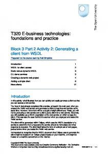
2. Notations 2.1. Use Case Maps The Use Case Map (UCM) notation is used to describe design specifications. UCMs are a graphical representation of the scenarios executing across a system. UCMs enable the user to grasp a system’s emerging behaviour without getting lost in execution details [1]. The basic building block of the UCM notation is the path. As a scenario is executed one can imagine a token traversing the path from the start to the end. UCM is a concurrent notation; there is no restriction as to the number of tokens that may traverse a given path or the position of any token on a path relative to any other token. UCM paths can also be overlaid on components, which represent functional or logical entities that are encountered during the execution of a scenario. Paths are refined to show more scenario detail through the addition of responsibilities. Responsibilities represent functions that need to be accomplished at given points in the execution of the scenario. UCMs also incorporate AND and OR forks and joins which show parallel and alternate scenario variants. As well, loops can be represented with a special loop construct. Figure 3 shows the UCM design for a distributed Ticket Reservation System (TRS). The TRS allows users to browse through a catalogue of events and seat availability, and to buy tickets using a credit card. The path for the main TRS scenario requires that a user first connect to the TRS before repeating a loop that incorporates two alternative sections describing either browsing or purchasing tickets. Once the user is satisfied, she exists the loop and requests to be disconnected from the TRS.
3
User
WebServer
Netware DisplayWeb
DisconnectWeb Disconnect DisplayNet ConfirmWeb ConnectWeb
Connect
ConfirmNet
Database ConfirmDatabase
CCReq DisplayDatabase VerifyCC
Figure 3: UCM of the Ticket Reservation System. The UCM notation enjoys a growing profile in the design community and is further bolstered by an industry-led effort to make UCMs an ITU-T standard as part of a recognized User Requirements Notation (URN) [2]. 2.2. Layered Queueing Networks Layered Queueing Networks (LQNs), previously called Stochastic Rendez-Vous Networks (SRVN), are used to specify performance models. LQNs allow for of an arbitrary number of client-server interactions. An LQN can thus model intermediate software servers and be used to detect software deadlocks and software as well as hardware performance bottlenecks. The layered aspect of LQNs also makes them very suitable for evaluating the performance of distributed systems [9]. LQNs model software and hardware resources as tasks and devices respectively. Communication consists of calls between tasks and are shown as messaging arrows. Synchronous messages are blocking calls that require a reply, and the sending task suspends execution until that reply arrives. Asynchronous messages are non-blocking calls that do not require a reply. Tasks receive service requests at designated interface points called entries. An entry may either be defined atomically or by activities. An activity is a smaller computational blocks with its own hardware service demands. An activity can make calls to entries in other tasks. Activities can be arranged in sequences, as well as in parallel (AND forks and joins) or alternative (OR forks and joins) configurations. An activity can also make repeated service calls in order to model repetitive behaviour. An LQN entry receiving a synchronous service request is responsible for either replying to it, or it may forward it to other entries. An entry that is forwarded to becomes responsible for eventually sending the reply back to the original caller. In the case of a forwarded call, the original
4
calling task remains blocked until it finally receives the reply at the very end of the forwarding chain. Figure 4 shows a graphical representation of the automatically generated LQN for the TRS. The large parallelograms are tasks and the small parallelograms are entries. Activities are represented by the small rectangles. The messaging arrows with a filled head represent synchronous service calls while the other arrows represent asynchronous calls. The dashed arrows with a filled head represent forwarded calls. User User_E1
User_A6
User_A1
User_A3
RefTask1_A1
Disconnect_hi d8
Connect_hid1 3* User_LH_48
User_A2
RefTask1 RefTask 1_E1
User_A5
User_A4
User_clone1 User_clo ne1_E1
User_clone1_A4 [User_clone1_E1]
User_clone1_ A1
User_clone1_ A3
User_clone1_ A2
WebServer WebSer ver_E1
WebSer ver_E2
WebSer ver_E3
WebServer_ A3 WebServer_ A1 ConnectWeb _hid3 WebServer_A2 [WebServer_E1]
+ WebServer_ A8
WebServer_ A4 WebServer_ A5
ConfirmWeb_ hid23
WebServer_ A7 +
OrJoin_Lqn_ A1
DisconnectW eb_hid10
WebServer_ A12
WebServer_A13 [WebServer_E2]
DisplayWeb_ hid13
WebServer_ A11
WebServer_ A9
WebServer_ A6
WebServer_A15 [WebServer_E3]
WebServer_ A14
WebServer_ A10
Netware Netware _E1
Netware_A1
Netware _E2
ConfirmNet_h id24
Netware_A3 DisplayNet_hi d15
Netware_A2 [Netware_E1]
Netware_A4 [Netware_E2]
CCReq CCReq_ E1
VerifyCC_hid 27
CCReq_A1
CCReq_A2 [CCReq_E1]
Database Databas e_E1 Database_A1 ConfirmDatab ase_hid25
Databas e_E2 Database_A3
Database_A4 [Database_E2] DisplayDatab ase_hid16
Database_A2 [Database_E1]
Figure 4: Graphical view of the LQN of the Ticket Reservation System generated by UCM2LQN.
3. Tool Support The UCM Navigator (UCMNav) is a UCM editing tool developed at Carleton University by Andrew Miga [5]. The UCMNav allows the user to draw and modify UCMs. Fields are provided to add additional comments and descriptions both for individual elements and for the overall design. These fields can be used to add resource demand figures and specify the system’s devices. The UCMNav can also be used to integrate multiple UCMs into an overall design.
5
The UCM2LQN converter is a generative tool that uses the UCMNav internal data representation to generate LQN performance models. It is integrated with the UCMNav and interprets the UCM paths into sequences of LQN elements. UCM2LQN assigns default values to performance information that is missing in the UCM design specification. The LQN models that are generated are saved as LQN text files that can be read by the LQNS and ParaSRVN solvers. LQNS is an analytic solver that breaks the LQN layers down into separate queueing network sub-models. The individual queueing networks can be solved analytically using mean value analysis (MVA). The MVA results for each sub-model are then used to fine-tune the MVA parameters for the other sub-models it is connected to and the MVA is performed anew. This process is repeated either for a maximum number of iterations or until the results converge on a user specified convergence value. LQNS cannot solve models that are not hierarchically decomposable [4]. ParaSRVN uses the ParaSol simulation environment, which can simulate multithreaded systems that support transactions and provides built-in statistics for monitoring simulation objects. ParaSrvn simulates LQNs by creating tokens for each call and following those tokens through the system. The performance metrics are arrived at by recording the wait times and other statistics for each token. Since ParaSRVN simulates the execution of the system rather than attempting to generate analytical solutions, it can deal with any type of model. LQNS and ParaSRVN both use the same input file format and generate similar outputs listing device utilizations, response times for activities and calls, and throughput figures.
4. Methodology The first step of E-PAD is to create a UCM design specification for the system. This is accomplished with the UCMNav editor. The design is then augmented with workload parameters. These parameters can either be known figures from systems of similar type [3], or if working within a component-based context they can be known from the components themselves [10], or they can result from using a performance budgeting approach to allocating maximum allowable response times [7]. The next step is to use UCM2LQN to automatically generate the corresponding LQN model. This is a generative step that creates non-code artifacts. It uses automation to bring performance modeling with the reach of average designers, a process that traditionally carries high overhead and requires specialized performance analysis knowledge. The LQN model is solved with LQNS and/or ParaSRVN. The performance results can be brought back into the design and used to: •
exploit the concurrency of the system
•
exploit the parallelism of the system
•
identify and flag performance-critical spots that will create software bottlenecks if not implemented carefully
•
evaluate the scalability of the system
•
guide the choice of components in a component-based development
6
5. Conclusions The E-PAD methodology proposed in this paper provides for the automated generation of a performance model from a design specification. The UCM2LQN tool makes a performance interpretation of an early system specification and fills in the missing performance information where necessary. This process is enhanced by using a component-based approach where the use of existing components includes known performance parameters for those components. The resulting layered queueing performance model can be solved or simulated using the LQNS or ParaSRVN tools in order to obtain performance results that can feedback into the design of the system. The generative approach used by the UCM2LQN tool to create performance models from design specifications is a step forward compared to traditional non-automated processes. E-PAD enables designers to get preliminary performance models without requiring them to become performance analysts. By removing that obstacle, this approach adds significant value to the SPE process.
6. References [1]
R. J. A. Buhr and R.S. Casselman, “Use Case Maps for Object-Oriented Systems”, Prentice Hall, 1996 [2] D. Cameron et al., “Draft Specification of the User Requirements Notation”, Canadian Contribution CAN COM 10-12 to ITU-T Study Group 10, November 2000 [3] M. Courtois and C. M. Woodside, “Using Regression Splines for Software Performance Analysis”, ACM Proceedings of the Workshop on Software and Performance (WOSP2000), Ottawa, Canada, 2000, pp. 105-114 [4] Greg Franks, “Performance Analysis of Distributed Server Systems”, Report OCIEE-00-01, Ph.D. thesis, Carleton University, Ottawa, Jan. 2000 [5] A. Miga, “Application of Use Case Maps to System Design With Tool Support”, M.Eng. Thesis, Department of Systems and Computer Engineering, Carleton University, Ottawa, Canada, 1998 [6] R. Schmidt and U. Assmann, “Concepts for Developing Component-Based Systems”, 1998 International Workshop on Component-Based Software Engineering, 1998 [7] K. H. Siddiqui, C. M. Woodside, “A description of Time/Performance Budgeting for UCM Designs”, The 5th Mitel Workshop (MICON2000), Mitel Networks, Ottawa, August 2000 [8] C. U. Smith, “Performance Engineering of Software Systems”, Addison-Wesley, 1990 [9] C. M. Woodside, J. E. Neilson, D. C. Petriu and S. Majumdar, “The Stochastic Rendezvous Network Model for Performance of Synchronous Client-Server-Like Distributed Software”, IEEE Transactions on Computers, Vol. 44, No. 1, Jan 1995, pp. 20-34 [10] C. M. Woodside, C. Hrischuk, B. Selic and S. Bayarov, “Automated Performance Modeling of Software Generated by a Design Environment”, to appear in Performance Evaluation, 2001 [11] ACM Proceedings of the Workshop on Software and Performance (WOSP’98), Santa Fe, USA, 1998 [12] ACM Proceedings of the Workshop on Software and Performance (WOSP2000), Ottawa, Canada, 2000