International Journal of Computer and Information Technology (ISSN: 2279 – 0764) Volume 02– Issue 01, January 2013
Generating operations specification from domain class diagram using transition state diagram BOUSETTA Brahim*, EL BEGGAR Omar, GADI Taoufiq Veille pour les Technologies Emergentes Laboratory Faculty of Science and Technology, Hassan 1st University Settat, Morocco *
[email protected]
Abstract—UML is nowadays the standard for modeling computer systems and used in software engineering to describe and model the different phases of software life’s cycle from requirements specification phase to the implementation of the code. Among the UML diagrams or models essential to produce this code is the design class diagram that determines the various business objects and their behavior or dynamic part, i.e. methods. These methods may be derived in a contemplative way from interaction models made in the preliminary phases of software modeling, such as: Sequence diagram of system’s internal behavior, collaboration diagram and state transition diagram. In 2000, the model driven architecture (MDA) approach proposed by the OMG promotes the usage of models throughout the entire development process. Starting from a so-called Computation Independent Model (CIM), different kinds of transformations lead to Platform Specific Models (PSMs). These PSMs can be used later to generate code for a specific platform. Within this context, this paper aims to facilitate the achievement of the implementation phase by providing an automatic transformation for generating the signatures of the different methods of the system’s complex classes through their transition’s state diagram. For this, we propose a model-to-model transformation taking as source models: the domain class diagram and transition’s state diagram, and then we generate the target model: the design class diagram using Atlas transformation Language (ATL). Keywords-component; MDE, State transition, ATL, Model transformation, Meata-modeling, Domain Class diagram;
I.
INTRODUCTION
A. Context UML is nowadays the standard for modeling computer systems [1], [2] and used in software engineering to describe the different phases of manufacturing software, from requirements specification phase to the implementation of the code. Different models are used during the development process and can be deduced from each other. The last phase of this process is performed largely on the design class diagram for determining the various business objects and their behavior, i.e. the treatment they carry out. These treatments or methods
www.ijcit.com
may be derived from other steps made in the earlier stages of modeling, such as sequence diagram of system’s internal behavior and state transition diagram for complex classes. Such modeling process can be improved by using model driven engineering (MDE) that promotes the usage of models throughout the entire development process. The Model Driven Architecture (MDA) is an implementation of the MDE initiated in 2000 by the OMG [1], [2]. Developing with this new approach starts from a so-called Computation Independent Model (CIM), different kinds of transformations lead to Platform Specific Models (PSMs). These PSMs can be used to apply a set of model-to-model or model-to-text transformation to derive automatically the final implementation of the system. The present paper subscribes in this area of research. We present an approach to automatically generate the methods signatures of system’s complex class through their transition’s state diagram. Thus, we propose a model-to-model transformation taking as source models, the analysis class diagram and transition’s state diagram, and then generate the design class diagram using Atlas transformation Language (ATL). The choice of ATL as transformation language comes from the fact that it extends the OCL (Object Constraint Language) [3] which remains a standard independent of models engineering development’s platform, Also, because the ATL is integrated within the eclipse/EMOF platform, that we used to implement the approach. In addition to that, the ATL offers the possibility of using several meta-model sources, while QVT takes only a meta-model of input processing. We also used the Eclipse’s ECORE meta-model that implements the MetaObject Facility- MOF [6] to represent the different metamodels used in this approach. To illustrate our approach, an example of soda machine distributor system will be presented at the different steps of the approach with different models and their meta-models as well as the transformation performed. The remaining of the paper is structured as following: In the next section, we present the source models of this transformation and their meta-models (state transition diagram’s meta-model and the domain class diagram’s meta-
29
International Journal of Computer and Information Technology (ISSN: 2279 – 0764) Volume 02– Issue 01, January 2013
model). Then, Section III is devoted to the target meta-model, design class diagram. While the next section shows the different transformation rules. In the end, we conclude this work with few prospects. B. Model Driven Engineering (MDE) : principles The model driven engineering (MDE) is a new approach of software development that gives more attention to modeling rather than programming. Indeed, it promotes the uses of models at different phases of software development and provides a variety of new paradigms: The model transformation (Model-to-model (M2M) and Model-to-text (M2T)) to automatically generate some or all of the software. It aims to up the abstraction by focusing on meta-modeling to define language for model’s expression (Domain Specific Modeling Languages – DSML) and validation. The main concept of this approach is the model that can be defined as an abstraction of a system that can provide answers to questions on it [4], [5]. The language used to create this model is called meta-model that is also in the form of a model known as modeling language [6]. During processing, the meta-models will validate instances of the source models and output model. A meta-meta-model is a model that describes a meta-modeling language, i.e. necessary model’s elements for defining modeling languages. It has also the ability to describe itself. The Model Driven Architecture – MDA is an implementation of MDE proposed by the OMG in 2001 [8] which is based on the UML standard [1], [2]. Software development in the MDA is principally based on with a Platform-Independent Model (PIM) of an application's business functionality and behavior, constructed using a modeling language based on OMG's Meta Object Facility (MOF) [6]. This model remains stable as technology evolves, extending and thereby maximizing software return on investment-ROI. Indeed, the MDA defines three levels of model’s abstraction [7]: •
A requirement view represented by the Computational Independent Model (CIM) describing the situation in which the system will be used and that is sometimes called a domain model or a business model;
•
An analysis and design view represented by platform Independent Model (PIM) presenting business domain system without considering architecture of the platform that will be used for implementation of the code,
•
And a code view represented by the platform Specific Model (PSM) that combines the view requirement specifications with a platform of execution used by the system [8].
Furthermore, MDA is based on UML that can be specialized or extended to express the required detailed models. This extension or specialization of UML can be performed by using the UML Profile, a standardized set of extensions (consisting of stereotypes and tagged values) defines a UML environment tailored to a particular use, such as modeling in a specific environment or on a specific platform. PIMs will be modeled using the profile for Enterprise Distributed Object Computing (EDOC) or Enterprise Application Integration (EAI), both near the end of their successful adoption processes. The UML profile for CORBA completed adoption by OMG in 2000; profiles for other platforms are in process. Regarding the transformation languages, we quote Query / View / Transformation (QVT) [9] which may be considered as one of the most appropriate model’s transformation language proposed by the OMG, and is now considered as a standard supported by several parties interested in the transformation of models [10]. Another model’s transformation language that is based on OCL and extends the QVT language and has become increasingly used is the ATL (Atlas Transformation Language [11], [12], [13], [14], [15]).
the the the the
The main objective of MDA is to develop sustainable models (PIM), independent of the technical details of the execution platforms (JEE, .Net, PHP, etc.), to allow the automatic code generation from Model (PSM) and to obtain a significant gain in productivity. This transition from PIM to PSM involves mechanisms for model transformation and model description of the platform (Platform Description Model
www.ijcit.com
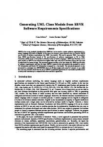
- PDM). This is, therefore, organized according to a development cycle "Y" introduced by the Model Driven Development - MDD. This new Architecture proposes a pyramidal form of abstraction’s organization. We find at the base of the pyramid the real world, and in the level M1 models representing this world. Meta-models for the definition of these models are the level M2. Finally, the meta-meta-model, unique and meta-circular, is shown at the top of the pyramid (level M3). However, many meta-models have emerged to provide their specific features of particular domain. To escape the threat to emerge independently and inconsistently this wide variety of meta-models, there was an urgent need to provide a general framework for their description. The logical answer was therefore to provide a language for defining meta-models which itself took the form of a model: it was the meta-metamodel MOF (Meta-Object Facility) [6]. The Figure 1 below shows this pyramidal architecture of MDA.
Figure 1: Pyramidal architecture of abstraction levels proposed by the OMG
30
International Journal of Computer and Information Technology (ISSN: 2279 – 0764) Volume 02– Issue 01, January 2013
C. Related works This paper subscribes in global approach that aims to automate the software engineering process by covering all the phases of the development starting from the requirement specification to code implementation. In [18] we presented a software engineering process based on UML for leading an IT project by specifying new artifacts and practices. The next work [19] introduced the model driven engineering approach and our proposed MDA approach to automate the software development process presented in [18] with different possible metamodels and transformation for the mapping between them. However, that paper focuses only on generating one of the most important PIMs increments of the analysis phase, the Sequence diagram of system’s internal behavior by a model transformation from the external one. This PIM is then used in [20] to generate automatically the code for a specific platform by a model to text transformation. In that paper a structured PSM model for the java platform was automatically generated and extended to support EJB capabilities using UML profiles technology. Finally, an executable implementation of the system for the JAVA platform was generated. The present paper completes our previous works for the automation of the entire proposed software development process by allowing generating the operation of complex classes through their state chart. This approach is especially efficient when modeling systems with classes that know an excessive change of their state more than interacting with other objects like soda machine distributor, cashier, some robots… II.
INPUT META-MODELS:
A. Transition state diagram’s meta-model: State Transition Diagram (TSD) has been used right from the beginning in object-oriented modeling. The basic idea is to define a machine that has a number of states (hence the term finite state machine) which define a set of values to attributes of the object at any given time. The machine receives events from the outside world, and each event can cause the machine to transition from one state to another. Thus this machine represents the class’s life cycle which is essential for representing and shaping the dynamics of the system and giving a formal definition of system’s behavior. Moreover, it is recommended to trace state diagram only for complex classes that have states excessively variables and are often coveted by other classes. In this case, it is appropriate to create a state diagram of these classes in order to study their state variation rather than study their interactions with other ones. Finally analyze its "unstable" behavior improves our understanding of the problem and allows furthermore detecting some object’s methods. So the state diagram allows us to complete the design class diagrams with methods that correspond to different actions and activities of the state diagram. The transition state diagram shows the dynamic of the class by presenting its different states and transitions between them. This transition between states is activated by receiving an event that is composed of parameters, condition and it executes one
www.ijcit.com
action or activity. A state has a limited time and can be simple or complex. A Complex state is composed of at least two other states. The transition from one state to another is performed by an external event. A class can also have an internal transition without change of state trigged by an internal event. Some of those internal events are predefined (entry, do, on event, after and exit). Event performs actions or activities that are transformed into operations or class methods. Old State -entry/action -do /activity -on event/action -exit/action
New State
Event (parameters) [condition]/activity
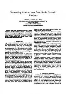
In some cases, computer systems have more operations outcomes from events rather than operations outcomes from the interaction between objects. In this case, transition states diagrams are best placed to find these operations than other interaction diagrams (collaboration diagram, sequence diagram of system’s internal behavior ...) such as Cash machine, Drink’s Distributor, Robot systems and classes under workflow process... The example of soda machines is among the interesting example which shows the importance of using the state transition diagram (Figure 2). Therefore, In Figure 3 we present the TSD metamodel based on the OMG’s MOF specifications [6]. In this metamodel, the StateMachine element start with a particular simple state the initialState and it includes a set of abstract state class which are two kinds: SimpleState and ComposanteState, this latter is composed by at least two other nested states. The transition between them is represented by the mean of a Transition metaclass that represents transition between two states (oldState and newState). A transition may be trigged when a condition was satisfied by an event that may contain parameters, the trigger event can be internal InternalEvent, represented by the default events: entry, do, exit, after or other events; or external ExternalEvent. Finally, an event performs action which will then be transformed to methods.
New coin/checkCoin arrival coin(num,datec)/CreateCons
Startup distributor
Wait coins Do/displayHello (loop)
abandon /destructCons
Insertion coins Entry/displayAmount Exit/displayTotal
Stop distributor abandon /destructCons Retreive drink /addCons
Delivery Drink do/displayThanks (loop)
Arrival drink /returnCoin
end insertion
Wait Drink After(5min)/destructCons
Figure 2: soda machine’s transition state diagram
31
International Journal of Computer and Information Technology (ISSN: 2279 – 0764) Volume 02– Issue 01, January 2013
B. Domain class diagram’s meta-model: A class diagram is one of the leading diagrams in a UML modeling. It allows you to dissect the system by showing its components (classes) then allowing a true object-oriented modeling. It provides a static view of the modeled system. Sometimes it is used for modeling the vocabulary of the system. This implies a decision that is based on which concepts or entities are part of the system and which concepts or entities are outside its boundaries. Class diagram is also used to build domain models, where all of the concepts that are present in the application domain are shown in the diagram, including the relationships between them. They can also be used to model collaborations among a set of classes, which work together to provide a collaborative behavior, or even to represent a database schema. It is possible to build class diagram at different abstraction levels and with different degrees of detail. For instance, analysis models, which are typically used in the first phase of the development process, have no implementation details, while design class diagrams would have implementation details. A domain model, is often referred as an analysis model, and might be represented by a particular kind of UML class diagram. It explains the structure of the application domain rather than the application structure itself. It focuses on the
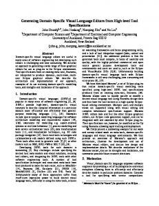
domain concepts, rather than on the software entities. While most of the elements will be present in the design model later on, new ones could even appear. UML class diagrams that commonly consist only of classes and their relationships can represent this kind of model. The classes, which represent the identified concepts in the domain, have only some attributes. Operations should not be present. Here, the most frequent relationship among classes is the association, which may have several adornments attached to its ends. An adornment may be a role name called also owned end or a multiplicity. In our meta-model presented in Figure 4 below, we have shown that the classes with their attributes and relationships. The methods will not be presented, and we will call it analysis class diagram. The element AssociationEnd refers to a role in an association accompanied with its multiplicity. III.
TARGET META-MODEL: DESIGN CLASS DIAGRAM.
While conceptual models are problem-oriented, design class diagrams reflect a solution-oriented structure. Indeed, while conceptual models are concerned with the entities and the relationships that are present in the problem domain, the design class diagrams focus on the way in which the solution is given. It contains full method’s signature.
Figure 3: Transition state’s meta-model.
www.ijcit.com
32
International Journal of Computer and Information Technology (ISSN: 2279 – 0764) Volume 02– Issue 01, January 2013
Classifier Association
0..1
-name : EString
classifier
-name : EString
PrimitiveType 1..1
association
DataType 2..* *
ownedEnds
Propoerty
Enumeration 0..1
type
Class 1..*
1..1
-isAbstract : EBoolean -isController :EBoolean
0..*
-name : EString -isDerived: EBoolean -default: EString
ownedattributes
superclass
Figure 4: Meta-model of domain class diagram
return 0..1 type 1
Classifier Association 0..1
-name : EString
classifier
-name : EString
PrimitiveType 1..1
association
DataType
2..*
Enumeration 0..1
Parameter name : EString Parameters 0..*
type
operations 0..*
Operation name : EString modifier: EString Visibility :EString
*
Class -isAbstract : EBoolean -isController :EBoolean
0..*
1..1
ownedEnds
Propoerty 1..*
ownedattributes
-name : EString -isDerived: EBoolean -default: EString
superclass
Figure 5: Meta-model of design class diagram.
www.ijcit.com
33
International Journal of Computer and Information Technology (ISSN: 2279 – 0764) Volume 02– Issue 01, January 2013
A design class diagram can be obtained following an analysis of interaction and collaboration between objects. Besides, the structural elements present in domain models, design class diagrams have other details that can be expressed in UML (such as all of the methods identified in the collaboration diagrams, navigation in the association ends, scope and type of the attributes and operations, and even new associations discovered during the design phase). Not all of the classes present in the conceptual model will be part of the design diagram of the system. Only those that participate in the object interactions in order to achieve the functionality required for the software system are included. Furthermore, other classes can be added to those existing ones in domain model such as the distributor class called also the system controllers. The Figure 5 presents the metamodel of the design class diagram. We can see that it contains the same element as the domain one and it is enriched with new elements such as operations.
Endogenous Transformation Meta-model Conforme To
Source model
Conforme To
Transformation
Target model
Exogenous Transformation Source Metamodel
Target Metamodel
Conforme To
IV.
Conforme To
GENERATING OPERATIONS SIGNATURES BY MODEL TRANSFORMATION
A.
Principe The MDA approach is based largely on creating a platform Independent Models (PIM) that can be mapped later to a platform specific model (PSM) and generate later the code for the suited platform. Transformation methods are indispensable to change the level of abstraction (vertical transformation) when transforming a PIM to a PSM or a PSM to PIM, or to keep the same level of abstraction (horizontal transformation) when transforming a PIM to PIM or a PSM to PSM. The transformation is an MDE approach of mapping or conversion from a source model to a target model according to their meta-models. If both source and target models conform to the same meta-model transformation, then, it is called endogenous. Otherwise it is exogenous. The Figure 6 illustrates these two types of transformation. In this paper, we proposed an exogenous transformation that accepts two separate meta-model sources. The first source meta-model is the transition state diagram which is a PIM describing the dynamic of some complex classes. The second input meta-model is the domain class diagram representing the business domain and system’s structure. The target meta-model is a design class diagram representing the implementation of the solution. The main objective of this transformation is to generate the methods signature from the transition state based on the event that activate the transition between them and feed the domain class diagram with this operations specification to get the design class diagram. B. Transofrmation Language: There are many languages for model transformation. We find generalist languages that are based directly on an abstract model representation. Application Programming Interface (API) of EMF is an example of this kind which is coupled with JAVA and allows manipulating the model as a graph.
www.ijcit.com
Source model
Transformation
Target model
Figure 6: Different types of transformation
Therefore the programmer should search the information in the model and gives an explicit order of the rules and manage the resulted objects. In purpose to make an abstraction of defining model transformation and make transparent the implementation details, a DSML was dedicated for model transformation. This approach requires defining a metamodel dedicated to transforming models and a tool allowing executing these model transformations. ATLAS Transformation Language (ATL) [16] is an example of this kind which will be used along this paper. It is a hybrid language (declarative and imperative) that allows defining a model to model transformation (called Module) in the form of a set of mapped rules. It allows also defining model to text transformation (called Query). The transformation takes one or many source models (defined with an Ecore metamodels). ATL is based on the main idea that the models are first-class entities. Therefore, and since everything is model, the transformations are also considered models. We can therefore apply their transformations, and it is one of the other important points about ATL. Indeed, it provides the means to achieve higher-order transformations (HOT). That is to say which changes the source and / or targets are themselves transformations. The OMG has defined the standard QVT (Query/View/Transformation) [17] for model transformation. The metamodel of the QVT is conforming to MOF and OCL and is used to navigate in the models. This metamodel is presented in tree sub-languages for model transformation characterized by the paradigm of implementation for transformation definition (declarative, imperative, hybrid).
34
International Journal of Computer and Information Technology (ISSN: 2279 – 0764) Volume 02– Issue 01, January 2013
C. Transformations performed: In this section, we present the main rules of the transformation performed to generate the design class diagram with the different classes and association deduced from the domain class diagram and using the transition state diagram to generate the method’s specification. Main Transformation rules (Figure 8): From the Domain class diagram meta-model, all the present elements with their instance will be mapped to the corresponding elements in design one. Thereby, an analysis class is transformed into a design class keeping its attributes, modifiers and its associations. However, the meta-model of the transition state diagram allows us to transform the activities to methods that will feed into the corresponding design classes of the target diagram. In fact, the transition state diagram presents the object state change when receiving an event. When this event occurs, the object will execute an activity to respond. Supplement information and data needed to accomplish this task will be given as parameters of this event. Therefore, we have all the necessary elements to generate clearly and correctly the method signature. Thus, for each transition between two states, we will map the activity to an operation in the corresponding domain class. To complete the specification of the operation we will look for the parameters and returned values from the event that has activated the transition.
helper context ACD!Property def : toStringProperty(): String = if self.visibility.oclIsUndefined() and self.modifier.oclIsUndefined() then self.name+':'+self.type.name else if self.visibility.oclIsUndefined()then self.modifier+' '+ self.name+':'+self.type.name else self.visibility + ' '+ self.name+':'+self.type.name endif endif; helper context TSD!Action def : getSignature(): String = if self.return.oclIsUndefined() and self.visibility.oclIsUndefined() then self.name+'('+self.getParametres()+'):void' else if self.return.oclIsUndefined() then self.visibility+''+self.name+'('+self.getParametres()+'):void' else self.name+'('+self.getParametres()+'):'+self.return.name endif endif;
rule ACDClass2DCDClass{ from s:ACD1!Class to t: DCD!Class ( name