Generating Functional Mockup Units from Software Specifications
Uwe Pohlmann, Wilhelm Sch¨afer
Hendrik Reddehase, Jens R¨ockemann, Robert Wagner
Software Engineering Group, Heinz Nixdorf Institute, University of Paderborn, Germany [upohl|wilhelm]@upb.de
Solunar GmbH, G¨ utersloh, Germany [reddehase|roeckemann]@solunar.de
[email protected]
Abstract This paper presents an approach to use the Functional Mockup Interface (FMI) for integration of classical controller specifications and statechart based specifications of real-time critical message exchange protocols. The Functional Mockup Unit (FMU) is automatically generated from the specification. Using the generated FMU we are able to exploit simulation facilities as provided by Modelica/Dymola. Keywords: Systems Engineering, Software Engineering, MechatronicUML, FMI, FMU, Modelica
1
Introduction
In today’s globalized world market forces demand products to provide for more and more unique features. In so-called mechatronic or embedded systems these features are often realized (mainly) by software. For example, many new features which were recently introduced in the automotive industry are largely software driven. In addition, very advanced new features will depend on extensive communication between currently still independently operating individual components. For example, intelligent lighting systems in cars will combine information about the environment obtained from their own sensors with those collected by other cars to save energy but also to avoid glaring other drivers. Similar examples exist for transportation systems in general but also for household appliances or in the production industry [25]. Here, possible significant energy savings are one main motivation to introduce so-called smart grids. The resulting high amount of software enabling DOI 10.3384/ecp12076765
communication between a large number of components combined with the software controlling individual components makes those systems more complex than today. This requires significant changes in the way software is developed today. This is especially true as the software controlling individual components is usually dealing with continuous variable values and developed by control engineers whereas software controlling communication is handling discrete input and output signals often using asynchronous communication and is developed by software engineers. In addition, electrical and mechanical engineers bring in expertise about the underlying hardware system constraints which have to be considered when developing the software. As these systems are usually deployed in safetycritical environments, high quality of the software is an absolute must [21]. However, in the past, an overall validation of systems under construction was not possible until implementations had been finished, i.e., after all hardware and software parts had been built and integrated into the final product. The above mentioned different disciplines use their own models and formalisms to describe the corresponding parts of the system under development, e.g. feedback controllers are described using differential equations and communication protocols are described using statecharts. This development process hinders early (formal) verification and simulation of system models to detect errors in the design phase as early as possible and to avoid costly error removal in later development stages. In this paper we focus on supporting simulation based on model-driven development especially considering cross-discipline development between control and software engineering. In contrast to other approaches like [22, 8, 26], we use
Proceedings of the 9th International Modelica Conference September 3-5, 2012, Munich, Germany
765
Generating Functional Mockup Units from Software Specifications
a discrete system model which enables the detailed specification of timing issues when speci fying communication protocols, because message transfer specified by those protocols is real-time critical. Proper functioning of the system does not only depend on the correct order of messages sent and received but also on their timely delivery. This paper presents how we employed the Functional Mockup Interface (FMI) and the Functional Mockup Units (FMU) in order to integrate discrete model-based real time protocol specification with controller design and appropriated simulation facilities using Modelica/Dymola. The approach has been developed as part of the ENTIME project (ENTIME is the German acronym for ’Design Methods for Intelligent Mechatronics’). The project aims at the development of a seamless methodology reaching from conceptual design to concrete implementation of mechatronic systems. It is carried out in close cooperation with nine industrial partners. To support simulation of the physical models and corresponding feedback loops together with specifications of real-time protocols, the main challenge was to provide the needed tool support, because the project collaborators use different modeling and simulation tools in their industrial practice. The paper is organized as follows. In the next section we illustrate the use of MechatronicUML, a domain specific modeling language enabling protocol specifications including sophisticated realtime constraints. The example which we use in the paper, is a miniature robot called BeBot which is a small mechatronic systems with a focus on ad-hoc communication. In Section 3, we give a brief and informal introduction to the concepts of the FMI standard, sketch our implementation of MechatronicUML according to the FMI standard for model exchange by means of the example, and present our tool support. Section 4 discusses related work in more detail. The paper closes with a conclusion and an outlook on future work.
2
Specification of Protocols
by the German national science foundation since 2002 (http://www.sfb614.de/en/).
2.1
Running Example
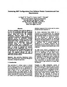
The example is the scenario of a so-called obstacle avoidance maneuver which is performed by a BeBot. BeBot [11] is a sophisticated intelligent miniature robot, developed by the Heinz-Nixdorf Institute. Figure 1 shows a picture of a BeBot. In our scenario, the BeBot uses three sensors which detect obstacles in front, left and right of its current position. Further, the BeBot has a gyroscope which measures its current angle position with respect to the outside world. Three components of the BeBot are active when it performs obstacle avoidance. These components are (1) an exploration component which starts or stops the exploration of the environment, (2) a navigation component which steers the BeBot around an obstacle based on the given sensor inputs and (3) an obstacle detection component which receives the input from the three sensors and transforms them into corresponding messages which are received by the navigation component.
Figure 1: BeBot Robot [11] As a consequence, the decision if and how an obstacle avoidance maneuver has to be performed depends on (extensive) asynchronous communication between these three components. For example, the navigator which knows the actual angle to the outside world, informs the obstacle detection component which sensor values are relevant. The obstacle detection component must not send messages when a turn is performed, because sensor values are not correct when the BeBot spins.
The specification language which we use is called MechatronicUML [3]. It has been developed by a large joint project between engineers and people from computer science. The project is the collaborative research center self-optimizing sysFigure 2 illustrates how a BeBot will find its tems in mechanical engineering which is funded way out of the shown maze. 766
Proceedings of the 9th International Modelica Conference September 3-5, 2012, Munich Germany
DOI 10.3384/ecp12076765
Session 6D: FMI Standard II
BeBot_SW
90° = North
sender
receiver Exp
linear_speed
Exploration
BeBot
left
+/- 180° = West
angular_speed
front
-90° = South
0° = East
right
Navigation Obstacle Detection
slave
actual_angular
master
Figure 3: Component Type of the BeBot Software
Figure 2: BeBot Obstacle Avoidance Maneuver
2.3 2.2
Structure Model
In MechatronicUML the system model is structured hierarchically and consists of either atomic components or of structured components. Atomic components implement their behavior directly and structured components are a composition of other components. The component model of MechatronicUML differs from other componentbased approaches, like [27], as MechatronicUML employs active components, i.e. the behaviour of each component is specified by a real-time statechart (see below) and executed by a single thread [3]. Each component has interaction points, called ports for accessing their functionality. Discrete ports, shown as rectangles, are used for sending and receiving asynchronous messages. Each message is typed over a message type. Further, discrete message ports have the causality in , out , or in/out . Discrete in-ports can only receive messages, discrete out-ports can only send messages and in-out-ports can receive and send messages. A continuous port, shown as a triangle is either a continuous in-port , or a continuous out-port . It sends or receives signal values which are typed as Boolean, Int, or Real. Figure 3 shows the internal structure of the BeBot SW component. It consists of three atomic components. The component Exploration is responsible for starting and stopping the exploration scenario. It is connected via its port sender to the component Navigation. The Navigation component is responsible for actuating the BeBot. It can set the linear speed and the angular speed of the BeBot. The Navigation component is connected to the ObstacleDetection component via its discrete port master. The ObstacleDetection component transfers the continuous signal values of the sensors front, left, and right to asynchronous messages. These messages inform the Navigation component if it has to perform an obstacle avoidance maneuver. DOI 10.3384/ecp12076765
Real-Time Properties
Real-Time properties are specified by clocks. In MechatronicUML a clock is a first-class realvalued entity and is used to synchronously measure the duration of time during execution. It can be reset to zero, which is marked by the keyword reset, with any state- or transition-action. At the beginning of the simulation clocks start with a zero-value. In contrast to delayed transitions of State Graph2 [22], or the after, before-construct of Stateflow [23], or the relative time event after of UML, a clock is not automatically reset when the system state changes. At any point in time, a clock can be read. The value of the clock represents the continuous-time since the last reset [2]. This semantics simplifies the specification of more complex real-time behavior and constraints. It is possible to compare clock values with time constants. We use clocks to specify transition guards, transition deadlines and time invariants of states.
2.4
Discrete Behavior Model
MechatronicUML uses Real-Time Statecharts to specify protocols of message exchange between different components, i.e. the order of message invocation and its corresponding time constraints. Besides elements from UML state machine formalism Real-Time Statecharts use syntactic elements like clocks and corresponding clock constraints as extended transition guards as defined by timed automata. In MechatronicUML each discrete port has its own statechart. The behavior of a component is given by the parallel composition of all statecharts of all its ports. In addition, it is possible to add synchronization channels like in timed automata to synchronize the behavior of the different port statecharts. Time-invariants from timed automata constrain when and how long a statechart is allowed to stay in a particular state. We define the maximum time for evaluating and executing a transitions by a deadline. We use clocks as guards of
Proceedings of the 9th International Modelica Conference September 3-5, 2012, Munich, Germany
767
Generating Functional Mockup Units from Software Specifications
transitions, deadlines of transitions, and time invariants of states. The operational semantics of Real-Time Statecharts is formally defined by [12] and is based on timed automata.
Navigator receiverExp Stop
master Halt
It enables the application of formal verification techniques like real-time model checking [14] with tools like UPPAAL [4]. For instance we specify in our example in Figure 4 the safety property that each turn maneuver may not last longer than 5 seconds. Therefore we use the time invariant c0 < 5. Figure 4 shows the Real-Time Statechart of the It consists of the parallel composition of the port statecharts receiverExp and master. The statechart in region receiverExp describes how the received messages from component Exploration are processed. At the beginning the statechart is in its initial state Stop and the parallel statechart master is in the state Halt. When the upper statechart gets the asynchronous message start the outgoing transition fires, if the synchronization channel go is available. The synchronization channel go is available if the sender transition, marked by the “!”, and the receiving transition, marked by the “?” can fire. If both transition can fire both transitions fire together in an atomic way. This means either both fire or none of them. Because there are no more conditions on the transitions they fire and the statechart gets in the states Start and Go. Navigation component.
start go! /
1
2 Start
stop() halt! /
1 var: Integer linear_speed, angular_speed, ref_angular, Real actual_angular; cl: c0; NoObstacleLeft / 1 go? / stopDetectLeft
1
halt? / 4
Go
entry / {linear_speed := 0.1, angular_speed := 0} exit / {linear_speed := 0} 1 / detectLeft 1 TurnFinished Minus90 c0 < 5
3 2
NoObstacleRight / stopDetectRight
Turn0 c0 < 5 entry / {angular_speed := 1, ref_angular := 0} 1 {reset: c0}
[actual_angular == ref_angular] / turnFinished / detectRight obstacleFront /
1 TurnFinished 90 c0 < 5
[actual_angular == ref_angular] / [actual_angular == [ref_angular == 0] / turnFinished ref_angular] / 1 1 ObstacleFront turnFinished Turn90 1 entry / entry / TurnMinus90 {linear_speed := 0} {angular_speed := 1} 3 {reset: c0} entry / 2 {angular_speed := 1, [ref_angular == 90] / [ref_angular == -90] / ref_angular := -90} stopDetectRight stopDetectLeft {ref_angular := 90}
Figure 4: Real-Time Statechart the Navigator
2.5
Asynchronous Communication
The shown Real-Time Statechart formally defines the protocol definition of the message exchange and the corresponding timing constraints. Messages are sent when a transition fires. Messages which should be sent are shown behind the slash (/) and messages which should be consumed are shown before the slash. The connector may have a delay or a message could be lost. For the sake of simplicity of the figure above and due to lack of space, we omit the specification of the connector here. The receiver port of a message stores a received message in a mailbox. This is implemented as a queue and has a fixed size which is defined by the modeler during design time. Each message type has its own mailbox. Thus, the receiver can test directly if a needed message is available without searching the whole queue. Each message type could have an arbitrary number of parameters, which are packaged in the message when a transition fires. The receiver transition can read and process the parameters when it fires and consumes the message. Messages remain in the mailbox until a transition consumes and destroys it.
When the statechart master enters the state Go the output signal linear speed of the BeBot is set to the value 0.1 and the angular speed is set to 0. In the state Go the BeBot drives forward until the ObstacleDetection sends the message obstacleFront. In this case the BeBot turns right to a southward direction and drives forward until the left sensor signals that there is no more obstacle at the left side. If there is no more obstacle, the BeBot turns back in an eastward direction and drives forward until the next obstacle occurs in front of it. If there is an obstacle at the left side until the BeBot reaches the corridor boarder, the BeBot performs a U-turn and drives forward until the right sensor 2.6 Further Features of signals that there is no more obstacle at the right MechatronicUML side. These steps are carried out in a loop until the Exploration component sends the stop message. As explained, MechatronicUML [3] mainly focuses on the discrete parts of systems. The language 768
Proceedings of the 9th International Modelica Conference September 3-5, 2012, Munich Germany
DOI 10.3384/ecp12076765
Session 6D: FMI Standard II
especially addresses the specification of complex communication protocols with hard real-time requirements [9]. The structure of a mechatronic system is defined by a component-based development approach. It is possible to distinguish between discrete software components and continuous software components like controllers. MechatronicUML has clear interfaces between discrete system parts and continuous system parts. The behavior of continuous components including their communication protocols is specified by an extension of our Real-Time Statecharts in the sense of hybrid automata. However, in contrast to hybrid automaton approaches [1, 19] we abstract from detailed definitions of controllers. This abstraction together with some constraints on the parallel composition of port statecharts enables formal verification of the behavioral specification using model checking. We employ the model checker UPPAAL to verify safety properties like deadlock freeness, state reachability or end-to-end response time. MechatronicUML models can be verified automatically. We also prove by model checking that a mailbox will not overflow (see above). However, formal verification is beyond the scope of this paper and we refer to [15, 13] for further details.
3
Generating FMUs Software Specification
from
This section shows how to generate an FMU.
3.1
FMI/FMU Fundamentals
Using different tools when designing the models leads to compatibility problems when you want to simulate all models in combination. To address this problem, the ITEA2 project MODELISAR has defined the FMI as an open standard for model exchange and co-simulation between multiple software systems. The FMI is used to create an instance of a model which can be loaded into any simulator providing an import function for FMI [7]. The FMI for Co-Simulation allows to couple several simulation tools [6]. A software instance compatible to the FMI is called an FMU. An FMU is basically a zip-archive with a “*.fmu” file extension. The information required for the simulation environment is collected DOI 10.3384/ecp12076765
in an XML-file called modelDescription.xml. In addition, this file also includes a list of all variables available for data exchange between the simulator and the FMU. Furthermore, the standard defines functions that are used for the interaction between a model and the simulator. To provide an FMU, the FMU provider has to implement these functions using the C language.
3.2
Generating C-Code MechatronicUML
from
This section sketches the C-code generation techniques for MechatronicUML models. The generated code may be used for a concrete microcontroller target platform or – as this paper shows – for an FMU implementation. 3.2.1
Generating C-code Structure Model
from
the
For each atomic component of the MechatronicUML model, we generate a header file and a corresponding implementation file. A component is mapped to a structure containing pointers to nested sub-components, variables, and clocks required for the associated statechart. In addition, corresponding code for the ports is generated. The discrete port implementation is used for inter-component communication. For this purpose, a discrete port implements an array of message queues. A queue stores messages of one specific type. For parametrized message types additional structures are generated in order to encapsulate the parameter values. For continuous in-ports we generated a variable with the causality input and for continuous out-ports we generate a variable with the causality output. The continuous port type is mapped to a corresponding FMI data type, e.g. Boolean to fmiBoolean. Via the input and output variables the FMU can be connected to other FMUs or Modelica/ Simulink components. Our code is intended to run also on small 8-bit processors with only a few kilobytes of memory. This is too little to support both a real-time operating system and the control software. Hence, the control software is executed standalone on the processor and to support multiple communicating components on one processor, the components are processed in a cycle using a simple task loop implementation. Note that for future work we will intro-
Proceedings of the 9th International Modelica Conference September 3-5, 2012, Munich, Germany
769
Generating Functional Mockup Units from Software Specifications
duce a real-time operating system with more sophisticated task management and scheduling features for larger systems with 16- and 32-bit processors. Listing 1 shows the execution sequence of our example. The information about a component is passed as an argument, allowing for multiple components of the same type to exist in one environment. In every processing cycle, a component statechart may exchange messages with other components by sending and receiving them. After every component has been processed, a synchronization step is performed where raised events are delivered to the target components. ... // e x e c u t e component b e h a v i o r exec navigation ( comp navigation ) ; exec exploration ( comp exploration ) ; exec obstacle detection ( comp obstacle detection ) ; // e x e c u t e message e x c h a n g e sync ( c o n n e c t o r s e n d e r r e c e i v e r E x p ) ; sync ( c o n n e c t o r m a s t e r s l a v e ) ; ...
Generating C-Code from Discrete Behavior Model
the
There are several implementation techniques for statecharts, but in most cases all the techniques are variants and combinations of (1) the state table, (2) the object-oriented state design pattern, and (3) the simple switch-case statement implementations. (1) The state table implementation maps directly to a state table representation in the code. As it is not hierarchical, it needs extensions for nested states and parallel regions and requires a large state table representation with a complicated initialization. Hence, the code is less readable. (2) The state design pattern simplifies the implementation of statecharts. However, it has also to be extended for hierarchical statechart implementations. In addition, the implementation is straightforward in C++, but it is rather complex in C, because of the needed mapping for inheritance and polymorphism. Therefore, we decided to generate nested switch-case statements (3). The implementation technique of switch-case statements is quite simple, it can be easily coded in C, and it has a small memory footprint since only one state variable is necessary to store the current state of a state machine. Furthermore, 770
void e x e c u t e m a s t e r ( c o m p n a v i g a t i o n ∗ comp ) { ... switch ( r e g m a s t e r ) { ... case STATE NAVIGATOR OBSTACLEFRONT: i f ( r e f a n g u l a r == 9 0 ) { . . . } e l s e i f ( r e f a n g u l a r == −90) { . . . } e l s e i f ( r e f a n g u l a r == 0 ) { // s t a t e change r e g m a s t e r = STATE NAVIGATOR TURNMINUS90 ; // e n t r y a c t i o n s angular speed = 1; r e f a n g u l a r = −90; } ...
Listing 2: Excerpt from navigation.c
Listing 1: BeBot Execution Sequence
3.2.2
nested switch-case statements allow us to implement hierarchical statecharts in a quite intuitive and readable way, which ensures traceability between the model and the generated code. Listing 2 shows a code excerpt from the generated program for the BeBot example shown in Figure 4. It gives an impression of the generated C-code for a transition from state ObstacleFront to state TurnMinus90.
For each region of a statechart, we declare an Integer variable to keep the current state of this region. Within each case-statement, a sequence of mutually exclusive if-statements is used to determine whether one of the state’s outgoing transitions can fire. In order to enable a transition, the existence of events and Boolean expressions generated from conditional guards, clock guards, and synchronization channels have to be evaluated. As transitions have priorities in MechatronicUML to prevent non-deterministic behavior, the generator sorts the transitions according to their priorities before generating the appropriate code. If a transition is enabled, it fires, i.e. the new state is set and the appropriate exit and entry actions are executed. A state may also contain do-actions and inner regions which are executed if no transition is enabled. For this case, a final else-block is created. Note, the presented program is executed once in each cycle. In order to use the generated C-code for an FMU implementation, we have to implement the required interfaces from the FMI standard.
3.3
FMI/FMU Wrap Up
We employ the FMU SDK from QTronic [16]. Figure 5 shows the relations and dependencies between the FMI standard, the QTronic FMU SDK, and our statechart implementation.
Proceedings of the 9th International Modelica Conference September 3-5, 2012, Munich Germany
DOI 10.3384/ecp12076765
Session 6D: FMI Standard II
Figure 5: Implementation Dependencies The basic implementation of the FMI is provided by the FMU SDK. To implement MechatronicUML, our code generator creates a header file and an implementation file for each component taking the FMU SDK into account. The FMU SDK implements the FMI standard by delegating some of the tasks to supplementary functions that have to be implemented by the user. In our case, these implementations are also generated automatically by our code generator. The most important function is eventUpdate, as it is used to execute the statecharts. Since the eventUpdate-function is called by the FMIfunction fmiEventUpdate whenever an event occurs during a simulation, we are able to react on changes in the simulation model. We use Time Events from the FMI to control the execution of a statechart at a regular interval and map each clock to an fmiReal variable. Since the current simulation time is passed to the FMU as a parameter, the current simulation time is assigned to the clock variable to reset a clock. Evaluating is done by calculating the elapsed time since the last reset. The difference between the current simulation time and the affected clock variable is used to evaluate clock constraints, deadlines and invariants upon appropriate actions are taken. In the FMI standard, direct access to the data stored within the model is not possible, even if the source code is provided. Instead, a reference number is associated with each variable in the description file. Therefore, the FMU SDK stores variables of the model in four arrays of the types fmiReal, fmiInteger, fmiBoolean, and fmiString and references them by using indices. This is an efficient implementation of the FMI standard, but it is not useful for target-specific code that does not serve as an FMU implementation. Further, it is not easy to read and to understand the code. Therefore, we generate placeholders for the variables of our model. For the FMU implementation we generate preprocessor macros, which map the placeholders to FMU SDK compliant array access statements. DOI 10.3384/ecp12076765
Figure 6: EmbeddedModeller In case of other targets, e.g. microcontrollers, we generate preprocessor macros mapping the placeholder to more suitable structures and variables.
3.4
Tool Support
We provide our tool support in form of an Eclipse modeling tool suite which is called EmbeddedModeller. The EmbeddedModeller provides several diagram editors and supports software specifications based on MechatronicUML as explained in the previous sections. Figure 6 shows the editors for Real-Time Statecharts and structured component diagrams. For generating C-code and the corresponding FMU description file, we used a template-based code generator framework. To create the FMU with all resources, the batch script provided with the FMU SDK is executed. Firstly, the batch file creates a temporary directory with the desired directory structure for the FMU under construction. Secondly, it compiles the sources and copies all needed files to the corresponding folders. Lastly, the batch packages the processed directory and saves it within the *.fmu file. To simulate the designed BeBot software, we generated the FMU for our software specification BeBot SW and created the Modelica model of the mechanical and control engineering parts of the BeBot within Dymola. The FMU was imported and connected to the hardware model of the BeBot. Since the continuous ports of the MechatronicUML serve as an interface to continuous components in general, we are able to connect our FMU, i.e. our discrete software component, to the provided BeBot feedback controllers. We simu-
Proceedings of the 9th International Modelica Conference September 3-5, 2012, Munich, Germany
771
Generating Functional Mockup Units from Software Specifications
lated the integrated model in Dymola successfully. Note, our approach is not limited to Modelica / Dymola as the FMI standard is tool-independent. Therefore, it is possible to simulate software specifications with any other simulation tool which supports the FMI model exchange standard.
4
Related Work
communication. Timing behavior is supported in a limited way, as transition firing could be constrained to a time interval from the moment when the source state of the transition is entered. In MechatronicUML we use, like timed automata, clocks, clock constraints, time invariants, and deadlines to specify and constrain the timing behavior of our models. Messages are only available within a statechart in SimulationX. They do not support an arbitrary number of parameters, and messages are lost when a transition cannot react on the event immediately. Therefore, it is difficult to specify coordination of distributed components. SimulationX generates Modelica algorithm code from its state machines.
This section presents related work. We focus on approaches which can be used to simulate hybrid systems and where the discrete behavior is state-based. Further, we currently use the FMI for model exchange and not for co-simulation. Therefore, we do not discuss other approaches ModelicaML is a UML Profile [26] which enfor co-simulation or distributed simulation like ables to use UML Classes and Properties to specCODIS [5], TISC [20] or FMI co-simulation [6]. ify Modelica models. State-based behavior is modeled by UML state machines. The code gener4.1 Statecharts in Modelica ation mechanism supports nearly all UML state Currently, state-based behavior can be modeled machine constructs [24]. The Modelica code is in Modelica with the library State Graph2 or al- generated like SimulationX to the Modelica algogorithmic code is generated from SimulationX or rithm section. As UML has no concept for clocks, clock constraints, time invariants, and deadlines, ModelicaML. ModelicaML does not support them either. AsynState Graph2 is a Modelica library [22] which chronous messages between components can be provides classes for states (Step), hierarchical simulated via an external C-function [24]. As and parallel behavior (Parallel ), and transitions ModelicaML has all freedoms of Modelica, it is not (Transition). With these elements it is possipossible to verify the resulting models efficiently. ble to model complex behavior like Harel’s wrist watch example. In contrast to MechatronicUML, StateGraph2 has no concepts for clocks, clock constraints, time invariants, and deadlines to specify and constrain timing behavior. A modeler 4.2 MATLAB Simulink/Stateflow could manually implement such behavior in Modelica. Further, State Graph2 has no concept for MATLAB has an own state-based modeling lanasynchronous message-based communication. We guage called Stateflow, which can be combined are currently working on such a library extension. with its simulation platform Simulink. Stateflow However, as State Graph2 is modeled with equa- supports many features from UML state machines tions and these equations are sorted before the and can be combined with the whole capabilities model is simulated, the modeler can hardly influ- of the MATLAB platform via its action language. ence the resulting C-code generated by Dymola. It is only possible to define formal semantics for So, it is difficult to compare this code with real restricted Stateflow models [17]. Stateflow does target source code. The FMI C-code is the same not provide first class modeling entities for specias the target source code except for the interface fying timing behavior, except simple after and bedefinition . fore statements. Stateflow does not provide a conSimulationX has its own state-based language cept of buffering messages. It is possible to model which follows the ideas of UML state machines such elements with a combination of Simulink and and supports a subset [8]. In contrast to Real- Stateflow blocks, but this is complex, error prone, Time Statecharts, SimulationX does not support and hard to maintain manually [18]. It is possible parallel behavior, timing behavior, and coordina- to load FMU using the separate FMI toolbox of tion of distributed components by asynchronous Modelon [10]. 772
Proceedings of the 9th International Modelica Conference September 3-5, 2012, Munich Germany
DOI 10.3384/ecp12076765
Session 6D: FMI Standard II
5
Conclusion and Outlook
This paper shows how it is possible to generate FMUs from a formal software specification language for cyber-physical system. As a result it is possible to perform software-in-the-loop tests by numerical simulation of hybrid systems. We describe the following problem that arises when providing a methodology and tool support reaching from conceptual design to concrete implementation of cyber-physical systems: The approach should support the overall system simulation for different industrial partners in a heterogeneous design tool environment. The partners provide simulation models for mechanical and control engineering parts of the system, but software simulation models are missing. The transformation of software specification to FMUs solves this problem. As the main contribution, we describe how a software specification in MechatronicUML can be automatically translated to FMUs maintain the original MechatronicUML semantics and, thus, the verification results. In particular, we map the component-based structure, the asynchronous communication in form of Real-Time Statechart, and real-time properties in MechatronicUML to C-code, which is wrapped by the FMI. We implemented the generation of FMUs from a given MechatronicUML model using a modeldriven transformation approach. This combines the modeling and formal verification strengths of MechatronicUML with the advanced simulation capabilities of simulation tools like Dymola or Simulink. As a result of numerical errors we cannot guarantee that in different FMI import tools the different simulation runs have the same behavior. Therefore, the formal verification is important because it proofs every possible simulation run and guarantees that all paths are conform to the specification. It is up to further research to proof that our generation is correct and keeps the verified properties. The shown transformation approach should be interesting for anyone who wants to test formal software specification by simulation against a model of the physical system. A transformation against the FMIs could be performed for other formal software specification languages like Petri nets for flow analysis or stochastic software models for testing performance or failure rates. Hereby, it would be possible to combine the strength of formal analysis and numeric simulation. DOI 10.3384/ecp12076765
For future work, we plan to develop a concept to allow for communicating via messages between several FMUs. Further, we want to generate code against different hardware platforms to analyze the timing behavior. We want to integrate the behavior of an underlying middleware or real-time operating system into the simulation. We may use co-simulation for this purpose. The simulation of complex cyber-physical systems requires much computing time. We want to compare the performance of native Modelica simulations with integrated FMU simulations and try to enhance the performance of hybrid simulations. Currently, it is not easy to interpret the simulation results. Here a bisimulation concept would help. To show the result, a simulation run could be visualized in the statechart or the message exchange could be visualized by sequence diagrams. Acknowledgments This work was developed in the project ’ENTIME: Entwurfstechnik Intelligente Mechatronik’ (Design Methods for Intelligent Mechatronic Systems). The project ENTIME is funded by the state of North RhineWestphalia (NRW), Germany and the EUROPEAN UNION, European Regional Development Fund, ’Investing in your future’.
References [1] R. Alur, C. Courcoubetis, N. Halbwachs, T.A. Henzinger, P.H. Ho, X. Nicollin, A. Olivero, J. Sifakis, and S. Yovine. The algorithmic analysis of hybrid systems. Theoretical computer science, 138(1):3–34, 1995. [2] R. Alur and D. L. Dill. A theory of timed automata. Theoretical Computer Science, 126:183– 235, 1994. [3] S. Becker, C. Brenner, S. Dziwok, T. Gewering, C. Heinzemann, U. Pohlmann, C. Priesterjahn, W. Sch¨afer, J. Suck, O. Sudmann, and M. Tichy. The mechatronicuml method - process, syntax, and semantics. Technical Report tr-ri-12-318, Software Engineering Group, Heinz Nixdorf Institute University of Paderborn, 2012. [4] G. Behrmann, A. David, and K. Larsen. A tutorial on uppaal. Formal methods for the design of realtime systems, pages 33–35, 2004. [5] F. Bouchhima, G. Nicolescu, E. M. Aboulhamid, and M. Abid. Generic discrete-continuous simulation model for accurate validation in heterogeneous systems design. Microelectron. J., 38(67):805–815, June 2007.
Proceedings of the 9th International Modelica Conference September 3-5, 2012, Munich, Germany
773
Generating Functional Mockup Units from Software Specifications
[6] MODELISAR Consortium. Functional mock- [17] G. Hamon and J. Rushby. An operational seup interface for co-simulation. version 1.0, 2010. mantics for Stateflow. International Journal on www.functional-mockup-interface.org. Software Tools for Technology Transfer (STTT), 9(5):447–456, 2007. [7] MODELISAR Consortium. Functional mock-up interface for model exchange. version 1.0, 2010. [18] C. Heinzemann, U. Pohlmann, J. Rieke, www.functional-mockup-interface.org. W. Sch¨afer, O. Sudmann, and M. Tichy. Generating simulink and stateflow models from [8] U. Donath, J. Haufe, T. Blochwitz, and T. Neisoftware specifications. In Proceedings of the dhold. A new approach for modeling and veriInternational Design Conference (DESIGN 2012) fication of discrete control components within a Dubrovnik, Croatia, May 2012. Modelica environment. In Proceedings of the 6th Modelica Conference (Modelica 2008), Bielefeld, [19] T.A. Henzinger. The theory of hybrid automata. pages 269–276, 2008. In Logic in Computer Science, 1996. LICS’96. Proceedings., Eleventh Annual IEEE Symposium [9] S. Dziwok, C. Heinzemann, and M. Tichy. Realon, pages 278–292. IEEE, 1996. time coordination patterns for advanced mechatronic systems. In Proceedings of the 14th Interna- [20] R. Kossel, W. Tegethoff, M. Bodmann, and tional Conference on Coordination Languages and N. Lemke. Simulation of complex systems using Models (COORDINATION 2012), pages 166–180, modelica and tool coupling. In Proceedings of the June 2012. 5th International Modelica Conference (Modelica 2006), pages 485–490, 2006. [10] S. Gaaloul, B. Delinchant, F. Wurtz1, and F. Verdi`ere. Software components for dynamic [21] P. Marwedel. Embedded and cyber-physical sysbuilding simulation. In Proceedings of Building tems in a nutshell. DAC. COM Knowledge Center Simulation 2011: 12th Conference of InternaArticle, 2010. tional Building Performance Simulation Association, Sydney, Australia, pages 2278–2284, Novem- [22] M. Otter, M. Malmheden, H. Elmqvist, S.E. Mattsson, C. Johnsson, D. Syst`emes, and S.D. ber 2011. Lund. A new formalism for modeling of reac[11] J. Gausemeier, T. Schierbaum, R. Dumitrescu, tive and hybrid systems. In Proceedings of the S. Herbrechtsmeier, and A. Jungmann. Miniature 7th Modelica Conference (Modelica 2009), Como, robot bebot: Mechatronic test platform for self-x Italy, pages 364–377, 2009. properties. In Proceedings of the 9th IEEE International Conference on Industrial Informatics [23] M. Pajic, Z. Jiang, I. Lee, O. Sokolsky, and R. Mangharam. From verification to implemen(INDIN 2011), pages 451–456, July 2011. tation: A model translation tool and a pacemaker [12] H. Giese and S. Burmester. Real-time statecase study. In Proceedings of the 18th IEEE Realchart semantics. Technical Report tr-ri-03-239, Time and Embedded Technology and Applications Lehrstuhl f¨ ur Softwaretechnik, University PaderSymposium (RTAS 2012), Beijing, China, April born, Paderborn, Germany, June 2003. 2012. [13] H. Giese, S. Burmester, W. Sch¨ afer, and [24] U. Pohlmann and M. Tichy. Modelica code genO. Oberschelp. Modular design and verification eration from modelicaml state machines extended of component-based mechatronic systems with by asynchronous communication. In Proceedings online-reconfiguration. In Proceedings of 12th of the 4th International Workshop on EquationACM SIGSOFT FSE, pages 179–188, 2004. Based Object-Oriented Modeling Languages and Tools, EOOLT 2011, Zurich, Switzerland, 2011. [14] H. Giese, M. Tichy, S. Burmester, W. Sch¨afer, and S. Flake. Towards the compositional verifi- [25] W. Sch¨afer and H. Wehrheim. Model-driven decation of real-time uml designs. In Proc. of the velopment with mechatronic uml. Graph transfor9th European software engineering conference held mations and model-driven engineering, pages 533– jointly with 11th ACM SIGSOFT international 554, 2010. symposium on Foundations of software engineer[26] W. Schamai. Modelica modeling language (moding (ESEC/FSE-11), 2003. elicaml) : A uml profile for modelica. Techni[15] H. Giese, M. Tichy, S. Burmester, W. Sch¨afer, and cal report, Link¨oping University, Department of S. Flake. Towards the compositional verification Computer and Information Science, The Institute of real-time uml designs. In Proceedings of 9th of Technology, 2009. ESEC and 11th ACM SIGSOFT FSE, pages 38– [27] C. Szyperski. Component Software: Beyond 47. ACM Press, 2003. Object-Oriented Programming. Addison-Wesley, [16] QTronic GmbH. FMU SDK 1.0.2, 2011. 1998. www.qtronic.de/de/fmusdk.html.
774
Proceedings of the 9th International Modelica Conference September 3-5, 2012, Munich Germany
DOI 10.3384/ecp12076765