The business process has gained a lot of importance for de- sign and development ... application domain by developing a software generator for process-based ...
Generating Web Applications from Process Models Jan Schulz-Hofen, Silvan Golega Hasso-Plattner-Institute for Software Systems Engineering Prof.-Dr.-Helmert-Str. 2-3 D-14482 Potsdam, Germany {jan.schulz-hofen, silvan.golega}@hpi.uni-potsdam.de
ABSTRACT The business process has gained a lot of importance for design and development of software in general and web applications in particular. Moreover, a shift from individual and separate application development to customization of pre-engineered solutions promotes significant reductions in time-to-market and maintenance effort. Applying the concept of process-based software product lines to webdevelopment promises to enable the average business user to generate ready–to–run web applications from comprehensive business process models. This case-study attempts to validate the concepts of Process Family Engineering in a concrete application domain by developing a software generator for process-based web applications for e-business.
product line and finally the implementation of reusable software components that can be composed to form a concrete software product. The application engineering phase, however, consists in building systems in the domain. The three steps are performed using the outcomes of the domain engineering phase, combining them for concrete software product family members.
Keywords business process, process family engineering, product line, software generation, web development, modeling
1.
INTRODUCTION
The concept of software product lines is known for quite a while now [1]. When a set of similar but different software products needs to be designed, developed, tested and maintained together, reuse of artifacts from the whole cycle is desired. Obviously, several similar manual changes on artifacts are (a) error-prone and (b) costly. In the context of software product line research, a lot of work has been done to face this issue. Common sense is to split up the software engineering process (i.e. analysis, design, implementation) into two phases: The domain engineering part and the application engineering part [2]. During the domain engineering phase, the common domain for all software products enclosed by the product line, is analyzed, designed and implemented. This comprises the identification of common requirements, the elaboration of design artifacts to form a foundation common to the whole
Copyright held by author/owner(s) ICWE ’06 Workshops, July 10-14, 2006, Palo Alto, CA Copyright 2006 ACM 1-59593-435-9/06/07 .
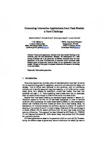
Figure 1: Generic Product Line Engineering Life Cycle To discern different product family members while having in mind the whole product family, decision models [3] are a commonly employed technique. The case-study Magrathea which is presented in this paper has been conducted at the Hasso-Plattner-Institute for Software Systems Engineering, Potsdam, Germany and is embedded in the context of the cooperative German research project PESOA (Process Family Engineering in Service-Oriented Applications, [4]). The PESOA project aims at taking software product lines to another level. While the classical product line approach is based mostly on static models during software design, PESOA also addresses dynamic aspects of software modeling (i.e. processes) that underlie software products. Thus, process variants throughout software product families form process families. In most cases, the concept of software product lines is combined with some approach to software generation. It is desirable to delegate the task of application implementation to machines rather than to humans to make software prod-
uct lines a really advantageous concept. This case-study focuses on software generation for process based software product lines and presents a complete tool chain that enables (a) domain developers (i.e. software developers) to define domain specific product line artifacts (i.e. domain engineering) and (b) product managers (or non-software developers in general) to configure concrete software products using process models and generate ready-to-run web applications in a simple and comprehensive way (i.e. application engineering). For the Magrathea case-study, a generic (i.e. non domainspecific) software generator framework and development methodology were conceived that can be employed to create process-based software generators for different application domains. Furthermore, this framework and methodology were applied to a concrete business case - namely hotel booking platforms - for evaluation purposes. This paper intends to present the Magrathea case-study and to familiarize the reader with the concepts and tools that build up the Magrathea software generators. It is structured as follows: Section 2 presents the software development methodology that users may follow to employ Magrathea for any business case. Section 3 gives an introduction on PESOA’s special view of software product lines, i.e. process families. It elucidates the concept of variability mechanisms as well as process building blocks. Section 4 deepens the theoretical foundation for pre-engineered and reusable development artifacts while section 5 outlines how the presented concepts were applied to a concrete business case. Section 6 presents the different tools that have been used and developed for Magrathea. Section 7 concludes on this work and mentions improvements and future research directions.
2.
mainly in straight-forward mapping of domain specific elements of the process family architecture model (i.e. building blocks) to code patterns (i.e. parameterized code templates, refer to Section 4). Subsequently, the generated generator (i.e. domain specific generator) is able to build every possible process variant comprised in the process family. The phase of domain engineering is completed with this last step. In application engineering, the analysis phase encompasses again scoping and determination of concrete application requirements. During application design, however, application engineers (i.e. business users or other non-software developers) can use ”Bauhaus” to derive a concrete process model from the process family (a) by resolving variation points in process family architecture models or (b) by freely combining process building blocks. The outcome of the application design phase is in both cases a concrete variant-free business process model. Using such a model instance (and some statical information as names or colors) as input for the above mentioned domain specific generator will produce a complete and ready-to-run web application which is based on the desired business process model. The complete application implementation phase is carried out by the generator.
3.
BUSINESS PROCESS FAMILIES
Most approaches to software product lines are based on features and feature-related decision models which seems obvious at first sight: A product line for a hotel booking platform could be described by a feature diagram noted in FODA (refer to [5]) like in figure 3. All main features are depicted as well as how they relate to each other. To configure a concrete application, an application engineer could take decisions for each option the model proposes.
DEVELOPMENT PROCESS
The Magrathea development process is aligned to the phases of the classical product line approach which are outlined in [2] and depicted in figure 1. Figure 2 illustrates the Magrathea development methodology, its components, artifacts and roles. It is best understood when read from left to right. Once a specific domain (e.g. hotel booking, book shopping, car rental, etc.) is determined and scoped (i.e. domain analysis), domain designers can use the ”Bauhaus Process Family Editor” to define a process family architecture model. This model comprises all possible process variants. It represents the outcome of the domain design phase. The modeling notation for process family architecture models is BPMN extended by variation points. Knowing the family architecture, the phase of domain implementation begins and domain developers can either (a) implement pluggable code artifacts to be mapped to process building blocks (read more on process building blocks in 3.1.4) or (b) implement concrete product family members (i.e. product variants) that are decomposed to code artifacts by pattern developers. Pattern developers will consequently use those code artifacts and the process family architecture model to configure the ”HyperSenses” 1 generator generator (i.e. a generator that generates a generator). This configuration step consists 1 HyperSensesTM is a trademark of Delta Software Technology
Figure 3: FODA Model of hotel booking platform variants. However and even though business processes are modeled as features in figure 3, it’s impossible to conclude the concrete business processes that underlie the different products (i.e. applications) that can be derived from this product family. Process models are used to describe those processes and various notations exist to express them in different manners. However, none of the existing notations take into account variabilities.
3.1
Variability Mechanisms
According to [6, p. 3] ”variability mechanisms denote techniques for the derivation of process model variants from existing process models” and their main purpose in terms of PESOA is to represent different processes (which all belong to the same process family) in one model. Figure 5 is an
Figure 2: Development Process example for a process model containing variability mechanisms. In [6] several variability mechanisms are presented as well as their application to different known process modeling notations. The Magrathea case-study employs the widely known Business Process Modeling Notation (BPMN, [7]). The main reason for a decision in favor of BPMN was our intention to allow business users without knowledge in software development to act as application engineers. BPMN was designed to be understood by this target group and is perceived as suitable for the Magrathea case-study by the authors. Consequently, the following paragraphs will outline the variability mechanisms that were employed in Magrathea and how they extend BPMN. Figure 5 in section 5 illustrates the application of variability mechanisms in BPMN.
3.1.1
Encapsulated Subprocesses
Subprocesses are a standard concept of BPMN [7] and most other modeling notations. They are referenced using a plus sign at the bottom of an activity node and modeled in detail in a separate pool. [6] gives an adequate analogy to explain encapsulated subprocesses by referring to components in component models. Assuming the principle of information hiding as perceived in [8], [9], [10] and transferring it to processes results in different subprocess instances which (a) are interchangeable, (b) can be invoked at the same point in a parent process and (c) have the same interfaces to the outer world (i.e. input and output data flow).
3.1.2
Abstract Subprocesses
In order to express an extension point [11], [3] in an extended BPMN diagram, the authors used abstract subprocesses [6] and an implements relation to denote possible implementations for a certain activity. See [6] for examples.
3.1.3
Null-Subprocesses
In order to allow subprocesses to be left out, abstract subprocesses can be implemented using a null-subprocess [6]. A null-subprocess does not execute any perceivable activity apart from handling through input data to following activities. In order to comply with their subprocess interface, null subprocesses potentially need to conduct data transforma-
tion or conversion.
3.1.4
Optional Stereotype
The optional stereotype [6] can be applied to a subprocess to express that it may but needs not to be present in a concrete process variant. If an optional subprocess is left out during derivation of process variants from process families, all sequence and data flows connecting to the optional subprocess must be left out as well. If sequence and data flows should not be removed but routed through upon omission of a subprocess, a conjunction of an abstract subprocesses and a null-subprocess must be used instead of the optional stereotype (see again [6]).
3.2
Process building blocks
Variability mechanisms offer a lot of flexibility to business process family modelers. However they lack the possibility of absolutely free recombination of process constituents. Process building blocks as conceived and employed in the Magrathea case-study propose a solution to this issue. Defining a business process for new product variant does not mean reinventing the wheel. In most cases, it solely consists in recombining existing basic activities to form a new way of executing work. Furthermore, we assume that the scoped application domain (e.g. car rental, on line shop, hotel booking) for a specific product line is limited. Therefore, already a repository of a limited number of basic domain-specific activities would enable a modeler to define sophisticated web applications belonging to his domain. Given a set of process building blocks (i.e. activities, gateways, data and control flow, subprocesses) defining the underlying process of a web application is a trivial task. We differentiate between domain-specific and general building blocks: Basic process activities are domain-specific, i.e. they belong to a well-defined domain of web application process steps (e.g. ”enter payment information”, ”book hotel”). Composed processes, control and data flow are considered to be general. A different application domain would not affect their interpretation. While defining patterns and code mappings for general building blocks was subject of the general work on Magrathea, defining code patterns for domain-specific building blocks is a task for software developers - not business users as outlined in 2. However, once a domain is covered by
building blocks, no more programming skills are needed. At this point, an important fact needs to be emphasized: Deriving concrete process models from process family models is out of the scope of the Magrathea case-study. For application engineers (i.e. business users) process family models provide a means to produce concrete business process models in a sophisticated way. Magrathea generators are designed to read those models - not process family models. Validation of process models against a process family model specification is part of future work on this topic (refer to 7).
4.
PROCESS MODELS AND DEVELOPMENT ARTIFACTS
Modeling a system always means depicting those system aspects that are relevant to a certain concern and leaving out others. While modeling every detail of the web application would disburden developers from writing code (like PSMs in MDA, [12]), it is non-trivial for business users. The abstraction level of all Magrathea models must be much higher. Simplicity of the models was prioritized above detailedness. The authors are aware of the fact that this prohibits direct model-to-code transformation (as in MDA), but the casestudy has proven that complete runnable applications can be generated, provided that domain-specific building blocks have been defined by developers beforehand.
4.1
Meta model
As mentioned before, business process models which act as input data for a Magrathea generator can either be derived from variant-rich process models in extended BPMN or be deliberately combined from process building blocks or both. Regardless of which way led to its definition, every Magrathea process model is based on the Magrathea meta model for business processes. The BPMN Specification [7] embraces a big set of elements which can be used to model business processes. However, to model Magrathea processes only a small extract of the BPMN set was used. The set of supported BPMN elements in Magrathea are as follows. A concrete web application can have various parallel processes embedded. All processes are modeled in a separate pool. A process can contain start events, end events, tasks, exclusive-or gateways and subprocesses connected by sequence flows. Figure 4 shows a simplified model of the meta model that was used in Magrathea to define processes. A modeled application directly contains all inlaid processes - whether they are top level processes or subprocesses. Embedded in the processes are the elements that define the control structure: tasks, gateways, events (only start and end events are implemented) and references to subprocesses. Sequence flows are contained by the process elements they start at and reference their targets. The main model elements are described below.
4.1.1
Pools (Processes)
In contrast to their main purpose as described in [7], the authors do not see pools as different participants in the process. The authors mainly rely on a pool’s definition as self-contained process as written in [13]. Furthermore, Magrathea introduces a hierarchy for processes: Processes (expressed using pools) can be included by other processes using the subprocess activity type. All top level processes (i.e. processes that are not referenced by a subprocess activity) are running concurrently2 .
4.1.2
Tasks
When referencing to tasks, one should have in mind the process building blocks that have been described in 3.1.4, i.e. single domain-specific process execution steps. Tasks 2
Concurrent processes can also be employed to offer users different options for interaction that are unrelated from a process point of view (e.g. language selection).
Figure 4: Simplified meta model of the Magrathea BPMN subset. can either be (a) User tasks or (b) Application tasks. In order to support user tasks, special application tasks have to precede and follow the main task and compose thus the activity. The usual case is data collection from the user which is done in web forms. Often, web forms require data that is available in the system beforehand. The collection of these data is done during a preparation phase. Then the actual web form is displayed to the user. Once the form is submitted, the application has to handle the received inputs. We call this the handle phase. The modeler would not care about those phases as they are not part of the business process. Thus, they don’t have to be modeled. An activity which represents a user task is modeled as one BPMN activity node. Application tasks which are not implicit (i.e. linked to a user task as prepare or handle) have a semantic relevant to the business process. For instance, ”search hotels via web service” or ”save data to database” are application tasks. The modeler understands their meaning however he does not care about their implementation. They are modeled as single BPMN activity nodes as well.
4.1.3
Subprocesses
A subprocess node refers to one of the above mentioned processes and includes its functionality. This modeling technique can be used to simplify diagrams or to reuse model elements in several different places.
4.1.4
Start and End Events
Start and end events spot the start and end points of a process respectively. These are considerably important for code generation. Refer to 4. At the time of this writing, the authors did not consider triggers and results nor scope events.
4.1.5
Gateways
Gateways route the control flow of a process. The semantic of the gateways that are to be employed in Magrathea models is exclusive or. Outgoing sequence flows must have conditions that are to be evaluated at run-time.
4.1.6
Sequence Flow
Sequence flow links sequence nodes (i.e. activities, gateways) to each other and defines their execution order. A sequence flow must have a condition in case it flows from a gateway.
4.1.7
Data Objects
A data object represents a well-defined data package that is to be passed from one task to another (i.e. is the output from a task and the required input to a task). Data objects can be connected to activities using message flow (see below). If a data object has an outgoing flow to an activity it must have an incoming flow from another activity, elsewise the model is not valid.
4.1.8
Message Flow
Message flow links activities and data objects. The modeler can express the flow of in- and outputs using message flow.
4.2
Model-based Code Generation
The HyperSenses generator generator which is used in Magrathea has been conceived and developed by Delta Software Technology, a member of the PESOA project and a technology partner for this case-study [14]. It is model-based, and can be configured using MOF style meta models [15], [16]. Once configured with the Magrathea meta model, the user can define code pattern hierarchies. Starting with a given class of the meta model (i.e. Application in Magrathea) each code pattern is bound to a meta model class [17]. A subordinate (i.e. child) code pattern can be included in any pattern and must thus be bound to another meta model class which is embedded or referenced by the class the current pattern is bound to. Thus, a complete model instance (i.e. a business process model) can be processed by HyperSenses and code patterns will be stringed together according to their meta model related definition in the above mentioned step. Furthermore, patterns can have slots and blocks. Both are referencing to features of the meta model class that the pattern is bound to. Slots simply use feature values of con-
crete model instances during code generation to put them into the generated code. Blocks however, can be used to include or skip code blocks which are defined in a code pattern according to true or false evaluation results of expressions accessing feature values of the model instance.
Listing 2: User actions def TASK_NAME PREPARE_BLOCK render " TASK_NAME " end
4.3
def handle_TASK_NAME HANDLE_BLOCK PATTERN_REF end
Code Patterns
A Magrathea generator as outlined in 2 must be able to produce domain specific and general code. Domain specific code reflects the domain specific building blocks and is composed using domain specific code artifacts. Generic code must be produced for all kinds of control flow and subprocess embedding facilities. Both is done in HyperSenses. However, this section covers generic code. How domain specific code must be incorporated into patterns is described in 5. The Magrathea case study was conducted using the Ruby on Rails web application framework [18], [19] which is based on the commonly known ”Model View Controller” (MVC, [20]) design pattern. Hence, the programming paradigm is aligned to MVC and code examples are in Ruby programming language [21], [22].
4.3.1
Processes and Controllers
As described in 4.1.1, Pools are self-contained processes and form a semantically coherent entity as well. Thus, pools are mapped to controllers following the MVC paradigm. For each pool that is contained in the process model, a new controller is generated by Magrathea which consists basically in the following lines of code: Listing 1: Controllers class P O O L_ N A M EC o n tr o l l er < ApplicationController PATTERN_REF_1 def leave_controller ( params ) PATTERN_REF_2 redirect_to params end end Where POOL_NAME is a slot referencing the name of the current pool class and PATTERN_REF_1 references the subpattern that is bound to the task feature of the pool class3 . Read 4.3.2 to understand this pattern. PATTERN_REF_2 references a subpattern which is explained in the context of end events in 4.3.7.
4.3.2
Tasks and Actions
A task as mentioned in 4.1.2 can be (a) a user task or (b) an application task. In case (a) it is mapped to two controller actions and a view following MVC. This is: First, a preparation phase in which data is collected and prepared for output to the user and a specific view is called. Second, a handle phase, during which data inputs from the user are collected, prepared and potentially checked or stored. For case (a) a code frame like in listing 2 is generated: 3
Where TASK_NAME is again a slot referencing the name of that task. Both, PREPARE_BLOCK and HANDLE_BLOCK, are blocks as described in 4.2. have to be substituted by a number of domain-specific code lines (i.e. building block code artifacts, refer to 5). The render statement is used in Ruby on Rails to render an HTML view. HTML views are separate files in Ruby on Rails. Their development falls into domain implementation as well. PATTERN_REF references the subpattern which is bound to the embedded outgoing sequence flow feature of this task class. Case (b) however, is much simpler:
The task feature has a cardinality of zero to many. Consequently this subpattern is expanded for every referenced task instance.
Listing 3: Application actions def TASK_NAME BLOCK PATTERN_REF end Here, BLOCK has to be substituted by domain-specific code performing the application action.
4.3.3
Subprocesses and redirects
The code pattern for a subprocess solely references a subpattern which is bound to the process feature of the subprocess class. This subpattern, however, renders the code which is shown in listing 4. Listing 4: Subprocess @params [: action ] = : index @params [: controller ] = PROCESS_NAME redirect_to @params In listing 4 PROCESS_NAME is a slot reference to the name feature of the process class. As processes map directly to controllers, the three code lines above redirect the user’s browser to the index action of the controller that maps to the referenced process. See 4.3.4 to understand index actions and how they map to start events.
4.3.4
Start events and index actions
Each process must have a start event. The code that is produced whenever a start event class instance is encountered is as follows: Listing 5: Start Event def index PATTERN_REF end The PATTERN_REF references a subpattern which is bound to the outgoing sequence flow feature of the start event class. See 4.3.5 to understand how sequence flow generation works.
4.3.5
Sequence Flow
The sequence flow pattern which is bound to the sequence flow class solely references four more subpatterns. Depending on which class is referenced by the feature of the sequence flow class, one of them is expanded. If it is a gateway, the gateway pattern is expanded, read 4.3.6. If it is a task, the the pattern shown in listing 6 is expanded. Listing 6: Sequence flow to an action TASK_NAME TASK_NAME is a slot which references the name feature of that task. As activities are directly mapped to controller actions, the simple statement of its name would call the defined action in Ruby which is the desired behavior. If it is a subprocess, the subprocess pattern is expanded, read 4.3.3. If it is an end event, the end event pattern is expanded, read 4.3.7.
4.3.6
Gateways
The gateway pattern is bound to the gateway class which can be referenced to by a sequence flow class feature. As gateway class instance features also reference sequence flow class instances, the case-when statement in listing 7 in conjunction with listing 8 renders the desired application behavior.
Listing 9: End event leave_controller The statement leave_controlleer calls a method that is defined for every controller in 4.3.1. The pattern reference PATTERN_REF_2 in this pattern references a subpattern construct that determines whether the current process is toplevel and if not, where the outgoing sequence flow instances of the embedding subprocess class instance point at to determine the continuation of sequence flow.
5.
A CONCRETE APPLICATION DOMAIN
As outlined before, the Magrathea case-study comprised both the development of the generator framework described before and its evaluation on the basis of a concrete business case: hotel booking platforms. Domain analysis produced several different requirements that both operating companies and users had regarding hotel booking platforms. The following list lines out those, that are reflected in processes. • Basic requirements – Search for hotels – Display search results – Display hotel details – Display different pricing categories – Enable user to enter personal details – Enable user to enter payment information
Listing 7: Gateway case case true PATTERN_REF end PATTERN_REF references a subpattern which is bound to the feature referencing the sequence flow class4 . This subpattern is shown in listing 8. Listing 8: Gateway when when ( S E Q U E N C E _ F L O W _ C O N D I T I O N ) PATTERN_REF_1 PATTERN_REF_2 PATTERN_REF_3 PATTERN_REF_4 end SEQUENCE_FLOW_CONDITION is a slot which is bound to the condition feature of a sequence flow (see 4.1.6). Thus, the generator inserts the right condition expressions before expanding further patterns. These conditions are evaluated at application run time. The Pattern references PATTERN_REF1 to PATTERN_REF4 are the same as those described in 4.3.5.
– Enable user to commit a booking request • Advanced requirements – Allow user to register and log in – Provide single-sign-on, disable registration5 – Enable user to store and change a personal profile – Prefill personal and payment detail fields for logged in user – Display past bookings – Enable user to cancel a booking – Enable user to book a visited hotel again – Deny booking for non-authorized user – Skip personal and payment information forms for logged in user5 – Display text messages in different languages
The end event pattern is bound to the end event class which can be referenced to by a sequence flow class feature. The produced code line of the end event pattern is as simple as shown in listing 9.
During domain design, a variant-rich process model has been developed which represents the process family architecture for the hotel booking platform domain. Figure 5 depicts the process family architecture in an extended BPMN notation. Note, that most of the product variants from figure 3 are reflected through variability mechanisms in figure 5. Domain implementation comprised the development of (a) controller code blocks that collect data from models and prepare it for the views, (b) views that display data to the user and potentially collect data in web forms (c) controller code blocks that validate, manipulate data and interact with
4 The outgoing sequence flow feature of the gateway class has a cardinality of one to many.
5 The use case here is corporate booking for business trips on intranet booking portals.
4.3.7
End events
Figure 5: Process family for hotel booking platforms.
models to store them and (d) models that handle persistence of data and interact with a third-party web service to collect hotel information and commit bookings. Obviously, in most cases controller code was structured and organized into code patterns as controllers implement the control flow of a MVC based web application. However, view and model code needed to be split up and enriched by slots and blocks (refer to section 4.2) as well in order to support hyperlinks, persistence and other elements that are bound to specific product variants. The resulting generator for hotel booking platforms has been used, tested6 and presented to different partners of the PESOA project.
6.
MAGRATHEA TOOL CHAIN
Figure 2 from section 2 gives a hint on the machinery that is behind Magrathea’s code generation. The tools that the authors used to carry out this case-study are presented in the following sections.
6.1
Delta HyperSenses
HyperSenses is a generator technology [25]. It is implemented in two different tools that have been used for Magrathea. HyperSenses Meta Composer can be perceived as an IDE for software generators. The authors used Meta Composer to develop the Magrathea meta model, the pattern hierarchy and the code artifacts to be mapped on process building blocks. The generated generators can be executed using HyperSenses Active Intent which was developed to support featurebased generator configuration but can also be solely employed to run the Magrathea generator by business users. HyperSenses is currently developed at Delta Software Technology, Schmallenberg, Germany and was extended to import Bauhaus XMI process models during the Magrathea case-study [26].
6.3
7.
Ruby on Rails
Ruby on Rails is not a tool. It is a development framework for web applications which is based on the Ruby programming language. The Magrathea team developed all of the target domain code artifacts in Ruby on Rails. Ruby on Rails can be developed using any text editor. Rails comes with a lightweight application server to run Rails applications on during development. 6 Integration tests were carried out manually. Automated testing of generated code is out of scope of this case-study.
CONCLUSION AND FUTURE WORK
Both, the conceptual foundation and the generator framework that were presented in this paper have proven usable and helpful for the investigated application domain. The authors believe that their application to other domains will be considerably beneficial for cases in which a large number of similar but different web applications need to be developed and overlooked. Future work on Magrathea that shall be carried out at Hasso-Plattner-Institute and in the context of PESOA may include: • A graphical editor that supports extended BPMN models with variability mechanisms and derivation of process variants from family architecture models.
Bauhaus
Bauhaus is a modeling tool which is based on the commonly known Eclipse platform. At the time of this writing it supports graphical editing of generic BPMN models with support for domains and domain-specific process building blocks. In-memory Models of BPMN models are managed as EMF [23] data structures and may be exported to XMI [24]. The Bauhaus development is led by Hagen Overdick, PhD. student at Hasso-Plattner-Institute, Potsdam, Germany. Future work on Bauhaus includes support for extended BPMN models with variability mechanisms and derivation of concrete process variants from process families.
6.2
Ruby on Rails is a community project whose main actor is David Heinemeier Hansson. It is still under development but has reached a very stable and sophisticated state by the time of this writing.
• Automatic validation of process models against a process family architecture for case (a) of section 2. • Implementation of pre and post conditions for process building blocks and automatic validation for case (b) of section 2. • Generic code patterns for BPMN data objects and data flow • Interaction of more than one user party and collaborative processes
8.
RELATED WORK
Big parts of the conceptual framework behind Magrathea have been elaborated by the PESOA project which focuses on software product lines but addresses mainly dynamic aspects, i.e. processes, which have not been investigated in this context before. Remarkably, the AndroMDA [27] open source MDA generator also proposes a so-called cartridge that is able to generate very sophisticated Java Struts web applications from UML Activity Diagrams. It is called Bpm4Struts [28]. However, Bpm4Struts expects input models with a much higher detailedness. The authors believe that business users - who are targeted as application engineers by Magrathea - would be overextended when asked to use AndroMDA. Furthermore, AndroMDA does not address the concept of software product lines at all. In [29] the authors introduce the Object-Oriented Hypermedia Design Model (OOHDM). It splits the development of hypermedia web applications into different activities, namely conceptual design, navigational design, abstract interface design and implementation, which are each supported by - mostly object-oriented - modeling formalisms, the OOHDM notation. An existing CASE environment eases the modeling in the OOHDM notation and generates code templates out of those models. The framework OONavigator can be used to provide easy access to the information space of object-oriented applications enriching the application by hypertext features. The Web Modeling Language (WebML) is a visual notation which provides the modeling of data-intensive web
applications mainly from the three perspectives data, hypertext and presentation model. [30] suggests to first define the business processes underlying the desired web applications and to generate WebML hypertext skeletons implementing their behavior. After refining the generated models running web applications can be generated or implemented. In contrast the PESOA approach skips this step of refining the models as this was already accomplished during the domain engineering phase. The Web Site Design Method (WSDM) is a approach to model web applications with a strong focus on the user groups. The modeling of the audience precedes the phases of the conceptional design and the implementation design. Running web applications can be generated automatically using a transformation pipeline once all the modeling phases have been completed. [31] provides an overview about the generation step of WSDM. As detailed information about the desired web application is required for generation, modeling is exclusively done by software developers as opposed to the Magrathea case study, where the underlying business processes can be described by non-IT domain experts.
9.
ACKNOWLEDGMENTS
The Magrathea case study was carried out by Orlando D¨ ohring, Silvan Golega, Wieland Lindenthal, Olaf M¨ arker, Lukas Neitsch, Gregor Schmidt and Jan Schulz-Hofen It was appreciatively supported by Mathias Weske, Martin von L¨ owis, Hagen Overdick and Arnd Schnieders
10.
REFERENCES
[1] Patrick Donohoe, editor. Software Product Lines Experience and Research Direction, Denver, Colorado, USA, August 2000. [2] Dirk Muthig Joachim Bayer, Stefan Kettemann. Principles of Software Product Lines and Process Variants. Technical Report 4, PESOA, February 2004. [3] P. Clemens and L. Northrop. Software Product Lines: Practices and Pattterns. Addison-Wesley, 2002. [4] Mathias Weske. Pesoa: Process Family Engineering in Service Oriented Applications. In Er¨ offnungskonferenz Forschungsoffensive ”Software Engineering 2006”. Hasso-Plattner-Institut, July 2004. [5] Krzysztof Czarnecki and Ulrich W. Eisenecker. Generative Programming. Addison-Wesley, 2000. [6] Jens Weiland, Mathias Weske, Frank Puhlmann, Arnd Schnieders. Process Family Engineering Variability Mechanisms. Technical Report 17, PESOA, June 2005. [7] Object Management Group. Business Process Modeling Notation Specification, February 2006. [8] D. Webber H. Gomaa. Modeling Adaptive and Evolvable Software Product Lines using the Variation Point Model. In Proceedings of the 37th Annual Hawaii International Conference on System Sciences, HICSS’04, pages 1–10. IEEE, IEEE Computer Society Press, January 2004. [9] H. Gomaa. Designing Software Product Lines with UML: From Use Cases to Pattern-Based Software Architectures. Addison-Wesley, 2005. [10] M. Syahnberg, J. van Gurp, J. Bosch. On the Notation of Variability in Software Product Lines. In Proceedings of WICSA 2001, August 2001.
[11] Jan Bosch. Design and Use of Software Architectures: Adopting and Evolving a Product-Line Approach. Addison-Wesley, May 2000. [12] J. Miller, J. Mukerji. MDA guide version 1.0.1. Technical Report, OMG, June 2003. [13] Stephen A. White. Introduction to BPMN. IBM, May 2004. [14] Winfried Buhl, Cord Giese. Sofware-Generatoren. Technical Report 4, PESOA, February 2004. [15] OMG. Meta Object Facility (MOF) Core Specification, January 2006. [16] W. Buhl, C. Giese. Modell-basierte Prozesstransformationen. Technical Report 10, PESOA, October 2004. [17] R. Schilling, C. Giese. Modellgetriebene Generatorenentwicklung. OBJEKTspektrum, March 2005. [18] David Heinemeier Hansson. Ruby on Rails: Web Development that doesn’t hurt. http://www.rubyonrails.org [19] D. H. Hansson D. Thomas. Agile Web Development with Rails. The Pragmatic Programmers LLC., 2005. [20] Trygve Reenskaug. Models - Views - Controllers, 1979. http://heim.ifi.uio.no/ trygver/1979/mvc-2/1979-12MVC.pdf [21] Ruby: Programmers’ best Friend. http://www.rubyonrails.org [22] Dave Thomas. Programming Ruby. The Pragmatic Programmers LLC., 2nd edition, 2005. [23] E. Merks, R. Ellersick, T. J. Grose, F. Budinsky, D. Steinberg. Eclipse Modeling Framework. Addison-Wesley, 1 edition, August 2003. [24] OMG. MOF 2.0 / XMI Mapping Specification, V2.1, September 2005. [25] Delta Software Technology GmbH. HyperSenses Tutorial. HTML online help, October 2005. http://www.d-s-t-g.com/HS [26] H. Overdick, W. Buhl, C. Giese. Realisierungsstrategien f¨ ur Prozessfamilien. Technical Report 15, PESOA, 2005. [27] Joel Kozikowski. A Bird’s Eye View of AndroMDA. AndroMDA. http://galaxy.andromda.org/docs3.1/contrib/birds-eye-view.html [28] AndroMDA Team. AndroMDA BPM4Struts Cartridge v.3.2-RC1-SNAPSHOT Project Documentation, 2006. [29] Daniel Schwabe, Gustavo Rossi. An Object Oriented Approach to Web-based Application Design. Technical Report, Departamento de Inform´ atica. PUC-RIO, Brazil and LIFIA, Fac Cs. Exactas, UNLP, Argentina; CONICET; UNLM. [30] Marco Brambilla. Generation of WebML Web Application Models from Business Process Specifications. Technical Report, Politecnico di Milano, Dipartimento di Elettronica e Informazione. [31] Peter Plessers, Sven Casteleyn, Yeliz Yesilada, Olga De Troyer, Robert Stevens, Simon Harper, and Carole Goble. Accessibility: A Web Engineering Approach. Technical Report, Vrije Universiteit Brussel and School of Computer Science at the University of Manchester, 2005.