int. j. geographical information science, 2002 vol. 16, no. 8, 713–748
Research Article Generic query tool for spatio-temporal data PETER VAN OOSTEROM†, BART MAESSEN‡ and WILKO QUAK† †Department of GIS Technology, Faculty of Civil Engineering and Geosciences, Delft University of Technology, P.O. Box 5030, 2600 GA, The Netherlands ‡Cadastre Netherlands, P.O. Box 9046, 7300 GH Apeldoorn, The Netherlands; e-mail:
[email protected],
[email protected],
[email protected] (Received 3 March 2001; accepted 21 September 2001) Abstract. Geographical information systems are more and more based on a DBMS with spatial extensions, which is also the case for the system described in this paper. The design and implementation of a generic geographical query tool, a platform for querying multiple spatio-temporal data sets and associated thematic data, is presented. The system is designed to be generic, that is without one speci c application in mind. It supports ad-hoc queries covering both the spatial and the thematic part of the data. The generic geographic query tool will be illustrated with spatial and thematic Cadastral data. Special attention will be given to the temporal aspects: a spatio-temporal data model will be described together with a set of views for easy querying. DBMS views play an important role in the architecture of the system: integration of models, aggregation of information, presentation of temporal data, and so on. The current production version of the geographic query tool within the Dutch Cadastre is based on GeoICT products with a relatively small market share (Ingres and GEO++). A new prototype version is being developed using mainstream Geo-ICT products (Oracle and MapInfo). First results and open issues with respect to this prototype are presented.
1.
Introduction Traditionally, most Geographical Information Systems (GIS) can only query and display information that is under the control of the speci c system (e.g. stored in a proprietary le format). Spatial data that are created and managed outside a speci c GIS cannot be queried in this GIS. Since more and more spatial functionality is available within DBMSs (Database Management Systems, outside a GIS), a more generic GIS approach is required, which can work with spatial data in a model not controlled by the GIS. In this paper a tool based on a generic GIS using a DBMS is described. When trying to design a generic information system, one is rst confronted with the fundamental question: is it possible at all to develop an information system without a speci c application (data and functionality) in mind? It could be argued that it is impossible because it is not known which data sets are needed, which Internationa l Journal of Geographical Information Science ISSN 1365-8816 print/ISSN 1362-308 7 online © 2002 Taylor & Francis Ltd http://www.tandf.co.uk/journals DOI: 10.1080/13658810210149399
714
P. van Oosterom et al.
functions are needed, what the user interface should look like, and so on. However, the system presented in this paper is an attempt to develop such a generic system. Of course, the application domain of the system is not unlimited and could be characterized as a geographical query tool. It should be noted that even this focus is not strictly needed. The tool could also be used for non-geographica l data and for data entry or manipulation. Once loaded with (diVerent) data sets, the system could be described as a spatial data warehouse. In this paper the term geographical query tool is preferred. The usefulness of the generic geographical query tool is tested in practice. The integration of multiple geographical data sets and associated thematic ( legal) data in one DBMS is described within the context of the Dutch Cadastre. The data set is nationwide and available for analysing and performing consistency checks on the Cadastral data. The purpose is to create an environment with easy access to all the data. Therefore a user-friendly interface is needed on top of this DBMS. The Dutch Cadastre has the advantage over most other cadastral organisations that it maintains both the cadastral map and the (administrative legal/tax) registers unlike many other countries where these registrations are the responsibility of di Verent organizations; e.g. in Italy (Arcieri et al. 1999) or France (Spe´ry et al. 2001 ). Section 2 gives an overview of the generic geographical query tool system architecture. The system architecture of a generic geographical query tool is based on two components: the backend, a spatial DBMS, and the frontend, a (geo)graphical user interface for comfortable query formulation and showing the results. The frontend is generic in two ways. First, it supports any data model. Second, it uses the (spatial) functionality oVered by the DBMS. The backend is generic in the sense that it should be able to handle the formulated queries eYciently. That is, the backend should have a good query optimizer taking into account both spatial and thematic aspects of the query. Section 3 introduces the basic Cadastral data models for the geometric and administrative data in our case study with emphasis on the temporal aspects of the geometric model. In traditional (non-spatial) information systems users interact with data by specifying a key, such as an identi cation number. An alternative is browsing or viewing large tables of information which are ordered; e.g. alphabetically. Using administrative and geometric data in an integrated manner gives a new entrance: the map. In the DBMS of the generic geographical query tool, the original data models (base tables) are not changed. However, DBMS views are used to present the data in a more appropriate manner: integrated, aggregated, time speci c and with cartographic attributes; see §4. Speci c add-ons to the basic components of the generic architecture, extensible relational DBMS and generic GIS-frontend, are described in §5. The custom made add-ons are used for: easier access to data: select just one function, instead of querying several tables; analysis not possible in a relational DBMS: e.g. intersection of a topologically structured area feature with a polyline; and introduction of new interface concepts: e.g. the ‘active set’. The usefulness of the tool is shown by a number of quite di Verent cases from the real world, each illustrating diVerent aspects of the system. These applications are based, among others, on the following generic concepts: spatial aggregates, historic spatial data, spatial join, integrated geometric and thematic data, SQL and shell scripts. A number of practical use cases are described in §6 with emphasis on temporal applications. Section 7 shows the rst results of the recent investigations within the Dutch Cadastre to migrate the query tool environment towards mainstream Geo-ICT solutions,
Generic geographical query tool
715
summarizing the obtained results and the remaining open issues. The paper concludes with a short list of other practical uses and future developments in §8. In summary, the generic geographical query tool can be used for easy querying, analysis and visualisation of any geographical and related thematic data needed during solving many types of diVerent tasks. 2.
System architecture This section gives an overview of the architecture of the generic geographical query tool. First, some remarks with respect to developing generic (DBMS-based) information systems in general are made in §2.1. The geographical query tool system is based on the backend Ingres DBMS (ASK-OpenIngres 1994, van Oosterom 1997) and the frontend GEO++ GIS package (Professional Geo Systems (PGS) 1996, Vijlbrief and van Oosterom 1992). The DBMS backend will be described in §2.2 and the GIS frontend is described in §2.3. 2.1. Generic information systems Designing and developing a generic information system, such as the query tool, is not trivial and requires speci c techniques. The implementation cannot use hardcoded names of objects (tables), attributes, operators, etc. The foundation of most information systems is a DBMS (in contrast to traditional GIS, which are le based) and this is also the case for the generic geographic query tool. The DBMS-based architecture also gives the rst indications of how to develop a generic application. One of the goals of the language SQL itself is to separate the high-level functionality (what is requested by the user) from the implementation (how is this obtained ). Further, the current data model managed by the DBMS can be obtained by querying system catalogues with meta data; below the example in Ingres (meta data in system catalogue iicolumns) and Oracle (meta data in system catalogue ALL_TAB_COLUMNS ) to obtain the data model. Note that these queries have to return the description of both (real ) tables and views. Further note that though SQL itself is standardized, obtaining the same information from the system catalogues diVers between DBMSs. /* Ingres example */ SELECT table_owner, table_name, column_sequence, column_name, column_internal_datatype, column_internal_length, column_internal_ingtype FROM iicolumns ORDER BY table_owner, table_name, column_sequence /* Oracle example */ SELECT OWNER, TABLE_NAME, COLUMN_ID, COLUMN_NAME, DATA_TYPE, DATA_LENGTH FROM ALL_TAB_COLUMNS ORDER BY OWNER, TABLE_NAME, COLUMN_ID
The generic geographical query tool uses this information, that is, the names of the tables and the names and data types of attributes, in the interaction with the user. Note that a data type can be a geometric data type. The way geometric data types are managed by the DBMS can be either by speci c data types such as point, polyline and polygon or by one generic geometric type (which can internally represent any number and combination of basic types, such as points, lines, and polygons) .
716
P. van Oosterom et al.
The advantage of speci c data types is that they allow the designer of the data model to specify more accurately the geometric type of the attribute of the feature in the real world. The advantage of the generic geometric type is that it is closed under the intersection operation: e.g. the intersection of two generic geometric types is always a generic geometry type. This is not true for the speci c geometric data types such as a polygon: the intersection of two polygons can be a collection of points, polylines and polygons. Note that this closure property is nice, but there are other wellaccepted data types that are also not closed under certain operations; e.g. integer under division: 1 divided by 2 is 0.5 and not an integer. Another advantage of speci c geometric data types is that the generic geographical query tool can present the user with visualization options suitable for a speci c type: e.g. cartographic symbolization for a point, line style and width for a polyline, ll pattern for a polygon, etc. It is possible to think of a, less obvious, solution to present visualization options for the generic geometric type. The OpenGIS consortium has chosen in its simple feature speci cation standard SFS/SQL (Buehler and McKee 1998, Open GIS Consortium, Inc. 1999) for speci c geometric types. There are several DBMSs available implementing these speci c geometric types and functions; e.g. Informix (2000) or IBM DB2 (2000). Oracle has chosen the generic geometric type approach (internally inspired by the OpenGIS SFS model). The Ingres geometry implementation dates back several years before the OpenGIS SFS/SQL standard, but is also based on speci c geometric data types within OME/ SOL (Object Management Extension/Spatial Object Library) (ASK-OpenIngres 1994, van Oosterom 1997). All modern (object) relational DBMSs can be extended with new (spatial ) data types and functions/operators. Therefore the frontend cannot assume a xed number of functions oVered by the DBMS. Similarly to obtaining the data model from system catalogues (meta data), it is possible to obtain information about the available data types and operators from the system catalogues. For an operator this information consists of at least the name of the operator, the number of operands, the data types of the operands and the data type of the return value. This information is used by the generic geographical query tool to assist the user in the formulation of correct queries based on the operations oVered by the DBMS. Note that there is no real diVerence between spatial and non-spatial data types with respect to this generic functional approach. 2.2. DBMS backend Besides the ‘standard’ DBMS functionality, the DBMS should also give access to the description of the current data model and available data types and operators; see §2.1. Unfortunately in the previous subsection it became clear that this part of the DBMS is less standardized than the query language SQL. DiVerent DBMS vendors have chosen di Verent solutions, that is, they oVer diVerent system catalogues. This makes porting the generic geographical query tool from one DBMS to another more diYcult than just linking the query tool system code with a diVerent DBMS interface library. The geographical query tool DBMS has a data warehouse nature. Periodically large amounts of data are copied into the query tool DBMS, creating a huge data set. The advantage of having all data integrated in one DBMS should not be countered by degraded interactive response times. In the generic geographical query tool, DBMS performance on a large data set should be virtually the same as in a
Generic geographical query tool
717
DBMS containing only a small data set. This can be achieved by applying proper (spatial) data clustering and indexing techniques. Also integrated (geometric and administrative ) views using data from diVerent tables must be at the same speed as pure geometric views; e.g. when using some administrative information from a related table to colour code a geometric entry on the map. The same holds for the temporal or historic views, an historic map or change over a period must be at the same speed as retrieving and displaying current date/time. The key entries to the generic geographical query tool DBMS are in general a region (usually a rectangle, sometimes just one point), or an administrative identi er; e.g. parcel number, address or owner name. Whenever possible data are organised based on spatial location, because a typical map contains thousands of objects and it would be ineYcient to retrieve them from diVerent physical locations on disk. This is obvious for the geometric data; for example by using the spatial location code SLC (van Oosterom and Vijlbrief 1996). However, this is also applied to administrative data which can be linked in one way or another to spatial data; e.g. the owners of a parcel could be clustered by postal code of their residence. This enables spatial range queries to perform well in all situations including the integrated geometricadministrative views. The other entries are supported by secondary indices ( b-tree (Comer 1979) or r-tree (Guttman 1984)), because they usually return one or a few results. 2.3. GIS frontend One important requirement is that the generic geographic query tool must be open, i.e. it may not be based on a GIS vendor speci c data format. This is a similar motivation as the one driving the OpenGIS consortium (Buehler and McKee 1998, Open GIS Consortium, Inc. 1999). However, the generic geographical query tool developments within the Cadastre started about seven years ago, before the OpenGIS standards and products were available. However, it is based on the same principle and it is expected that migration to OpenGIS products should not be too diYcult (§7). At this moment, many GISs still do not support this open DBMS approach. The traditional approach is that geometric data have to be stored in the GIS vendorspeci c format. Quite often, GIS have the capability to access an external DBMS. Usually this means that the geometric information still has to be stored locally, but with the help of a key, the corresponding administrative data can be found in the external DBMS. This is not good enough, since complete integration of geometric and administrative data is the most eYcient and consistent data management architecture. A generic geographical query tool must function as a frontend to the DBMS backend. The generic geographical query tool assists the user in posing questions through a user friendly interface. The generic geographical query tool generates ANSI SQL dynamically and processes the responses of the DBMS. GEO++ is a GIS which is designed to deal with this. Therefore, GEO++ can be described as a generic query tool for relational DBMS with spatial extensions. 3.
Cadastral data The generic geographical query tool will be illustrated with examples from a Cadastral system. To understand these examples, this section introduces the data model of the Cadastre in The Netherlands. The geographical data sets consist of large-scale topographic data and the cadastral maps of all the provinces in The Netherlands. Associated with the cadastral maps are administrative data, which
718
P. van Oosterom et al.
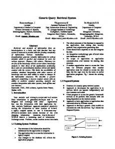
are also organised per province, but stored in a central mainframe. The relationships between the parcels on the cadastral map and the administrative data are through the nationwide unique parcel numbers. The cadastral maps are based on a topologically structured model and manipulating area features in such a model involves navigation using the topology references to the boundaries. It is interesting to note that the topology speeds up the visualization compared to a representation without topology, because in the latter case all coordinates are transferred twice from DBMS to the application: once for the polygonal face on the left side and once for the polygonal face on the right side. The topographic maps and the cadastral maps contain the full history since their introduction in 1997. This is not (yet) the case for the administrative data. Currently, the large-scale topographic and cadastral data are maintained by the LKI system (L andmeetkundig Kartogra sch Informatiesyteem (in Dutch): Information System for Surveying and Mapping), which stores the data in an Ingres DBMS using OME/SOL (Object Management Extension/Spatial Object Library) (ASK-OpenIngres 1994, van Oosterom 1997). Legal and other administrative data related to parcels are maintained by the AKR system (Automatisering Kadastrale Registratie (in Dutch): Automated Cadastral Registration), which stores the data in an IDMS DBMS on an IBM mainframe. This data set will be referred to as the administrative data in contrast to the geometric data. The generic geographical query tool has its own DBMS, which contains a copy of all geometric and administrative data in their original data models. Therefore, a good understanding of the two data models, as a case study, is important. These data models contain structures, which can be found in many other applications; e.g. metric, topology and measurement information (date, accuracy, type of measurement ) within the geometric data and hierarchies, n-to-m relationships, generalization/ specialization structures within the administrative data. These structures and their semantics are relatively diYcult to deal with in a generic geographical query tool environment. However, they have to be included in a generic geographic query tool which is acceptable for users familiar with this model. In §3.1, the geometric model of the Cadastre will be described in more detail. Followed by a description of the administrative (legal) model in the next subsection. The last subsection gives some numbers indicating the size of the query tool data set. Also, the load process of the data into the query tool DBMS is described. 3.1. Geometric model Since 1997 the geometric DBMS keeps track of all geometry changes over time, that is, it contains a spatio-temporal data set. The geometric attributes of type point, polyline and box are stored in the relational DBMS together with the other attributes describing the measurement (data, accuracy, etc.). The geometric data model for the cadastral parcel layer is based on wingededge topology (Baumgart 1975) as described in (Lemmen and van Oosterom 1995, van Oosterom 1997, van Oosterom and Lemmen 2001); references in this topology model are visualized in gure 1. In addition to the topologically structured cadastral parcel layer, this model also includes topographic layers, which are not (yet) topologically structured. Though some operations in a relational DBMS are impossible on a topologically structured area feature (e.g. compute area), this structure has many advantages:
Generic geographical query tool
Figure 1. E
E
E
E
719
The topology references in the winged-edge structure of the geometric model.
It avoids redundant storage of shared edges and vertices in a planar partition of space (and therefore is more compact than a full-polygon model). It is more eYcient during the visualization of the data stored in the DBMS in some kinds of front-end, because less data has to be read from disk and transferred to the front-end. It is the natural data model for certain application; e.g. during surveying an edge is collected (together with non-geometric attributes belonging to a boundary) and not a polygon. The topology structure can be used eYciently in certain operations (e.g. nd neighbour).
The next paragraphs elaborate the temporal aspects in the geometric model. First, the temporal model itself will be introduced, then some temporal examples will be given, and nally some open questions will be discussed. 3.1.1. Spatio-temporal model In the last decade quite a lot of attention has been paid to methods of modelling, storing, indexing (clustering), editing (updating) , manipulating, analysing, and visualizing, spatio-tempora l data. Books or literature papers concentrate on one or more of these aspects. Good overviews of handling spatio-temporal data can be found in (Langran 1992, Al-Taha et al. 1994, Abraham and Roddick 1999, CHOROCHRONOS: A Research Network for Spatiotemporal Database Systems 1996–2000). Some papers emphasise modelling (Tryfona and Jensen 1999, Worboys 1994), some emphasise functionality or analysis (Peuquet and Wentz 1994, Raafat et al. 1994, Erwig et al. 1999, Kollios et al. 1999, Hornsby and Egenhofer 1998) and some access methods (Relly et al. 1999, Nascimento et al. 1999). Some papers speci cally focus on temporal aspects in the cadastral domain: such as access and update in a distributed environment (Arcieri et al. 1999), model predecessor-successor relationships (Spe´ry et al. 2001), or event-based modelling (Chen and Jiang 1998). The updates in the spatial database of the Cadastre are related to changes of a discrete type in contrast to more continuous changes in natural phenomena (Cheng and Molenaar 1998) or stock rates. The number of changes per year related to the total number of objects is relatively low. It was therefore decided to implement history at the tuple level, rather than at the attribute level, which requires speci c
P. van Oosterom et al.
720
database support or will complicate the data model signi cantly in a standard relational database. Note that instead of storing the old and new states, it is also possible to store the events only (Gold 1996, Claramunt and Thee´riault 1996). However, it is not easy to retrieve the situation at any given point in time. More information on event-based modelling is given in Chen and Jiang (1998). Every object is extended with two additional attributes: tmin and tmax. This is similar to the Postgres model (Stonebraker and Rowe 1986). A temporal SQL extension is described by Snodgrass et al. (1994). In Voigtmann et al. (1996 ) a temporal object database query language for spatial data. The objects are valid from and including tmin and remain valid until and excluding tmax. Current objects get a special tmax value: MAX_Time, indicating they are valid now. There is a diVerence between the system (transaction) time, when the recorded object changed in the database, and the valid (user) time, when the observed object changed in reality. In the data model tmin/tmax are system times. Further, the model includes the user time attribute object_dt (or valid_tmin) when the object was observed. Perhaps in the future the attributes last_verification_dt and valid_tmax could also be included, which would make it a bitemporal model. When a new object is inserted, the current time is set as the value for tmin, and tmax gets a special value: MAX_Time. When an attribute of an existing object changes, this attribute is not updated, but the complete record, including the oid, is copied with the new attribute value. Current time is set as tmax in the old record and as tmin in the new record. This is necessary to be able to reconstruct the correct situation at any given point in history. The unique identi er (key) is the pair (oid, tmax) for every object version in space and time. Note that in theory it would have been better to use tmin in the key instead of tmax, because for a given object version tmin never changes and tmax does. In practice however, it does not make any diVerence. For the topological references, only the oid is used to refer to another object and not tmax. In the situation that a referred object is updated and keeps its oid, then the reference (and therefore the current object) does not change. This avoids, in a topologically structured data set, the propagation of one changed object to all other objects as all objects are somehow connected to each other. In case the oid of a referred object has changed (becomes a di Verent object), the referring object is also updated and a new version of the referring object is created. 3.1.2. Some temporal examples Table 1 shows the contents of a database, which contained on 12 January one line with oid 1023. On 20 February this line was split into two parts: 1023 and 1268 ( gure 2). Finally, the attribute quality of one of the lines was changed on 14 April.
Table 1.
The contents of the spatio-temporal line table.
Oid
Shape
Quality
tmin
tmax
1023 1023 1268 1023
(0,0), (4,0), (6,2) (0,0), (4,0) (4,0), (6,2) (0,0), (4,0)
1 1 1 2
12 January 20 February 20 February 14 April
20 February 14 April MAX_Time MAX_Time
Generic geographical query tool
Figure 2.
721
A ‘line’ split into 2 parts.
The SQL-queries in §6.3 show how easy it is to use this model and to produce the update les with new, changed, and deleted objects related to a speci c time interval. A query producing all historic versions of a given object only needs to specify the oid and leave out the time attributes. This does work for simple object changes, but does not work for splits, joins, or more complicated spatial editing. Therefore, explicit representation of predecessors and successors could be introduced by additional tables storing the many-to-man y ‘parent-child’ relationships. Table 2 shows the history table line_hist of the previous line table example. Additionally, the history table parcel_hist is shown with two non-simple edit events: three parcels (1234, 1235, and 1236) are created from two parent parcels (10 and 31) on 1 April further two parcels (2363 and 2364) are created from one parcel (77) on 10 June ( gure 3; table 3). All parent parcels are deleted, that is, they get a tmax value and not a new successor record. In order to avoid repeating parent and child oid in a ‘cluster’ edit operation in the parcel_hist table, an alternative history model could look like this: parcel_hist1(cluster_nr, parent_oid) parcel_hist2(cluster_nr, child_oid) parcel_hist3(cluster_nr, time)
Both implementations correspond to the same conceptual view, a directed acyclic graph (DAG), explicitly representing the relationships between predecessors and Table 2.
The contents of the spatio-temporal line_hist table with predecessor and successor information. parent_oid 1023 1023
Figure 3.
child_oid
Time
1023 1268
20 February 20 February
Some ‘parcel’ reorganizations.
P. van Oosterom et al.
722 Table 3.
The contents of the spatio-temporal parcel_hist table with predecessor and successor information. parent_oid 10 10 10 31 31 31 77 77
child_oid
time
1234 1235 1236 1234 1235 1236 2363 2364
1 April 1 April 1 April 1 April 1 April 1 April 10 June 10 June
successors. A prototype of such a system has been developed by Spe´ry et al. (2001 ). For the time being it has been decided not to maintain explicit history in _hist tables with predecessors and successors. However, this information can always be obtained by using spatial overlap queries with respect to the given object over time, that is, not specifying tmin/tmax restrictions. 3.1.3. Some open questions Although many aspects of maintaining topology and time in a database have been described, there are still some open questions: 1. should we try to model the future?, and 2. how long should the history be kept inside the database tables? The current proposal is to keep the information in the database forever. Note that the historic data will not only increase the size of the database, but will also slow down the response times as the data has to be selected out of a larger data set. However, by using good access methods, the response times should be in the order of log(n) (where n is the total number of objects). In addition, the hardware is getting faster. An alternative could be to move historic data to another table (with the same attributes) . This solution can be made transparent to the application by using rules/ procedures and views. So, if it becomes necessary in the furture, this can be achieved without modifying any application. Returning to the rst question: in addition to the history we might also want to model the (plans for the) future. In contrast to the past where there is only one time ‘line’, the future might consist of alternative time ‘lines’, each related to a diVerent plan. There is a di Verent type of ‘time topology’ for these future time lines (Frank 1994). In this case multiple versions are needed (Easter eld et al. 1990). In The Netherlands there are detailed design plans called ‘matenplannen’. These can be included in the database with object_dt set to some time stamp in the future, but they cannot be integrated in the topological model. 3.2. Administrative model The administrative data model is based on a few key concepts: object, subject, and right. Objects (parcels) and subjects (persons) have an n-to-m relationship via rights ( gure 4); a subject can have rights related to several objects (e.g. a person owning three parcels) and an object can be related to multiple subjects. Two examples of the latter: an object is owned by two partners or an object is leased by one subject to another subject. There are two types of subjects: natural persons and non-natural
Generic geographical query tool
Figure 4.
723
The core of the administrative data model: the n-to-m relationship between objects and subjects via rights.
persons (organizations) , having some attributes in common, but also each having their own attributes. In turn, the objects can be one of three basic types: complete ground parcels, partof -parcels, or apartments. In The Netherlands a part of a parcel can be sold, as an objects, before it has been measured by the surveyor. These part-of-parcels again can be sold in part. This results in an hierarchy which is represented by a tree structure with the root representing the ground parcel ( gure 5). The rights are only related to the leaves in the tree, that is, part-of-parcels not being subdivided any further. The base parcel numbers of the identi ers of a ground parcel and a part-ofparcel are the same (number 12 in gure 5). The diVerence can be found in the, so-called, index part of the identi er. For ground parcels this is always ‘G0’, for part-of-parcels this is of the form ‘D1’, ‘D2’, and so on. The link between the geometric model and the administrative model is based on the ground parcel (number), which is present in both models. Once the part-of-parcels have been surveyed, they become new complete ground parcels, with their own new base parcel number. The new base parcel number is no longer related to its original parent. Actually, the base part also includes the municipality and section codes in addition to the parcel number. An example of the complete identi cation of an object is ‘WDB02B 02762G0000 ’, a ground parcel in the municipality with code ‘WDB02’, section ‘B’ and number ‘02762’. The municipality and section code are not shown in the gures for readability. The apartment objects are related to an apartment complex in the same manner as part-of-parcel s are related to ground parcels: in an hierarchical structure. The apartment complex itself can be composed of multiple (disconnected) ground parcels.
Figure 5.
The tree structure representing the part-of-parcel hierarchy.
P. van Oosterom et al.
724
It is not possible for an apartment complex to be based on a part-of-parcel . This could theoretically occur if one tries to sell a part of the ground parcel, de ning an apartment complex, before it is measured. However, in this case the ground parcel has to be surveyed rst. Then it will be split into new ground parcels and not via part-of-parcels. After that the parcel can be removed from the apartment complex and can be sold. Note that the base parcel number of the apartment complex (number 15 in gure 6) is diVerent from the base parcel number of the related ground parcels (numbers 8 and 9 in gure 6). The index part of the apartment complex identi er is always ‘A0’, the individual apartment objects have the same base parcel number and index parts which look like ‘A1’, ‘A2’, etc. ( gure 6). 3.3. L oading and size of the data set In this subsection the status of 1 September 2000 (and compared to the situation of 1 October 1999) is given. In the meantime the data sets have been growing. This is a result of the ever-increasing complexity of the real-estate situation and also as a result of keeping history in the geometric data set. A few numbers describing the size of the geometric data including history are given in the upper half of table 4. Due to geometric quality improvement (adjustment of Cadastral map and large-
Figure 6.
The structure relating ground parcels and apartments.
Table 4.
Number of records per table in the query tool DBMS.
Table parcel boundary topographic line symbol text label object object address subject right record object limitation
1 September 2000
1 October 1999
15 700 000 41 100 000 51 900 000 7 200 000 7 400 000 7 700 000 9 900 000 7 300 000 10 600 000 2 200 000
9 300 000 25 200 000 31 200 000 5 100 000 5 200 000 7 500 000 9 700 000 7 100 000 10 100 000 1 900 000
Generic geographical query tool
725
scale topographi c map) and the maintenance of history, the growth of the geometric data set is larger than one would normally expect. The total number of diVerent line segments in the data set is over 400 000 000 (guessed status 2000, computed status 1999: 250 000 000). The administrative (legal ) data sets contain the amount of data (without history) as given in the lower half of table 4. Note that (1) an object is either a parcel or a part-of-parcel or an apartment, (2) a subject is either natural or non-natural, (3) a right record is a relationship between an object and a subject, and (4) an object limitation is also called a legal noti cation, restricting the use of the object for some reason. The integration of the administrative data and geometric data models is realized through views as described in §4. The query tool DBMS is periodically lled with complete copies of the 15 decentralized spatial data sets from LKI and 15 centralized administrative data sets from AKR ( gure 7). Currently, the data are loaded four times per year into a single Ingres DBMS. Loading the data includes de ning indices, computing geometric aggregates, collecting statistics (the basis for producing good query plans by the query optimizer) and making checkpoints. The whole process takes between three and four days on a (Compaq ) AlphaServer 4100 with 1 CPU (598 MHz), 2 Gb main memory and about 500 Gb disks in the form of RAID5 (for the software) and RAID0+1 (for the data storage using striping and mirroring). The result is a 80 Gb DBMS including the index structures (status 1 September 2000). During loading, the previous version of the query tool DBMS remains available to the users. Note that instead of copying all production data sets into one query tool DBMS, it would also be possible to de ne the tables and the views in a distributed DBMS. For applications, which do need up-to-date information, but ‘move’ smaller amounts of data, this may be the optimal solution. Within the Dutch Cadastre this
Figure 7.
Overview of loading and using the query tool DBMS.
P. van Oosterom et al.
726
approach is used for legal information and small maps (‘kadaster netwerk’) and for certain types of object noti cations maintained by the municipalities. A distributed approach is also described in the context of the Italian Cadastre (Arcieri et al. 1999 ). In the case of the Ingres DBMS, this could involve using the Net and Star products. This should also work in combination with other relational DBMSs using ‘gateways’. However, the query tool DBMS is large and its applications often require the combination of large amounts of data. Organizing the data (clustering and indexing) is important for performance in these applications. This may not always be possible in the original production systems, especially in the administrative system. Therefore, the data is periodically copied into the query tool DBMS. 4.
DBMS views DBMS views play a key role in the architecture of the generic geographic query tool. The query tool DBMS contains tables with the unaltered copies of the data from the production DBMSs. The views are a generic concept and in the generic geographic query tool used to: E E E E
E E
integrated data from diVerent tables in one view (§4.1). visualize historic data (§4.2). visualize same table using diVerent geometric primitives (§4.3). derive cartographi c attributes, such as colour, width, symbol type, from other attributes (§4.3). derive thematic aggregates without storing the result (§4.4). present (encoded) attributes in a clear way.
Examples of the last are time stamps encoded with integers but visualized as readable strings such as ‘22-04-1998 09:52:50’ or legal right codes short-coded with two characters which can be represented better with a full string. 4.1. T hematic views Integration of data in a relational DBMS environment involves integration of data models. Each data model represents a part of the real world, and its content is maintained by a speci c application. Therefore, the data models cannot be changed. Integration is realized by de ning DBMS views using the relational join mechanism. The left-hand side of gure 8 colours the land use of parcels, based on the attribute culture_code . The parcels themselves are stored in the geometric data model. The culture_code is stored in the administrative data model together with other administrative information such as prices and owners. The integrated model can be realized with the following DBMS view: create view parcel_culture as select ap.culture_code, gp.location, . .. from parcel gp, /* geometric parcel */ object ap /* administrative parcel */ where gp.municip=ap.municip and gp.osection=ap.osection and gp.parcel=ap.parcel
In the introduction of this paper it was stated that the map is a new entry to the data. Based on this principle, simply clicking on a parcel gives the corresponding administrative and geometric properties; see right hand side of gure 8. In the
Generic geographical query tool
Figure 8.
727
Land use of parcels.
parcel_culture view you can see that municip(ality), (o)section and parcel
(number) are part of the key on which the geometric and administrative tables are joined. The cadastral map in The Netherlands is divided into municipalities. These municipalities consist of sections. In turn these sections are divided into parcels, which form the basic elements of the cadastral map. Therefore, it is implicitly stored to which municipality a parcel belongs. A diYculty is that the administrative data model contains tree-like structures of unknown depth (§3.2). These are used to represent the part-of-parcel and apartment hierarchical structures and the relationship to the ground parcel. It was decided to atten these structures, that is, only the information related to the top nodes, the leaf nodes and their (derived) relationships are stored. 4.2. T emporal views To visualize spatio-tempora l data (Langran 1992, Armenakis 1996, Kraak and MacEachren 1994) speci c techniques are required in the generic geographical query tool. In the generic geographical query tool ve sets of views are available for the manipulation of the spatio-temporal data, which is a generic solution. These are available for all spatial tables. The rst set of views can be used to produce a ‘snap-shot’ view with the moment in time being the same xed date/time of the administrative data. The parcel used in §4.1 was not a base table, but was the following view (assume $AKR_T holds the administrative date/time): create view parcel as select gp.location, . .. from temporal_parcel gp, /* geometric-temporal parcel base table */ where gp.tmin