May 13, 2009 - Inventors: Daniel Gagnon, TWinsburg, OH (US);. Patrick Olivier, Solon, OH ... Chung, A. J., et a1; List-Mode Af?ne Rebinning for Respiratory.
US008515148B2
(12) United States Patent Gagnon et a]. (54)
US 8,515,148 B2
(10) Patent N0.: (45) Date of Patent: (56)
GEOMETRICAL TRANSFORMATIONS PRESERVING LIST-MODE FORMAT
Aug. 20, 2013
References Cited U.S. PATENT DOCUMENTS
(75) Inventors: Daniel Gagnon, TWinsburg, OH (US);
6,980,683 7,923,690 7,929,690 8,188,736
Patrick Olivier, Solon, OH (US); ParmeshWar Kishore Khurd, Shaker
Heights, OH (US)
* * * *
8,193,815 B2*
(73) Assignee: Koninklijke Philips N.V., Eindhoven (NL) Notice:
B2 B2 B2 B2
12/2005
Jones .......................... .. 382/131
4/2011
Thielemans
4/2011
Gisin et a1.
.. 250/36303
5/2012 6/2012
Schulz et al. .... .. 324/309 Prescher et al. ............ .. 324/501
.. ...
. . . . . . . ..
380/29
(Continued) FOREIGN PATENT DOCUMENTS 2006111883 A2 2006134332 A2 2007100955 A2
Subject to any disclaimer, the term of this patent is extended or adjusted under 35
USC 154(b) by 195 days.
10/2006 12/2006 9/2007
OTHER PUBLICATIONS
Respiratory motion in positron emission tomography for oncology
(21) Appl. No.:
12/991,719
(22) PCT Filed:
May 13, 2009
Chung, A. J., et a1; List-Mode Af?ne Rebinning for Respiratory Motion Correction in PET Cardiac Imaging; 2006; MIAR, LNCS;
(86)
PCT No.:
PCT/IB2009/051987
4091; pp. 293-300.
§ 371 (0)0)’ (2), (4) Date:
Nov. 9, 2010
applications: Problems and solutions D. Visvikis, Oct. 2006*
(87)
(Continued) Primary Examiner * Nancy Bitar
(57)
PCT Pub. No.: WO2009/144607
PCT Pub. Date: Dec. 3, 2009
(65)
for detecting y-rays indicative of nuclear decay events. The detected y-rays are used to produce lines of response (LORs) (46), Which are time stamped (20) and stored in list mode. The
Prior Publication Data
US 2011/0064295 A1
LORs are reconstructed (34) into an image. An image analy sis processor (38) analyzes the image for motion artifacts and
Mar. 17, 2011
iteratively adjusts an event transform processor (30) to trans form selected LORs to minimize the motion artifacts. If the
Related US. Application Data
transformed LOR (50) does not correspond With a pair of detector elements (16), closest detector elements (52, 54) are determined. Candidate LORs (62) are created between the closest and neighboring detector elements. An event location (40) on an LOR (46) is determined from the time-of-?ight (TOF) information and then transformed (47) to generate a transformed event location (48). The candidate LOR (62) Which most nearly intersects the transformed event location
(60) Provisional application No. 61/056,473, ?led on May 28, 2008.
(51) (52)
Int. Cl. G06K 9/00 US. Cl. USPC
(58)
ABSTRACT
A diagnostic imaging device includes detector elements (16)
(2006.01)
........................................................ ..
382/131
(40) and the appropriately updated TOF information is
Field of Classi?cation Search None
selected for use in image reconstruction.
See application ?le for complete search history.
4 Claims, 3 Drawing Sheets
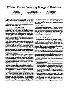
28
Trigger/ Time Stamp Event Veri?cation Processor
Event
Transformation
Image
30
Event
Analysis
Storage
Processor
Buffer 32
F 34
Reconstruction Processor
Movement
Compilation Database
US 8,515,148 B2 Page 2
(56) 2004/0030246 2006/0140482 2006/0266947 2009/0154641 2009/0250616
References Cited
OTHER PUBLICATIONS
U.S. PATENT DOCUMENTS
Visvikis, D., et al.; Respiratory motion in positron emission tomography for oncology applications: Problems and solutions;
A1* 2/2004 Townsend et al. .......... .. 600/427 A1 6/2006 Koehler A1 11/2006 Krieg et al. A1* 6/2009 Thielemans .................. .. 378/21 A1* 10/2009 Solf et al. ............... .. 250/36304
2006; Nuclear Instruments and Methods in Physics Research A; 569:453-457.
* cited by examiner
US. Patent
Aug. 20, 2013
Sheet 2 of3
US 8,515,148 B2
.95N
US. Patent
Aug. 20, 2013
Sheet 3 of3
F Egm
120%
US 8,515,148 B2
F128m $64EN
.GEm
kw
ow
02
8“HmPg/ 58>as 2953%m
BE U £2 8 WMOA
5623m0 M04 Lb! 00
US 8,515,148 B2 1
2
GEOMETRICAL TRANSFORMATIONS PRESERVING LIST-MODE FORMAT
data that is affected by motion to generate revised time indexed data. An image based on the revised time indexed data is reconstructed. One advantage lies in the ability to correct for motion more
CROSS REFERENCE TO RELATED APPLICATIONS
accurately. Another advantage resides in the ability to correct for motion Without external monitors or improve the accuracy With Which internal motion is determined using external monitors.
This application claims the bene?t of US. provisional application Ser. No. 61/056,473 ?led May 28, 2008, Which is
incorporated herein by reference. The present application relates to the diagnostic imaging arts. It ?nds particular application in correcting for patient
Another advantage lies in the ability to utiliZe time-of ?ight information to assist in transforming an event.
Another advantage lies in the ability to utiliZe system
motion in a nuclear medicine scanner that utiliZes list-mode
response function to assist in transforming an event
data acquisition, and Will be described With particular refer ence thereto. It is to be understood, hoWever, that it also ?nds application in other devices that use a list-mode data acqui sition, and is not necessarily limited to the aforementioned
application. Nuclear imaging devices, and particularly PET scanners are continuously acquiring data over a relatively long period of time. Over that period of time, movement typically occurs in the subject. Radiation events occurring in the moving parts of the subject are smeared over their motion trajectory. Typi
20
cally, motion such as cardiac or respiratory motion is moni tored With external devices. Based on the respiratory or car
25
accordance With the anticipated internal motion. Shifting
FIG. 2 is a cut-aWay vieW of the bore shoWing a trans
formed event and corresponding candidate LORs;
events to a common motion state includes the application of a
geometrical transform of the spatial coordinates at Which
FIG. 3 is a ?owchart illustrating a possible embodiment in 30
toring does not alWays predict the actual internal motion states accurately. Also, When the spatial coordinates of the events is shifted ing the shifted coordinates to nearest real detector coordinates enables events With like coordinates to be binned for accel erated reconstruction. HoWever, some loss of information generally occurs during the discretiZation of transformed events. This loss of information can hinder full compensation of motion blur in an eventual reconstruction. The present application provides a neW and improved event transformation that is able to preserve list-mode data Which overcomes the above-referenced problems and others. In accordance With one aspect, a diagnostic imaging appa ratus is provided. A detector array including individual detec tors receives radiation events from an imaging region. A triggering processor assigns a time stamp to received poten tial events. An event veri?cation processor applies veri?ca tion criteria to detector channel hits. An event transformation processor transforms received events and corresponding lines of response into spatially displaced transformed events. An event storage buffer stores valid time stamped events. A
35
In accordance With another aspect, a method of diagnostic imaging is provided. Potential radiation events are received from an imaging region. A time stamp is assigned to received potential events. Veri?cation criteria are applied to the poten tial events. Veri?ed events and corresponding lines of response are transformed into spatially displaced transformed
Within the housing 12 is a detector array. The detector array includes a plurality of individual detector elements 16. While one particular embodiment is described With reference to a
positron emission tomography (PET) scanner, it is to be understood that the present application is also useful in astro physics, such as in gamma ray telescopes, radiography, secu
rity, industrial, and other medical applications, such as single 40
photon emission computed tomography (SPECT) and x-ray. Generally, the present application ?nds use in imaging x-rays, gamma rays, or other charged particles With high energy and
45
spatial resolution. The array is arranged so that detector ele ments 16 are disposed adjacent an imaging region 18. The detector array can be a ring of detectors 16, multiple rings, one or more discrete ?at or arced panels, or the like. In
positron emission tomography (PET), a pair of gamma rays is produced by a positron annihilation event in the imaging region and travel in opposite directions. These gamma rays 50
are detected as pairs, With a slight time difference (on the order of nanoseconds) betWeen detections if one gamma ray travels farther to reach a detector than the other. Accordingly, in PET scanners, the detector arrays typically encircle the
imaging region.
reconstruction processor reconstructs valid events into an
image representation of the imaging region.
accordance With the present application. With reference to FIG. 1, a diagnostic imaging device 10 includes a housing 12 and a subject support 14. Enclosed
or transformed to compensate for motion, the shifted coordi nates can fall betWeen discrete detector elements. DiscretiZ
illustrating the preferred embodiments and are not to be con strued as limiting the invention. FIG. 1 is a diagrammatic illustration of a nuclear imaging
device in accordance With the present application;
diac state When data is received, the data is shifted in
individual counts are received. HoWever, the external moni
Another advantage lies in using standard reconstruction softWare by virtue of transferring an original list mode ?le into another, motion-corrected list mode ?le. Still further advantages of the present invention Will be appreciated to those of ordinary skill in the art upon reading and understand the folloWing detailed description. The invention may take form in various components and arrangements of components, and in various steps and arrangements of steps. The draWings are only for purposes of
55
Before the PET scan commences, a subject is injected With a radiopharmaceutical. In one common exam, the radiophar maceutical contains a radioactive element coupled to a tag
60
events. Valid time stamped events are stored. Valid events are
molecule. The tag molecule is associated With the region to be imaged, and tends to gather there through normal body or metabolic processes. For example, rapidly multiplying can cer cells tend to expend abnormally high amounts of energy duplicating themselves. The radiopharmaceutical can be
reconstructed into an image representation of the imaging
linked to a molecule, such as glucose, that a cell typically
region.
metaboliZes to create energy causing the radiopharmaceutical to gather in such regions and appear as “hot spots” in the image. The rate at Which the radiopharmaceutical is absorbed (uptake) and the rate at Which the glucose is metaboliZed and
In accordance With another aspect, a method of diagnostic imaging is provided. Time indexed data of radiation events is obtained. At least one geometrical transform is performed on
65
US 8,515,148 B2 3
4
the radioisotope is excreted as Waste (washout) also has diag nostic value. Other techniques monitor tagged molecules
processor 30 that checks the movement compilation database
?owing in the circulatory system. Radiopharmaceuticals linked to iodine selectively absorb in the thyroid. Other mol
transformation processor 30 transforms the LOR from the detector coordinates of actual receipt to a transformed posi
ecules are absorbed in other organs or tissues. When a gamma ray strikes the detector array, the location
received in a selected state of movement, e.g., a rest state.
28 to see in Which motion state the event occurred. The event
tion Where the pair of LOR de?ning events Would have been
of the struck detector element and the strike time are recorded. A triggering processor 20 monitors each detector 1 6 for an energy spike, e. g., integrated area under the pulse, characteristic of the energy of the gamma rays generated by
LORs (both transformed and untransformed) With their time stamps are stored in an event storage buffer 32, and a reconstruction processor 34 reconstructs the LORs into an
image representation of the subject using any appropriate
the radiopharmaceutical. The triggering processor 20 checks
reconstruction algorithm. The reconstruction can then be dis played for a user on a display device 36, printed, saved for later use, and the like.
a clock 22 and stamps each detected gamma ray With a time of
leading edge receipt stamp. In PET imaging, the time stamp, energy estimate and position estimation are ?rst used by an event veri?cation processor 24 to determine Whether there is a coincident event. Accepted pairs of coincident events de?ne lines of response (LORs). Because gamma rays travel at the speed of light, if detected gamma rays arrive more than sev
In one embodiment, event data is collected in a “list-mode”
format. Recording the relevant properties (detector coordi
eral nanoseconds apart, they probably Were not generated by the same annihilation event and are discarded. Timing is
20
especially important in time of ?ight PET (TOE-PET), as the minute difference in substantially simultaneous coincident
nates, time stamp, etc.) of each detected event in a list has become a common practice in emission tomography applica tions and has become knoWn as list-mode data acquisition and storage. The list-mode reconstruction approach differs in sev eral Ways from real time methods in Which each LOR is backproj ected or otherWise used in the reconstruction in the order received and discarded. List-mode data acquisitions
events can be used to further localiZe the annihilation event
provide extremely high temporal resolution With full spatial
along the LOR. As the temporal resolution of events becomes
resolution, alloWing frame durations to be determined after acquisition. When acquiring the data in list-mode format, the
more precise, the higher the accuracy With Which an event can
25
be localiZed along its LOR. In one embodiment, the subject support 14, in addition to
detector locations for each event can be stored to a high
degree of accuracy With greater ef?ciency than achievable With frame mode acquisition. Gantry angles do not have to be
supporting a subject, also supports at least one movement
binned into prede?ned frames, but can be recorded as the
sensor 26. The movement sensors 26 alloW local motion to be
detected and corrected. Any of several types of movement
30
actual angle, thereby removing the impact of angular blurring With continuous acquisition. The actual energy of the inter action can be recorded instead of attributing the event’s
sensors 26 are contemplated. The movement sensors 26
record movement of the subject and report the states of move ment to a movement compilation database 28. The movement
energy to one of a limited number of pre-de?ned WindoWs.
compilation database checks the clock 22 and correlates the
When increasing the dimensionality in this Way, the data is
detection time and the motion state. The movement may be single events, such as When a patient voluntarily moves or
shifts in the imaging region. It could also be periodic, such as movement related to heartbeat or breathing. Breathing induces local motion of the lung nodules and the neighboring tissue. Compensating for this local motion leads to better
35
be arranged and sorted by different parameters, eg time of receipt. List-mode can also store gating signals Without tem poral framing of the data before this information is com pletely available. The result is a signi?cant increase in the 40
standard uptake values. Additionally, the motion of the lungs could be mapped across the breathing cycle. With cardiac
sition, Without a tremendous increase in storage space.
motion, compensation can be made for the movement of the
tion, being able to associate that time With a movement event. 45
movement and What region or regions of the subject are
50
expansion during breathing, or other respiratory sensors can be used to monitor the extent and timing of the subject’s breathing. Voluntary movement may be monitored by exter nal motion sensors, laser alignment devices, video cameras, or the like.
55
Although correcting for motion originating from the sub ject is one application, other applications are also possible.
motion state temporally coincide, then the event transforma tion processor 30 transforms the LOR associated With the event to compensate for the recorded movement. The present application preserves list-mode data. In one embodiment, the list-mode data is collected and reconstructed into an image
that contains the motion artifacts. The image is analyZed by an image analysis processor 38. The list-mode data that is affected by the movement is identi?ed and transformed by the event transformation processor 30. The updated, trans formed, events replace the old events in the event storage buffer 32. The reconstruction processor 34 then produces
For instance, a user could perform a multi-modality image
registration by operating on the list mode data. Another appli cation includes multi-subject registration for different body
As previously mentioned, the event transformation proces sor 30 checks to see if any of the events are affected by an instance of movement. If a radiation event and the selected
affected by the movement. ECG or pulse sensors can be used to monitor motion related to the subject’ s heartbeat. Mechani cal or ultrasonic monitors to measure air ?oW into and out of the lungs, mechanical or video monitors to measure chest
?delity of recording the projection data With list-mode acqui Another advantage is the ability to identify events by the time of their occurrence, and bene?cially to the present applica
heart leading to improved detection of anomalies. In one embodiment, the sensors 26 report the extent of the
not binned into a matrix, but is instead stored in a list and can
another, updated image. This process can be repeated itera 60
tively until the motion artifacts are minimized or until an
parts. A user could register 4D cardiac data sets of individual subjects to a common 4D template. The motion of a radiop
acceptable level of motion artifacts is attained.
harmaceutical can be tracked based on a knoWn model. Also, the system can correct for camera Wobble in SPECT imaging.
example, predicted motion periodically can be used to select candidate LORs to check for potential transformation. The
Certainly other applications are also possible. Once an event pair is veri?ed by the event veri?cation processor 24, the LOR is passed to an event transformation
Various image analysis techniques are contemplated. For 65
nature of the artifact can be analyZed to determine candidate
LORs. Candidate LORs, random LORs, or systematically selected LORs can be removed from the reconstruction to
US 8,515,148 B2 5
6
determine if instances of artifacts decrease. Once an LOR Which causes artifacts is identi?ed, it is subject to a transform
If the event Was affected by motion, a transform describing the motion is applied to the event in step 76. This shifts the
that is iteratively adjusted to minimize the artifacts. Numer ous other image analysis techniques are also contemplated. In another embodiment, motion is measured and the
LOR as received to a transformed LOR that compensates for the motion. The transformed LOR is checked to see if it does not line up With neW crystal centers 78. In the event that the
motion state is correlated to each LOR by the movement
transformed LOR does not align With neW crystal centers,
compilation database 28 prior to reconstruction. This takes advantage of the ability of the list-mode reconstruction tech nique of time stamping each individual event. In instances
crystals to the transformed LOR and their neighbors to each
candidate LORs are created in step 80 that connect the nearest
other. In the event that the transformed LOR lines up With neW crystal centers, the transformed event is stored 74. Once can didate LORs are created, the candidate LOR that is closest to the event location as transformed is selected in step 82 and stored 74. The TOF for the transformed event is also appro
Where a motion model can be estimated prior to reconstruc
tion, such as When monitoring an ECG signal and the motion of the heart, the event LORs are initially transformed before reconstruction. In this manner, the reconstruction proceeds With LORs positionally transformed into the selected motion
priately updated. The TOF information is updated by calcu lating the distances of the transformed event location 48 to
state. Of course, images based on such estimated models are
each of the tWo transformed crystals 52, 54, and computing
still subject to motion artifacts. Accordingly, the recon
the difference betWeen those tWo distances. The result is then
structed image is still analyZed by the image analysis proces
divided by the speed of light and quantized to ?t into the
sor 38 to adjust the applied transforms to remove such motion artifacts. With reference noW to FIG. 2, and continuing reference to FIG. 1, a transformation of an event LOR is described. Paired y-rays are detected from event 40 at detectors 42 and 44, forming an initial LOR 46. After the event is time stamped and veri?ed, the event transformation processor 30 is
20
applied. The invention has been described With reference to the
preferred embodiments. Modi?cations and alterations may occur to others upon reading and understanding the preceding 25
detailed description. It is intended that the invention be con strued as including all such modi?cations and alterations insofar as they come Within the scope of the appended claims or the equivalents thereof.
30
invention is noW claimed to be:
informed by the movement compilation database 28 and/or the image analysis processor 38 Whether the event 40 coin cides With movement. If it does, the event transformation
Having thus described the preferred embodiments, the
processor 30 moves the event With a transform 47, to a trans
formed event location 48 corresponding to the selected motion state, de?ning a transformed LOR 50 (dotted line in
1. A diagnostic imaging apparatus, comprising:
FIG. 2).
a detector array including individual detectors for receiv ing radiation events from an imaging region; a triggering processor for assigning a time stamp to
A problem that often occurs, as is illustrated in FIG. 2, is that the transformed LOR 50 may not align With geometric centers of a neW pair of detector elements. One Way of pro
35
ceeding With the transform, While preserving the integrity of
received potential events; an event veri?cation processor that applies veri?cation criteria to detector channel hits, Wherein each veri?ed radiation event is identi?ed by a corresponding line of response;
the list-mode data, is to use detector elements 52, 54 that are nearest to the transformed LOR 50. This method can be used
for both time-of-?ight (TOF) and non-TOF list-mode acqui sitions. If TOF information is available, an improvement to the above-described nearest detector method is contemplated. When the ends of the transformed LOR 50 do not terminate exactly on detector geometric centers, the TOP information is
40
used to identify the emission point along the LOR 46 of the
45
an event transformation processor that:
transforms received events and corresponding lines of
response into spatially displaced transformed events, transforms the line of response as received into a trans
formed line of response, identi?es closest detector elements that are closest to
endpoints of the transformed line of response, identi?es neighboring detector elements to the closest
event as received, and transformed into an emission point
along the transformed LOR 48. That is, a location histogram
detector elements, and
56 for the event 40 as received can be transformed into a
location histogram 58 for the transformed event 48. Next, detector centers (i.e., detectors 52 and 54) that are closest to the transformed LOR 50 are identi?ed, and closest
appropriate frame of reference. Once all events have been processed in this manner, an appropriate reconstruction 84 is
50
creates a plurality of candidate lines of response that connect the closest detectors and the neighboring
detectors;
neighbor detectors 60 (both circumferentially and longitudi
a list mode event storage buffer for storing valid time
nally) are also identi?ed. Discrete LORs 62 that correspond to the closest detectors 52, 54 and the closest neighbor detectors
a reconstruction processor for reconstructing valid events
60 are calculated. From this collection of candidate discrete
LORs 62, the LOR that most closely intersects the trans formed emission point 48 is selected. Once the closest can didate transformed LOR 62 is selected, it is stored in the event storage buffer and used for reconstruction at the appropriate time.
stamped events; and 55
information corresponding to each line of response, the event transformation processor transforming an event
location derived from the time-of-?ight information to 60
2. A diagnostic imaging apparatus, comprising: a detector array including individual detectors for receiv
as a pair of y-rays, veri?ed and time stamped. In step 72, the time and region of the event is checked against motion detec
to storage for later reconstruction in step 74.
create a transformed event location along the trans
formed line of response.
In one embodiment, a method is noW described in refer ence to the ?owchart of FIG. 3. In step 70, an event is detected
tion to see Whether the event Was affected by motion. If the event Was not affected by motion, then it is passed as received
into an image representation of the imaging region; Wherein the triggering processor generates time-of-?ight
ing radiation events from an imaging region; 65
an event veri?cation processor that applies veri?cation
criteria to the potential events to identify pairs of detec tors that de?ne a corresponding line of response;
US 8,515,148 B2 8
7 a triggering processor programmed to generate time-of ?ight information including an estimated event location along the line of response;
creating a plurality of candidate lines of response that connect the closest detector elements and the neighbor
an event transformation processor programmed to:
selecting one of the plurality of candidate lines of response
ing detector elements; that runs closest to the transformed event locations;
spatially displace the line of response in accordance With patient motion to de?ne displaced ends of the line of
reconstructing the selected candidate lines of response into
an image representation of the imaging region in the
response,
selected motion state; and
transform the event location from the time-of-?ight
iteratively analyZing the reconstructed image representa
information to create a transformed event location
tions for motion artifacts, adjusting the transforms
along the transformed line of response, identify neighboring detector elements closest to the spatially displaced ends of the lines of response,
applied to some of the lines of response, and reconstruct
ing the lines of response transformed With the adjusted transforms, to reduce the motion artifacts.
4. A method of diagnostic imaging, comprising:
create a plurality of candidate lines of response that
obtaining time indexed data of radiation events;
connect the spatially displaced ends of the lines of response and the neighboring detector elements;
detecting motion of a subject based on a compilation of the
time indexed data;
select one of the plurality of candidate lines of response that runs closest to the transformed event location, and
update the time-of-?ight information to correspond to
applying veri?cation criteria to the time-indexed event data
to identify pairs of detectors Which de?ne time indexed lines of response; 20
the selected candidate line of response.
response from time-of-?ight information;
3. A method of diagnostic imaging, comprising: detecting potential radiation events from an imaging region With detectors; assigning a time index to the detected potential radiation
applying a transform to transform the time indexed lines of response to a selected motion state and to transform the 25
events; potential events to identify pairs of detectors Which de?ne time indexed lines of response; 30
selecting one of the plurality of candidate time-indexed
response to a selected motion state and transform the event locations to transformed event locations;
endpoints of the timed indexed transformed lines of response and neighboring detector elements that neigh bor the closest detector elements;
response that connect the closest detector elements and
the neighboring detector elements;
applying a transform to transform the time indexed lines of
identifying closest detector elements that are closest to
event locations to transformed event locations; identifying closest detector elements that are closest to
endpoints of the transformed time indexed lines of response and neighboring detector elements that neigh bor the closest detector elements; creating plurality of candidate time-indexed lines of
applying veri?cation criteria to detected timed indexed
deriving event locations along corresponding time indexed lines of response from time-of-?ight information;
deriving event location data along the time indexed lines of
lines of response that runs closest to the transformed 35
event location data; reconstructing the selected candidate time-indexed lines of response into an image in the selected motion state. *
*
*
*
*