Jan 9, 2005 - Steven Rutledge, Stephen Nesbitt, Robert Cifelli, and Timothy Lang ...... B. Chadwick, M. H. Ackley, M. F. Barth, N. L. Abshire, P. A. Miller. and T. W. Schlatter. ... F. Marks, S. Rutledge, and J. Weinman, 2002: GPM Draft Science ...
Report and Recommendations of the Global Precipitation Mission (GPM) – Ground Validation (GV) Front Range Pilot Project
Steven Rutledge, Stephen Nesbitt, Robert Cifelli, and Timothy Lang Department of Atmospheric Science – Colorado State University Brooks Martner*, Sergey Matrosov*, and David Kingsmill* Environmental Technology Laboratories – National Oceanic and Atmospheric Administration Kenneth Gage and Christopher Williams* Aeronomy Laboratory – National Oceanic and Atmospheric Administration V. Bringi and V. Chandrasekar Department of Electrical and Computer Engineering – Colorado State University Patrick Kennedy Colorado State University – CHILL National Radar Facility
Final Version 9 January 2005
Acknowledgements: This work was supported by NASA GPM-GV supplemental grant NNG04GF32A under the direction of Matthew Schwaller.
*Also affiliated with the Cooperative Institute for Research in Environmental Studies – University of Colorado
NASA–GPM–GV Front Range Pilot Project Final Report
Page 2
TABLE OF CONTENTS
Section 1: EXECUTIVE SUMARY AND PRELIMINARY RECOMMENDATIONS ...............3 Section 2: Introduction and Project Overview.............................................................................6 2.1.
Experimental design .............................................................................................................................6
Section 3. Ground Validation Instrument Candidates................................................................10 3.1.
Background .........................................................................................................................................10
3.2.
Outline of Instrument Advantages and Limitations .........................................................................12
3.3.
Specific Instrument Issues Addressed in the Pilot Project...............................................................17
Section 4. A Template for Uncertainty Analysis for GPM GV..................................................19 Section 5. Addressing our GV Objectives.................................................................................23 5.1.
S- and X- Band Polarimetric Radar Comparisons ...........................................................................23
5.2.
Profilers, Disdrometers, and Gauges for Ground Validation...........................................................24
5.3.
Polarimetric Retrievals of DSD Parameters by the 2-D Video Disdrometer (2DVD) ..................33
5.4.
Hydrometeor Identification by Polarimetric Radar..........................................................................38
APPENDIX 1. Characteristics of the Scanning Radars, Profilers, and Disdrometers Used in the Pilot Project ..............................................................................................................................41 APPENDIX 2: Comparisons of Algorithms for Calculating Kdp and Corrections to Zeh and Zdr Measurements for the Effects of Attenuation at X-band.............................................................45 A2.1.
Comparisons of Algorithms for Calculations of Kdp .....................................................................45
A2.2.
Comparisons of Algorithms for Correcting Zeh and Zdr for Attenuation Effects.........................46
APPENDIX 3: Case study results.............................................................................................48 A3.1.
9 June Case Study ...........................................................................................................................48
A3.2.
21 June 2004 Case Study................................................................................................................53
A3.3.
15 July Case Study..........................................................................................................................59
REFERENCES .........................................................................................................................65
NASA–GPM–GV Front Range Pilot Project Final Report
Page 3
Section 1: EXECUTIVE SUMARY AND PRELIMINARY RECOMMENDATIONS We are pleased to submit this report describing activities and findings from the Front Range GPM Pilot Project conducted during the summer of 2004. The purpose of the Pilot was to bring together a team of scientists and instruments to carry out preliminary design and evaluations that would aid planning for the GPM GV mid-latitude Supersite concept. The Pilot was a successful collaboration between scientists at Colorado State University (Departments of Atmospheric Science and Electrical and Computer Engineering), and NOAA’s Aeronomy Laboratory and Environmental Technology Laboratories. Approximately 20 faculty, staff and graduate students participated in the project. Some key finding of the Pilot are: X-Band polarimetric radar is capable of estimating rain rates as low as ~2 mm hr-1; polarimetric-based rain estimates at S-band begin at 5-7 mm hr-1. At rain rates less than this, S-band radars must utilize the conventional Z-R estimator, which can be subject to significant error due to variability in the drop size distribution and calibration uncertainties. Under high rain rate conditions (rates of several tens of mm hr-1) X-Band signals are subject to severe attenuation losses. While X-Band attenuation procedures have been developed, complete signal extinction can occur, rendering precipitation estimation impossible. Therefore S-Band and X-Band form a complimentary combination that can apply the more accurate polarimetric rain estimators to a wider range of rainfall rates than either could handle alone. We also offer the recommendation that two vertically pointing profilers operating at different frequencies be collocated at the Supersites. One UHF profiler operating at 449 MHz would be used to estimate the vertical air motion and the other profiler operating near 2835 MHz (S-Band) would be used to estimate the Doppler fall velocity of the raindrops. Algorithms can be developed to estimate the air motion from the 449 MHz profiler spectra and used with the 2835 MHz profiler spectra to estimate the DSD from near the surface to just below the freezing level. 2-D Video and Joss-Waldvogel momentum disdrometers proved to be invaluable in characterizing calibration and algorithm uncertainty in all radar, profiler measurements made in the Pilot Project. Based on the data and results produced by the GPM Front Range Pilot Project, we preliminarily recommend the following instrumentation suite to accomplish the GPM GV task at the GPM continental Supersite1: Dual-wavelength (S- and X-Band) scanning dual-polarization Doppler radar. As discussed in section 5 and the Appendices, this system will be the core instrument for retrieving the 4-D evolution of precipitation rates (using polarimetric measurements at rain rates greater than about 2 mm hr-1 and reflectivity alone for lighter rain) and polarimetric hydrometeor identification methodology. The instrument will collect volume scans at 5-10 minute time resolution over the Supersite Multidimensional Observing Volume (MOV), providing the 3-D hydrometeor volume inputs required the Satellite Simulator Model (SSM). 1
We are assuming that the site will be deployed at the Department of Energy ARM-CART site near Lamont, Oklahoma. This is because facilities such as regular radiosonde launches, ceilometers, microwave water vapor path sensors, etc., present at the ARM-CART site will also be required for atmospheric state variable input into microphysical retrievals made by the Multidimensional Observing Volume (MOV) and as input into the the Satellite Simulator Model (SSM).
NASA–GPM–GV Front Range Pilot Project Final Report
Page 4
To reduce uncertainty related to geometrically matching beams from two radars, it is proposed that the radar to be developed for GPM-GV have a single antenna for both wavelengths, which will be facilitated by a dual-wavelength dual-polarization feed horn currently in development by VertexRSI, Inc. While the beam width dimensions will most likely not be identical between the two radars (with the X-Band data having higher resolution than at S-Band), the pointing angles of the two frequencies will be matched such that direct comparisons (varying only in beam width) may be made between the S- and X- Band measurements. A system of this type will also provide a lower-cost alternative to a dual-antenna system or utilizing two radar systems for the radar site. Preliminary procurement cost estimate: $3-5 M. Dual-wavelength (S-Band and 449 MHz) vertically pointing Doppler radar system. The dual-frequency profiler system will provide the crucial microphysical measurement link between the scanning radars and the detailed, in situ microphysical measurements made on the ground. This system will provide measurements of radar reflectivity, vertical velocity spectra of hydrometeors (at S-Band and 449 MHz), and clear air velocity spectra (at 449 MHz) with 1 minute time resolution. This information can be used to retrieve radar reflectivity, fall speed, and DSD parameter profiles, which can be compared both to ground instrumentation measurements of the above parameters (at the lowest gate of the profilers) and to overlapping coverage with the dual-frequency radar measurements (at overlapping gates aloft). This capability will be crucial in providing a pathway to propagate uncertainty estimates between the ground sensors and the scanning polarimetric radar microphysical estimates. The profiler system will consist of 2 separate transmitter/antenna systems, due to the fact that the S-Band (449 MHz) systems are typically have an upward pointing dish (phased-array) antenna. These systems will be located side-by-side at some range from the radar about 30-40 km away from the scanning polarimetric radar, calibrated with collocated surface disdrometer(s), and require relatively little maintenance compared with a scanning radar. Preliminary procurement cost estimate: $300-400 K. Network of Surface disdrometers. This project has shown the wide applicability of the surface disdrometer as a rain rate and DSD measurement tool, as well as a calibration tool for profiling and scanning radars. Based on the scientific requirements of the Supersite, 2DVD disdrometers have demonstrated superiority relative to impact-type Joss-Waldvogel disdrometers. Outlined here are results and recommendations based on our findings, realizing that some combination in number of both types will likely be deployed due to budgetary issues. 2D video disdrometers (2DVDs). The 2DVD can provide direct in situ measurement of hydrometeor habit, number concentration, size, axis ratio, and fall speed at the surface. These measurements can be used to evaluate uncertainties in radar and profiler microphysical algorithm assumptions and retrievals. These measurements can also be used to directly simulate (and thus calibrate) profiler and scanning radar measurements of radar reflectivity Ze, as well as scanning polarimetric radar measurements of differential reflectivity Zdr and specific differential phase
NASA–GPM–GV Front Range Pilot Project Final Report
Page 5
Kdp. It is envisioned that several of these instruments will be placed at various ranges from the radar to evaluate uncertainties related to range effects in the scanning radar retrievals (which will be required to address uncertainties within the MOV), as well as at the profiler site as a validation and calibration standard for profiler measurements and retrievals. Calibration of the low-profile 2DVD used in this project has been demonstrated to be stable and straightforward, when necessary. Preliminary procurement cost estimate: 10 x $80 K each = $800 K Impact-type Joss-Waldvogel disdrometers (JWDs). This set of instrumentation can provide in situ measurements of the DSD and rain rate at the surface. The JWD incurs well-known DSD measurement errors due because of their impact-based technology, cannot measure hydrometeor shape, habit, or fall speed (these must be assumed), and are not able to be calibrated on site beyond gross comparisons with collocated gauges. Thus, these instruments provide less complete information than 2DVDs. However, they generally require less human attention in the field and can provide a lower cost alternative or supplement. Preliminary procurement cost estimate: 20 x $20 K each = $400 K Network of tipping bucket rain gauges. The Front Range Pilot Project had limited gauge resources available, such that their full utility was not demonstrated beyond point comparisons with disdrometer, profiler, and polarimetric radar rain rate estimates at the Platteville and BAO instrument sites. It is anticipated that a dense, broad rain gauge network will be required to evaluate the uncertainty in scanning polarimetric radar rainfall estimates over the MOV (10 x 10 km area). Assuming a triple redundant gauge network with 1-km resolution, this would require 300 tipping bucket gauges. However, the details of gauge network design are left to future work. Preliminary procurement cost estimate: 300 x $0.5 K each = $150 K.
NASA–GPM–GV Front Range Pilot Project Final Report
Page 6
Section 2: Introduction and Project Overview The Pilot project’s specific aims included the following: 1. Dual-wavelength radar DSD and rain rate estimate intercomparison, validation, and error characterization. Demonstration of dual-wavelength polarimetric radar network for creating rain estimates and documenting associated errors. The project used the SBand CSU-CHILL radar at Greeley, CO and NOAA-ETL’s X-Band radar at Erie, CO. The X-Band radar’s improved phase sensitivity in light rain was evaluated against the SBand radar’s performance in such conditions. The S-Band’s known insensitivity to attenuation in heavy rain was used to evaluate the X-Band radar’s ability to correct for attenuation using its specific differential phase measurements, and thus diagnose heavy rain. 2. Profiler demonstration in the supersite concept. Selection of UHF profiler frequencies that will best complement S-Band profiler measurements at a midlatitude site and allow for the most accurate retrieval of drop size distribution characteristics as a further goal of the Pilot. A ancillary goal was to perform quantitative comparisons of drop size distribution (DSD) characteristics between the profilers and scanning radars in order to evaluate assumptions in the scanning radar retrieval technique (e.g., equilibrium drop shape relationship) as well as spatial variability of the DSD. 3. Rain rate and drop size distribution characterization in the context of supersite observations, rainfall regimes. The Pilot sought to demonstrate the complementary role played by rain gauges and surface disdrometers (both 2DVD and JWD types) in determining the error characteristics of multi-frequency profiler DSD estimates and dualfrequency radar DSD and rain estimates. 2.1 Experimental design Figure 2.1 shows the instrument locations for the Pilot. The CSU-CHILL S-Band polarimetric radar was located at its home base near Greeley, CO (marked CHILL in the figure). The NOAAETL X-Band polarimentric radar was deployed near Erie, CO (marked Erie-1). Both radars scanned narrow azimuth sectors over the continuously operating ground measurement sites, where the profilers, disdrometers, rain gauges, and surface meteorological stations were situated. The ground measurement sites were located at the NOAA-University of Colorado Platteville Atmospheric Observatory near Platteville, CO, and at the NOAA Boulder Atmospheric Observatory (BAO) near Erie, CO. Ground Measurement Sites Both the BAO and Platteville sites had profilers operating at 3 frequencies: one at S-Band to measure precipitation velocity spectra (and estimate DSD), and two in the UHF band: 915 and and 449 MHz. The UHF profilers were evaluated to determine their ability: 1) to resolve both the clear air and precipitation components of the radial velocity spectra in different precipitation
NASA–GPM–GV Front Range Pilot Project Final Report
Page 7
environments (e.g., light vs. heavy rain); and 2) in concert with the S-Band profiler data, provide dual-wavelength DSD parameter retrievals with the smallest errors. Each site was instrumented with at least one JWD impact-type disdrometer, tipping-bucket rain gauge, and surface meteorological station. CSU’s 2DVD was also installed at the BAO site until the end of June, at which time it was moved to Platteville. Radar scanning The X-Band radar nominally scanned 2 low-level PPIs and 2 RHIs covering the Platteville and BAO sites. Gate to gate resolution was set to either 150 m or 112.5 meters, giving a maximum range of 38.8 or 28.8 km, respectively. The X-Band scan cycle took place over a period of one to two minutes. CHILL scanned a sector of approximately 40 degrees azimuth over the entire XBand scan sector (and the instrumented sites). RHIs were also obtained over the instrumented sites. CHILL had two scanning modes depending on the rainfall regime: (1) a high-resolution 75 m range resolution low level scan mode, and (2) a standard resolution 150 m range resolution volume scan mode with a 6-8 minute scan repeat cycle (allowing storms’ vertical reflectivity and microphysical structure to be scanned by CHILL). Project timeline The overall data collection period for the Front Range Pilot Project was 15 May through June 30, 2004. All instruments operated during this time period with very little if any downtime. Data collection continued until 23 July on a target of opportunity basis. Several nice cases were obtained in this extension period. Table 2.1 shows the cases collected during the formal data collection period of the project, as well as those collected after June 30, 2004.
NASA–GPM–GV Front Range Pilot Project Final Report Table 2.1. GPM-FRPP 2004 Case List. Key is located at the top of the table.
Page 8
NASA–GPM–GV Front Range Pilot Project Final Report
Page 9
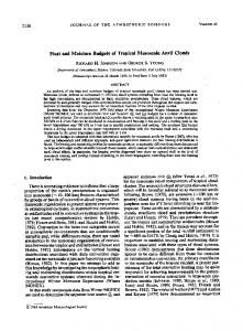
Figure 2.1. Map of the study areas showing the locations of experiment sites (bold plus signs) with instrument list, radar scan coverage areas (white lines). terrain (shaded), principal highways (grey lines), and county boundaries (thick opaque lines) also shown. KFTG is the Denver NEXRAD radar site.
NASA–GPM–GV Front Range Pilot Project Final Report
Page 10
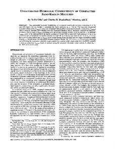
Section 3. Ground Validation Instrument Candidates 3.1. Background A preliminary conceptual plan for GPM’s continental ground validation (GV) Supersite, shown in Figure 3.1, was developed prior to the Front Range Pilot Project, based on experience obtained during the Tropical Rainfall Measurement Mission (TRMM) and on requirements of the algorithm and data assimilation communities to define error statistics of the GV measurements. Basic GV requirements include obtaining accurate, high-resolution measurements of precipitation rate and its quantitative error statistics, as well as 3-D fields of hydrometeor type, independent of the satellites, within logistical and financial constraints. No one instrument can measure these quantities alone, thus a suite of complementary instrumentation is required. Furthermore, we recognize that one continental and one maritime GV Supersite will not adequately observe the full variety of precipitation characteristics that the satellite may observe. Hence, our vision is the two Supersites will constitute a ground-based core of instruments operating unattended around the clock, 365 days a year, for the several-year lifetime of the satellite program, providing a long-term dataset that is rigorously similar in form throughout. In addition to these “routine” data, these “core” Supersites will occasionally host expanded observation campaigns to target specific questions posed by the observational or algorithm community (i.e. to validate a specific algorithm assumption). Meanwhile, auxiliary or “constellation” GV sites may also operate in other precipitation regimes (e.g. snow, coastal rain, orographic precipitation), on a more limited basis in terms of instrumentation and duration, to address algorithm issues in weather that is inadequately observed at the “core” Supersites. In this report, we address some of the primary candidate instruments from the preliminary conceptual plan for the continental GV Supersite. The Front Range Pilot Project was specifically charged with investigating the GV utility of polarimetric scanning weather radars and Doppler profiling radars. These are “big-ticket” items with long lead times that justify an early analysis effort. To accomplish this work, the use of rain gauges and raindrop disdrometers was also regarded to be essential. Therefore, the scope of this report is limited to discussing these instruments, although the GV sites may also include others. We visualize a continental GV Supersite that covers overlapping measurement scales and capabilities with a dense network of rain gauges, several raindrop disdrometers, one or more Doppler dual-frequency profiling radars, and one dual-frequency polarimetric, scanning, precipitation radar. As background, basic information about the useful attributes and known problems associated with these instruments is outlined in this section. Conventional (non-polarimetric) radar is included in the outline for comparison purposes. This outline is intended only for use in preliminary guidance and is not comprehensive.
NASA–GPM–GV Front Range Pilot Project Final Report
Figure 3.1. A preliminary conceptual vision of the continental GV Supersite.
Page 11
NASA–GPM–GV Front Range Pilot Project Final Report
Page 12
3.2. Outline of Instrument Advantages and Limitations The following tables outline the features of each instrument platform used in the Pilot Project, their capabilities, features that are attractive for their deployment at a GPM-GV site, as well as challenges and limitations that must be taken into consideration in their deployment. R = rainfall intensity, RA = rainfall accumulation, Z = radar reflectivity, DSD = drop size distribution Precipitation Gauges Physical Basis Attractive GV Attributes
Limitations & Difficulties
Measures time-resolved accumulation of precipitation mass in situ at the ground • Direct measure of R and RA at a single point on the ground. • Individual instrument is relatively inexpensive (~$500 for a very good tipping bucket gauge) • Good temporal resolution (1 minute is typical) • Instrument calibration is relatively simple • Commercially available off-the-shelf • Provides no area information, unless deployed in networks • Provides no information on precipitation aloft • Provides no information on DSD • Large, dense networks for area coverage are expensive and maintenance is manpower-intensive • Siting must avoid rain shadow of trees and buildings • Wind-induced under-catch causes underestimates of R and RA • Snowfall measurement requires more sophisticated gauges, shields, and siting • Many new gauges that are more sophisticated than the traditional tipping bucket are available commercially, but have much shorter track records
NASA–GPM–GV Front Range Pilot Project Final Report
Page 13
Raindrop Disdrometers Physical Basis Attractive GV Attributes
Limitations & Difficulties
Counts individual raindrops and determines their sizes in situ at the ground • Provides measurements of DSD, from which many other rainfall parameters can be computed, including radar reflectivity, Z • Direct measure of R and RA at a single point on the ground • Good temporal resolution (1 minute is typical) • 2DVD units also measure hydrometeor fall speeds and shapes • A valuable tool for checking scanning radar and profiling radar estimates of rain parameters • Commercially available off the shelf • Provides no area information, unless deployed in networks • Expensive (~$20K for momentum disdrometers; ~$80K for 2DVD disdrometers), thus networks of disdrometers must be relatively sparse compared to gauges • Momentum disdrometers must assume drops are falling at terminal speed • Momentum disdrometers have no feasible in-the-field calibration, although comparisons of RA with collocated gauges are useful indicators of calibration worthiness • 2DVDs require more frequent human attention than momentum units
NASA–GPM–GV Front Range Pilot Project Final Report
Page 14
Doppler Precipitation Profilers Physical Basis
Attractive GV Attributes
Limitations & Difficulties
Reflectivity and spectrum of vertical speeds of hydrometeors aloft are remotely sensed by upward pointing Doppler radar and converted to vertical profiles of information on drop size distributions • Provides profiles of precipitation conditions aloft at a single point • Continuous, unattended operation • Intermediate scale link between gauges and scanning radar sample volumes and the even larger sample volume of satellite radars and radiometers • Provides information on DSDs aloft using Doppler techniques • Provides continuous information about height of the melting layer • Provides derived information about updraft/downdraft air motions aloft • Commercially available off-the-shelf for most frequencies • Valuable tool for checking scanning radar estimates of precipitation parameters • Provides no area information, unless deployed in networks • Expensive (~$100K for 2835-MHz; ~$200K for 915-MHz) • DSD’s can be derived confidently only if clear-air and hydrometeor Doppler spectra peaks can be clearly separated; this is often difficult and may require use of two frequencies (eg., 2835 and 449 MHz) • Calibration generally requires a collocated raindrop disdrometer
NASA–GPM–GV Front Range Pilot Project Final Report
Page 15
Conventional Scanning Weather Radars Physical Basis Attractive GV Attributes
Limitations & Difficulties
Reflectivity of hydrometeors is sensed remotely, mapped in 3D, and converted to estimates of precipitation intensity using empirical Z-R relations • A single radar provides contiguous patterns of R and RA estimates over the entire satellite swatch width, typically with resolution ~1 km • Provides 3-D information on precipitation across most of the satellite swath • Operational networks are currently in place in several countries (eg. NEXRAD) • Doppler data provides information about storm airflow patterns from which storm dynamical properties can be deduced • Expensive (~$0.5-$1.0M for basic S-band system; totally autonomous systems are more expensive, NEXRAD units cost ~$10M) • R and RA are estimated from Z, rather than directly measured • Z-based estimates of R and RA are fraught with error sources associated with: o variable DSDs o improperly calibrated radar hardware o partial beam blockage (eg by terrain for low scans) o attenuation by rain (wavelengths < 10 cm) o inappropriate use of rain Z-R relations in regions of snow, melting snow, or hail • Calibration is often difficult • Provides no information on DSDs • Difficult to distinguish rain from snow or hail • Estimates of snowfall are highly inaccurate
NASA–GPM–GV Front Range Pilot Project Final Report
Page 16
Dual-Polarimetric Scanning Radars Physical Basis
Attractive GV Attributes
Limitations & Difficulties
Reflectivity, differential reflectivity, differential phase and other parameters returned from hydrometeors are measured remotely in two orthogonal polarization states, mapped in 3D, and converted to estimates of precipitation intensity, particle type, and DSD parameters using modeled relations involving particle shapes. • A single radar provides contiguous patterns of R and RA estimates and several other precipitation parameters, such as median drop diameter, over the entire satellite swatch width, with good resolution • Provides 3-D information on precipitation across much of the satellite swath • Polarimetric capability allows reflectivity to be adjusted for attenuation effects at shorter wavelengths • Doppler data provides information about storm airflow patterns from which storm dynamical properties can be deduced • Provides information on DSDs using polarimetric techniques (complements DSD retrievals from profiling radars using Doppler techniques) • Polarimetric measurables provide more accurate estimates of R and RA by avoiding many of the reflectivity-related rain estimation problems of conventional radar • Provides information for identifying particle type (raindrops, snowflakes, hail, graupel, insects, etc.) • Dual-wavelength retrievals of DSD information are possible (as will be done from the GPM-DPR) • Polarimetric measurables are useful for checking hardware calibrations • Expensive (~$3M for S-band, $1M for X-band) • Not commercially available as off-the-shelf units • Operational networks are not now available (but NEXRAD might be converted to polarimetric capability in the next decade) • Two frequencies may be required for good polarimetric estimates of R and RA over the range of heavy to light rainfall rates • Estimates of snow can benefit from the additional polarimetic information on particle shapes and from the use of two wavelengths, but these methods are still very experimental
NASA–GPM–GV Front Range Pilot Project Final Report
Page 17
3.3. Specific Instrument Issues Addressed in the Pilot Project Subsequent sections of the report focus in much greater detail on the particular radars and disdrometers used in the Pilot Project. See Appendix 1 for exact instrument characteristics of the instruments used in the Pilot Project. The emphasis of the investigations was to answer the following questions: 1. Does the addition of an X-band frequency to an S-band radar allow weaker rainfall rates to be accurately measured by polarimetric techniques? 2. What is the best frequency or combination of frequencies to be used by a Doppler profiling radar for retrieving raindrop drop size distributions (DSD) aloft? CSU and NOAA instruments were used in the Pilot Project because they were available for costeffectively testing these questions in Colorado. It is expected that the Pilot Project’s findings will provide helpful guidance for designing new, even better, GPM radars, tailored for long-term dedicated use at the continental GV Supersite. Although conventional reflectivity-based radar estimates of rainfall rate have been used for half a century, the accuracies of the estimates leave much to be desired. As shown in the outline list of Section 3b, Z-R estimates of rainfall suffer from many factors, such as DSD variability and calibration uncertainties, that commonly degrade the results. New polarimetric radars avoid many of these reflectivity-based problems and offer a large number of new measurement parameters that are related to hydrometeor shapes (Zrnic and Ryzhkov 1996, Bringi and Chandrasekar 2001). These parameters are useful for identifying hydrometeor types (raindrops, snowflakes, hailstones, etc.) and for providing information about DSD parameters, such as median drop diameter, that cannot be obtained with conventional radar, as well as for improving estimates of rain intensity and accumulation. The ability to measure these parameters with polarimetric radar is crucial for fulfillment of the GV tasks of the Supersite. Most polarimetric radar research has been conducted at S-band (10-cm wavelength), such as with CSU’s CHILL radar. Studies have shown S-band polarimetric radar using specific differential phase (Kdp) measurements can yield more accurate rainfall estimates than those available from reflectivity alone (e.g., Aydin et al. 1995, Ryzhkov and Zrnic 1996). However, this has been mainly limited to moderate to heavy rainfall situations, because Kdp is too small to measure at Sband in lighter rain dominated by small, more nearly spherical drops. Importantly, the Kdp sensitivity varies inversely with wavelength. Thus, shorter wavelength polarimetric radars, such as the NOAA/ETL X-band (3 cm), can measure the Kdp parameter and use it to estimate rain rates in lighter rainfall relative to S-Band systems. The feasibility of using X-band in this manner has been demonstrated (Matrosov et el. 2002, Anagnostou et al. 2004). Therefore, a combination using S-band (for heavy-moderate rain) and X-band (for moderate-light rain) radar with matched beams is an attractive possibility. A primary goal of the Pilot Project was to test this possibility, using available (but not ideal) resources, and to determine the range of lighter rainfall rates to which X-band can extend polarimetric rain estimation applicability. A large fraction of the global rainfall occurs at light rain intensities. Thus, these light rainfall regimes are important and cannot be ignored in climate studies that GPM is designed to support.
NASA–GPM–GV Front Range Pilot Project Final Report
Page 18
A second prime goal of the Pilot Project was to determine which frequency or combination of frequencies would be best for the Doppler profiling radar GV work. Doppler profilers have a demonstrated capability for retrieving DSD information aloft (Williams et al. 2000a). They can provide continuous vertical profiles of rain parameters, such as median drop diameter, on scales that bridge the gap between the tiny sampling volume of a rain gauge and the gigantic sample volumes of scanning radars and satellite instruments. A difficult aspect of the profiler DSD retrievals, however, involves separating peaks of the observed Doppler spectra that are caused by the terminal fall speed of the hydrometeors (Rayleigh scattering) from the peaks associated with the updraft/downdraft speeds of the air parcels (Bragg scattering) in which the precipitation particles are embedded (Williams et al. 2000b). The profiling radar measures the sum of these two contributions. However, higher frequency profilers are more sensitive to detecting the hydrometeors and lower frequencies are more sensitive to detecting the air motions (Gage et al. 1999). DSD retrieval techniques involving single and dual-frequency profilers have been developed to attack this problem. The Pilot Project used combinations of 915, 449, and 28352875-MHz from NOAA/AL and NOAA/ETL to address this issue.
NASA–GPM–GV Front Range Pilot Project Final Report
Page 19
Section 4. A Template for Uncertainty Analysis for GPM GV The ability to report quantitative uncertainty estimates in routine products generated at GPM Supersites will be a strict requirement of GV for GPM (cf., Yuter et al. 2002). This requirement will provide new challenges in understanding the error characteristics of the GV instrumentation as a function of regime (regime is defined here as a mode of precipitation type in a vertical column that defines a particular known range of microphysical and accompanying error characteristics within the spaceborne precipitation retrieval algorithms). Measurements made at the GV site must be able to not only quantify measurands and uncertainties related to observed vertical profiles of precipitation, but also be able to place those quantities within context of meteorological regime (i.e. weather and storm conditions which lead to similar storm types and thus similar error characteristics) such that error statistics determined at the GV site may be transferred to storm types, with presumably similar error characteristics, observed elsewhere by the satellites. Thus the focus of GV will not only revolve around determining measurands and uncertainties routinely required by the GPM algorithm developers, but also making the appropriate measurements to place those quantities in the context of regimes that are observed globally by the satellite. Consider a simple error model, varying as a function of regime (regimes represented by x). Recall we have defined the regime such that error characteristics are stationary within a predefined tolerance, defined by the algorithm developers. Note that the regime observed at a particular location varies as a function of time, so regimes in reality vary in both space and time. The example given here is a general form for estimating the true rain rate R(x) over a particular area using dual-frequency polarimetric radar, however it may be applied to other variables of ˆ (x) , plus interest. The GV ensemble measurements will provide their best estimate of rain rate R a total error term �(x) . In mathematical form: ˆ (x) = R(x) + �(x) . R Error sources will vary based on the measurand of interest. The following sections will define, and discuss contributions to the total error by measurement error �m (x) , parameterization error � p (x) , and sampling error �s (x) as such: �(x) = �m (x) + � p (x) + �s (x) . Measurement error Within the GVS, measurement error will encompass both the instrumental and statistical uncertainties related to making a finite sample of measurements of the GV parameters. This will include calibration uncertainty (bias offsets) as well as random statistical fluctuations in the data (random perturbations). For the example of rain rate estimation with polarimetric radar data, Zand Zdr-based rainfall estimators will be most affected by radar calibration uncertainty. This calibration uncertainty may be addressed with techniques ranging from polarimetric selfconsistency checks (Gorgucci et al. 1996, Carey and Rutledge 2000) to reflectivity, differential reflectivity, and specific differential phase comparisons with other instrumentation such as profilers, impact and video disdrometers, and rain gauges (Gage et al. 2000, Schuur et al. 2001). However, all measured input variables will be subject to statistical uncertainties. For example, statistical uncertainty in Kdp–estimated rain rates may be calculated as a function of the measured
NASA–GPM–GV Front Range Pilot Project Final Report
Page 20
standard deviation of total differential phase � (�dp ) with the following (Gorgucci et al 1999, Bringi and Chandrasekar 2001): � (�dp ) � c �1/ b � (�m ) 3 =b , R [N � (1/N)] � R � L where b, and c are the coefficients in the R-Kdp relationship, L is the path length over which Kdp is calculated, and N is the number of points within that path length. Variability in measurement error can be reduced through spatial averaging of the data, however, this cannot be done without introducing representativeness (sampling) uncertainty when comparing rain rates with rain rates measured by instruments of different sample volumes such as disdrometers or rain gauges (Tustison et al. 2001). Moreover, spatial averaging to reduce errors in Kdp can introduce errors due to non-uniformity along the path length (Gorgucci et al. 2000). Parameterization Error Parameterization error revolves around uncertainties within the inversion process of converting measured quantities (i.e. radar reflectivity Z, differential reflectivity Zdr, specific differential phase Kdp in the case of a polarimetric radar) into derived quantities (i.e. rain rate R, massweighted mean drop diameter Dm, normalized intercept parameter Nw, etc.). In other words, it is a quantitative assessment of uncertainties introduced by the model and assumptions selected to derive a particular quantity. For most quantities measured at the GVS, this uncertainty will be a strong function of the regime examined, as precipitation characteristics will directly impact the validity of the assumptions used. For example, DSD assumptions in the radar algorithm will be a strong function of regime, and measurements with known uncertainty can be placed in the context of these regimes. For the example of a polarimetric radar rainfall algorithm, parameterization error will arise when the natural variability of the parametric form of the drop size distribution or size-shape relationship differs from the assumed form. See Figure 4.1 for an example of how DSD measurements may be used to quantify rainfall algorithm parameterizations, in this case for drop axis ratio. Within the GVS, these error sources may be quantified through comparisons of the polarimetric radar assumptions and DSD measurements provided by profilers, impact and video disdrometers, or targeted aircraft observations. Representativeness error Tustison et al. (2001) and Tustison et al. (2003) are pioneering works quantifying representativeness (or sampling) uncertainties related to comparing precipitation measurements and estimates with differing sampling resolutions. As such, the Tustison et al. studies provide a template for defining sampling uncertainty at the GV site. Algorithms of this type must be generalized for the GVS to estimate this source of uncertainty in comparing measurements ranging in scale from the gauge and disdrometer sampling area scales (effective sampling volumes of O ~ 100-101 m3), to profiler and scanning radar sampling areas
NASA–GPM–GV Front Range Pilot Project Final Report
Page 21
(O ~ 105-107 m3), to the satellite pixel scale (O ~ 1010 m3). In addition, the impact of differences in temporal sampling among GVS instruments and satellite measurands must be quantified (Kummerow et al. 2000 addresses this, albeit indirectly). The design of the GVS, specifically matching the beams of the dual-frequency system and the strategic placement of surface gauges, disdrometers, and profilers) must take into account the ability to quantify representativeness error both in a spatial and temporal sense. Synthesis Measurements and uncertainties from the various GVS instruments provide the basis for construction of a GVS error model. This model will be constructed using the methodology discussed above for the three error sources. Figure 4.2 shows a conceptual diagram, indicating how this would be addressed for a polarimetric radar rain rate algorithm. The suite of GVS and ancillary observations will be used for the following two tasks: (1) generate regime-dependent error statistics or “lookup table” of regime-observation covariance statistics by generating a catalog of regime-dependent error statistics that may be applied to radar measurements (i.e. generate regime-dependent �(x) = �m (x) + � p (x) + �s (x) ), and (2) use the “lookup” table above and available observations to report the best estimate of the parameter of interest (i.e. Rˆ ± � at the radar pixel) Task (1) provides an objective transfer standard that can be used to assess precipitation errors around the globe, outside the Supersite and constellation sites. Task (2) provides the information necessary for algorithm developers to quantitatively assess the assumptions in their radiative transfer models and determine where the largest amount of uncertainty remains.
NASA–GPM–GV Front Range Pilot Project Final Report
Page 22
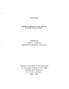
Figure 4.1. Figure 7.2 from Bringi and Chandrasekar (2001) showing experimental variability in axis ratio relationships relative to two functional fits to the data. The 2DVD, when deployed to the Supersite(s) will allow routine examination of this parameter, thus allowing characterization in uncertainty related to this assumption.
Figure 4.2. Diagram summarizing error analysis procedure for radar surface rain estimates.
NASA–GPM–GV Front Range Pilot Project Final Report
Page 23
Section 5. Addressing our GV Objectives 5.1.
S- and X- Band Polarimetric Radar Comparisons
Validation of the precipitation and microphysical estimates formulated by the GPM satelliteborne sensors is critically dependent upon obtaining an accurate characterization of the hydrometeor properties within the satellite’s sampling volume. Mesoscale precipitation systems typically contain atmospheric volumes that amount to many thousands of cubic kilometers. Scanning meteorological radar systems afford the most practical method of collecting threedimensional observations of these precipitation systems in a timely manner (i.e., volume scan cycle times on the order of two to five minutes). Prior research has established that dual-polarization radar techniques provide improvements in the accuracy of radar estimates of the instantaneous rain rate over traditional reflectivity-only radar technology. Differential reflectivity (Zdr), which is the ratio of the measured horizontal and vertical radar reflectivities, provides information on the drop size distribution within the radar volume in rain-only situations, thus providing an important constraint on rain rate and microphysical retrievals. In addition, the difference between the phases of the horizontally and vertically polarized return signals has been found to be a useful indicator of the existence of the oblate (larger diameter) raindrops that are typically present at higher rain rates, especially in mixed-phase environments where reflectivity (Z) and differential reflectivity (Zdr) rainfall estimation methods fail. For a given drop diameter, the magnitude of this differential propagation phase shift (�dp) is inversely related to the radar wavelength. Thus, the propagation phase shift (Kdp) observed by a short wavelength radar (i.e. 3 cm or X-Band) will be greater than that observed by a long wavelength radar (i.e. 11 cm or S-Band) when both systems are viewing the same precipitation path. While X-Band systems provide more sensitive Kdp retrievals, they are also subject to attenuation in their Z and thus Zdr measurements in moderate to heavy rain, often becoming completely attenuated when propagating through paths of heavy rain. Thus, the S-Band system provides rain and microphysical retrievals in this situation where Kdp sensitivity is not an issue. Furthermore, the estimation of Kdp from differential propagation phase in heavy rain or mixed phase precipitation can prove difficult at X-band. A major goal of the Front Range Pilot Project was the exploration of the differences in polarimetric rainfall estimation and microphysical measurement capabilities at S and X-Bands (11 and 3.2 cm wavelengths). Detailed case study results are presented in the appendices of this report. A few key findings may be summarized as follows: 1.) X-Band radar is capable of detecting useable Kdp magnitudes in rain rates as low as ~2 mm hr-1; useable S-Band Kdp data cannot be obtained at these low rain rates. (21 June 2004 event; Appendix section 2.2 2.) The smallest reliabily detectable S-Band �dp range gradient (Kdp) is ~0.1o km-1. This corresponds to a rain rate of approximately 5-7 mm hr-1. The results in all three cases in Appendix 2 show that X-Band Kdp estimators are thus able to perform over a significantly larger area and extend polarimetric rain estimation capabilities lower into the rain rate distribution than those at S-Band.
NASA–GPM–GV Front Range Pilot Project Final Report
Page 24
3.) Under high rain rate conditions (rates of several tens of mm hr-1) X-Band signals are subject to severe attenuation losses. While X-Band attenuation procedures have been developed, complete signal extinction can occur. (9 June 2004 case; Appendix section 2.1; also Appendix 1b). 4.) Both S- and X-Band multiparameter radar measurements (Z, Zdr, Kdp) may be used to estimate parameters of the rain DSD, such as parameters of the gamma DSD (Dm, Nw; Ulbrich 1983). Appendix 2 sections b and c show comparisons of ground-based and profiler-based Dm estimates with S- and X-Band estimates of Dm collected during the GPM Pilot Project. 5.) Hydrometeor Identification may be employed reliably at both S- and X-Band in order to identify appropriate hydrometeor types within the radar scanning volume. See Section 5.4 for further discussion of the utility and implementation of hydrometeor ID for polarimetric radars for GPM. In summary, the ground-based scanning radar data collected during the Front Range Pilot Project explored the utility of X and S-Band polarimetric radar measurements under a wide variety of warm season precipitation regimes. The increased �dp sensitivity at X-Band allows the improved accuracy of polarimetric rain rate estimation to be realized at rain rates as low as ~2 mm hr-1. At these low rain rates, the S-Band �dp signal is too noisy to be useful; rain rates must reach levels of ~5 – 7 mm hr-1 to obtain stable �dp range profiles at S-Band. However, to overcome the attenuation losses that impact X-Band measurements, S-Band observations are required to make rain rate estimates through long (several tens of kilometers), moderate-to-heavy precipitation-filled beam paths. In view of these results, to provide accurate rain rate estimations over the widest range of precipitation intensities, GPM satellite ground validation studies should make use of polarimetric radar data collected at both X and S-bands. Serious consideration should also be given to collocating the X and S-Band radars that cover the ground validation site, since this would ensure that the collection of �dp data takes place with high time synchronization along a common beam path. The use of a single antenna site would also improve cost efficiency by permitting the two radars to share the expenses associated with site leasing, installation of commercial power and data communication lines, etc. A well-chosen radar site would provide high resolution, three-dimensional scan coverage over the other ground-based sensors (disdrometers, profilers, rain gauges, etc.) that are required to collect GPM validation data. 5.2.
Profilers, Disdrometers, and Gauges for Ground Validation
With NASA support the NOAA Aeronomy Laboratory (AL) has gained considerable experience using precipitation profilers to study the structure, evolution and variability of precipitating clouds. Precipitation measurements can be made with sufficient vertical resolution to categorize precipitation in deep and shallow convective systems and in stratiform systems. A recent focus of AL research with profilers has been to provide calibration and validation in support of satellite precipitation measurement missions such as the NASA Tropical Rainfall Measuring Mission
NASA–GPM–GV Front Range Pilot Project Final Report
Page 25
(TRMM). Observations obtained by AL for TRMM during TRMM Ground Validation field campaigns have provided important information on the vertical structure and temporal evolution of precipitating cloud systems (Gage et al., 2000, 2002). The TRMM profiler observations can be viewed on the AL web page (www.al.noaa.gov). Observations made during the field campaigns have been the subject of collaborative research with other TRMM researchers with an emphasis on the use of profilers to calibrate scanning radars used for TRMM ground validation research and the use of profilers to retrieve drop-size distributions and related precipitation parameters of interest to the TRMM Science Team. Validation of drop-size distributions used in algorithms is key to improving the retrieval of rainfall estimates from the TRMM satellite data. The profiler-based precipitation research described above also can be used to provide calibration of NEXRAD scanning radars as has recently been demonstrated for Melbourne, Florida. In related activities the Aeronomy Laboratory has teamed with the Environmental Technology Laboratory (ETL) in hydrometeorological studies in relation to the PACJET campaign on the California coast and on microphysical process studies utilizing profilers in the North American Monsoon Experiment (NAME). Results of several field campaigns indicate that profilers used together with disdrometers and rain gauges provide an effective independent means for calibration and validation of scanning radar estimates of precipitation. We briefly outline below the combined use of these instruments to provide reference precipitation parameters with error characteristics to monitor and continuously validate precipitation estimates from the scanning radar. The domain of interest is on the order of 10 km � 10 km and the data collected as outlined here could be a primary component of real-time observations supporting any ground validation Supersite. Used with disdrometers and rain gauges profilers can provide an efficient means for tying ground-based observations from in situ sensors with the scanning radar observations at altitude. The profiler has an observing volume intermediate between the relatively small observing volume of rain gauges and disdrometers and the much larger observing volume of the scanning radar. It is problematic to utilize the ground-based in situ sensors to directly calibrate the scanning radar owing to the spatial separation of the surface measurements from the radar measurements at altitude and the large difference in observing volumes between the scanning radar and the in situ surface instruments. In the remainder of this section we focus on the use of the profiler as a transfer standard by comparing disdrometer and profiler measurements and profiler measurements with scanning radar observations. Here, we utilize recent studies by Gage et al. (2004) and Williams et al. (2005) to establish the precision of profiler and disdrometer measurements and to compare profiler and scanning radar observations. We also draw upon the GPM Front Range Pilot Study observations to illustrate the utility of combining these instruments in any ground validation effort. Gage et al. (2004) compared two collocated JWDs at Wallops Island to show that the precision of reflectivity determined from these instruments is about 1.5 dBZ for one minute samples. These authors also show that the reflectivity difference from the collocated instruments is nearly normally distributed in dBZ space and uncorrelated in time implying that mean reflectivities measured by these instruments can be obtained with a precision equal to the standard error of the
NASA–GPM–GV Front Range Pilot Project Final Report
Page 26
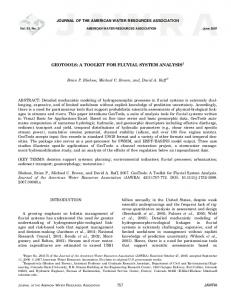
mean. In a similar fashion Gage et al. (2004) and Williams et al. (2005) determine the precision of one minute profiler reflectivities from collocated instruments to be approximately 0.5 dBZ. The precision of the profiler measurement is better than the precision of the disdrometer reflectivities owing to the averaging inherent in a larger sampling volume. The precision values quoted above are for stratiform precipitation and values for precipitation in highly convective conditions will be larger. The precision of measurement from the disdrometer and profiler instruments is good enough that the disdrometer can be used for absolute calibration of the profiler. The disdrometer also provides validation of the DSD parameters retrieved from the profiler. Figure 5.2.1 reproduces time-height cross-sections of the precipitation event of 16 – 17 June 2004 as seen at the BAO by the 2835 MHz profiler. This event was unusual since it included a period of very light rain that was confined to the lowest 1-2 km above the surface followed by a sequence of convective showers that continued through the remainder of the day. Thus, a great variety of conditions are represented in this event. The profiler contribution is immediately evident in its ability to clearly show the vertical structure of the precipitating clouds and their evolution throughout the day. Time series of reflectivity from the JWD and the profiler at the second range gate centered at 316 m AGL are compared in Figure 5.2.2 with a scatter plot shown in Figure 5.2.3. The comparisons in Figure 5.2.3 highlight the statistical behavior of the reflectivity differences between the two instruments as a function of the JWD reflectivity. Note that the disdrometer appears to overestimate reflectivities compared to the profiler at low reflectivities where the observations in this event are most numerous. There is also a tendency for the disdrometer to underestimate reflectivities compared to the profiler at high reflectivities. This reflectivity dependent bias is inconsistent with the statistical bias associated with different size sampling volumes. We have noted these tendencies in other data sets and it now appears that they are associated with the disdrometer. These features need to be understood better in order to have complete confidence in the disdrometer for absolute calibration of the profiler. DSD Estimates from the S-band Profiler Compared with the JWD While continuous calibration and validation of other ground-based instruments is an important component of the Supersite observational program, the most important aspect is the use of the ground-based instruments to provide a reliable estimate of DSD parameters and their uncertainties. The GPM Front Range Pilot provided an opportunity to demonstrate the ability of the ground-based instruments to yield estimates of the DSD parameters within selected case studies. Below, we examine results from the 16-17 June case study. There are several different forms of the drops size distribution N(D) in common use. For the purposes of this report we cite two of the more commonly used forms. The exponential distribution (Marshall and Palmer 1948) is N(D) = N0 exp (-�D)
(5.2.1)
NASA–GPM–GV Front Range Pilot Project Final Report
Page 27
where N0 is the intercept parameter and � is the slope parameter. The exponential distribution has 2 parameters and a Gamma DSD (Ulbrich, 1983) has an additional shape parameter µ and is expressed � 4+µ � (5.2.2) N ( D) = N 0 D µ exp(� �D ) = N 0 D µ exp�� � D �� D m � � where Dm is the mean mass-weighted diameter defined by N ( D) D 4 dD � Dm = (5.2.3) 3 N D D dD ( ) � for any DSD and by
Dm = µ + 4 / �
(5.2.4)
for a Gamma DSD. When µ= 0, the Gamma distribution reduces to the two parameter exponential distribution. In recent years it is becoming more common for the DSD to be represented by a normalized DSD as given by Bringi and Chandrasekhar (2001) as Nnorm(D) = N(D)/Nw
(5.2.5)
The normalizing factor Nw includes contributions from the total liquid water content W and the mean drop size of the DSD (Dm). The normalization allows the shapes of different DSDs from different rain regimes to be compared relative to the total liquid water content and the mean drop size. The normalizing factor can be estimed from 10 3W (4.0) 4 (5.2.6) Nw = �� w Dm4 While the normalized DSD is expressed using 3 parameters, only 2 of these are directly related to physical processes. Nw represents the amplitude scaling of the DSD and Dm represents the mean drop size of the DSD. To estimate the width of the DSD in the liquid water content domain �m,, the parameters Dm and µ need to be combined using the second moment of the DSD
� m2 =
�N
w
�4+µ � ( D � Dm ) 2 D 3+ µ exp� D dD � Dm � �4+µ � 3+ µ � N w D exp�� Dm D �dD
(5.2.7)
The 16-17 June case provides an excellent opportunity to compare DSD parameters using the JWD and the 2835 MHz profiler. Figure 5.2.4 shows time series of Nw, Dm and �m retrieved from the second range gate of the S-band profiler centered 316 meters above the ground at the BAO in comparison with the values obtained from the JWD at the surface. While more work will be needed to completely define the error characteristics of these estimates, the agreement of these estimates is encouraging. A case study is presented next to support the recommendation that two vertically-pointing profilers operating at different frequencies be collocated at the Supersites. One profiler operating
NASA–GPM–GV Front Range Pilot Project Final Report
Page 28
at 449 MHz would be used to estimate the vertical air motion and the other profiler operating at 2835 MHz would be used to estimate the Doppler fall velocity of the raindrops. Algorithms would be developed to estimate the air motion from the 449 MHz profiler spectra and used with the 2835 MHz profiler spectra to estimate the DSD from near the surface to just below the freezing level. Why use Different Frequency Profilers? Vertically-pointing Doppler radars used as precipitation profilers measure the Doppler velocity of hydrometeors at discrete velocity intervals at each radar range gate. Using the principle that raindrops of a particular size fall at a pre-determined fallspeed in still air, the power detected at each discrete velocity interval can be converted into the number of raindrops at that particular raindrop size. Thus, the raindrop size distribution (DSD) estimate from profiling radar observations can be viewed as a coordinate transformation from power and fallspeed to number of drops and diameter size. Two of the largest unknowns in DSDs retrieved from profiler observations are the vertical air motion and the amount of turbulence and wind shear within the radar pulse volume. The measured Doppler velocity at each discrete velocity interval is the combination of the raindrop terminal fallspeed and the air motion acting on the raindrops. Not knowing the air motion causes errors in the retrieved DSDs because the uncorrected spectra are shifted towards larger drops in downdrafts and shifted toward smaller drops in updrafts. Since the total reflectivity is conserved in this coordinate transformation, uncorrected spectra associated with raindrops in downdrafts will have fewer large drops and less rain amount than the correctly shifted spectra. Smaller drops and more rain are erroneously estimated for uncorrected spectra that are associated with updrafts. See Williams (2002) for more details. The influence of turbulence and wind shear within the radar pulse volume tends to spread the power associated with one size of raindrop into several velocity intervals. Thus, the Doppler velocity spectrum is broader than a spectrum that would be produced in non-turbulent and motionless air. To estimate the DSD, the observed Doppler velocity spectrum is modeled as a convolution of the unknown DSD fallspeed velocity spectrum and the broadening caused by the turbulence and wind shear effects. While the influence of spectral broadening will be addressed in modeling the DSD, the influence of the air motion needs to be resolved by direct measurements of the vertical air motion using profiling radars. There are several factors that must be considered when determining which profiler operating frequency should be used to estimate the vertical air motion during precipitation events. Radars with longer wavelengths (50, 449 and 915 MHz operating frequencies) can detect the vertical air motion through scattering off of refractivity turbulence (Bragg scattering). While these radars may detect precipitation, radars with shorter wavelengths (449, 915, 2835 MHz and 35 GHz operating frequencies) are much more sensitive to hydrometeors through scattering off of the distributed hard targets (Rayleigh scattering and Mie scattering at 10 GHz and above). The use of two profilers operating at two frequencies enables the air motion to be estimated with one profiler and the precipitation motion to be estimated with the other under nearly all meteorological conditions.
NASA–GPM–GV Front Range Pilot Project Final Report
Page 29
The longer wavelength profilers should be used to estimate the vertical air motion since they are more sensitive to Bragg scattering. The downside of using longer wavelength radars includes larger antennas, the increased altitude of the lowest first usable range gate and the long time required between recorded Doppler velocity spectra for the multiple radar samples that are needed to improve the signal-to-noise ratio. The benefits of using higher frequency profilers to detect the precipitation motion include stable transmitters that enable better estimates of the reflectivity and shorter dwell times needed to acquire the spectra. The use of two profilers in the FRPP to retrieve estimates of DSD parameters is illustrated next using the example of 17 June 2004. Panels (a) - (c) in Figure 5.2.5 show the Doppler velocity spectra profiles observed from the 449, 915, and 2835 MHz profilers at 1:31 UTC on 17 June 2004. These profiles are associated with the more intense portion of the rain event of 17 June with the freezing level near 2 km as indicated by the change in Doppler velocity from ~2 to ~8 m s-1 downward corresponding with the change in fallspeed of ice/snow melting into raindrops shown in Figure 5.2.5b. The black lines placed on top of the spectra profiles correspond to the altitude adjusted fallspeeds of individual raindrops with 1, 3, and 6 mm diameters. Panel (d) of Figure 5.2.5 shows the Doppler velocity spectra from each profiler at the altitude of 750 meters. The air motion peak is resolved by the 449 and 915 MHz profilers, but is not resolved by the 2835 MHz profiler. This shows that both the 449 and 915 MHz profilers are sensitive to the Bragg scattering with the 449 MHz profiler being more sensitive than the 915 MHz profiler. All three profilers are sensitive to the Rayleigh scattering from the raindrops and show very good agreement in the precipitation portion of the Doppler velocity spectra. While the 449 MHz profiler can detect the air motion peak in the Doppler velocity spectrum, sophisticated algorithms are still needed to identify the air motion peak that is 3 orders of magnitude smaller than the peak in the precipitation signal. Also, while this example shows a relatively clean 449 MHz spectrum, many spectra have noise fluctuations that are comparable in size with the air motion peak. A multiple peak-picking routine was applied to the 449 MHz profiler spectra with the air motion estimate shown as black asterisks in Panel (a) of Figure 5.2.5. Only the air motion estimates up to 2.2 km altitude are shown. Note that the air motion spectral peak is very hard to distinguish in the 915 MHz profiler observations and not present in the 2835 MHz profiler observations. From this analysis, it is recommended that two profilers operating at two different frequencies be collocated at the Supersites. One profiler operating at 449 MHz would be used to estimate the vertical air motion and the other profiler operating at 2835 MHz would be used to estimate the Doppler motion of the raindrops. Algorithms would be developed to estimate the air motion from the 449 MHz profiler spectra and used with the 2835 MHz profiler spectra to estimate the DSD from near the surface to just below the freezing level.
NASA–GPM–GV Front Range Pilot Project Final Report
Page 30
Figure 5.2.1. Time-altitude cross-sections of (a) reflectivity, (b) mean Doppler velocity, and (c) spectral width measured by the BAO S-band profiler for the 16-17 June 2004 rain event.
NASA–GPM–GV Front Range Pilot Project Final Report
Page 31
Figure 5.2.2. Time series of JWD reflectivity (red) and S-band profiler reflectivity (blue) at 316 m above the ground for the 16-17 June 2004 rain event.
Figure 5.2.3. Scatter plot of JWD reflectivity and S-band reflectivity at 316 m above the ground for the 16-17 June 2004 rain event. Panel (a) shows the probability distribution function (PDF) of the reflectivity difference (S-band JWD), Panel (b) shows the scatter plot of values, and Panel (c) shows the PDF of JWD reflectivity.
NASA–GPM–GV Front Range Pilot Project Final Report
Page 32
Figure 5.2.4. Rain drop size parameters estimated from the JWD (blue) and S-band profiler at 316 m above the ground (red). Panel (a) shows the Generalized Intercept Parameter, Nw, Panel (b) shows mean drop diameter, Dm, and Panel (c) shows the standard deviation of the Mass spectrum, �.
NASA–GPM–GV Front Range Pilot Project Final Report
Page 33
Figure 5.2.5. Simultaneous spectra obtained from the three different frequency profilers at BAO. Panels (a), (b), and (c) shows the vertical profile of spectra collected from the 449 MHz, 915 MHz, and 2835 MHz profilers. Panel (d) shows the spectra for each profiler at the altitude of 750 meters above the ground. The air motion (Bragg scattering) portion of the spectrum occurs around 0 m s-1, and the raindrop motion (Rayleigh scattering) portion of the spectrum occurs at more downward velocities.
5.3.
Polarimetric Retrievals of DSD Parameters by the 2-D Video Disdrometer (2DVD)
This section describes the measurements provided by the 2DVD as deployed for the Pilot Project, as well as describes the methodology of comparing 2DVD measurements with those from scanning polarimetric radar. Measurements from the 2DVD can be used to directly measure the drop size distribution (DSD), rain rate, and particle fall speed through its optical technology (see Figure 5.3.1 for a schematic, Figure 5.3.2 for fall speeds measured during the Pilot Project). Here, the DSD is assumed to be of the normalized gamma form with parameters Nw, Dm and µ. Here, Nw is the normalized ‘intercept’ parameter (in mm-1 m-3), Dm is the mass-weighted mean diameter (in mm) and µ is the
NASA–GPM–GV Front Range Pilot Project Final Report
Page 34
shape of the DSD. The 1-min averaged N(D) is fitted to the normalized gamma form. Histograms of Do (median volume diameter which is close to Dm) and log10(Nw) are shown in Figures 5.3.3 and 5.3.4 for all the data gathered during the GPM-Pilot program. These histograms are mostly representative of stratiform rain. The average Do is 1.08 mm and average Nw is around 2500 mm1 m-3 (which can be compared to the Marshall-Palmer value of 8000). The average µ was found to be close to 4. For Rayleigh scattering, the functional relationships Zh=f1(µ)Nw Dm7, Kdp=f2(µ)Nw Dm5, and Zdr-1=f3(µ) Dm2 can be established (note that here Zdr is the ratio of reflectivites = Zh/Zv). From these functional relations it is possible, via simulations, to construct algorithms for estimating Nw, Dm and (to a lesser accuracy) the shape parameter (µ) from radar measurements of Zh, Zdr and Kdp (e.g., Gorgucci et al 2002). While such algorithms have been developed and applied at S-, C- and Xbands, the effects of attenuation at C- and X-bands implies that attenuation-correction procedures must be applied for Zh and Zdr prior to estimation of the DSD parameters. The 2DVD gamma DSD can also be used to simulate the radar observables such as Zh, Zdr and Kdp and these can be compared with the corresponding radar measurements made by the NOAA/X-Band radar as illustrated in Figure 5.3.5. The standard error bars for the 2DVD data are based on expected sampling errors (sensing area= 100 cm2, time integration=1 min) while those for the radar are based on expected fluctuation errors. The radar data have been averaged over a 700 � 700 m area centered over the location of the 2DVD. The bias in Zh was determined to be –2.7 dB. The bias in Zdr was determined to be very small (40 dBZ. This bias can be explained by slightly different drop shape models used by ETL and CSU. Given that a typical uncertainty of reflectivity measurements is about 1 dB, the agreement between the two methods for correcting reflectivity data should be considered quite satisfactory. Figure A2.3 shows comparisons of corrected Zdr values calculated with the CSU and ETL algorithms. Both algorithms scale differential attenuation corrections linearly with measured differential phase shift, although CSU uses an additional constraint, which assumes that Zdr at the far reaches of good data in each beam is equal to the mean Zdr that corresponds to the observed value of corrected reflectivity there. Due to this constraint, the coefficient between Zdr correction and differential phase in the CSU correction scheme changes from beam-to-beam, while in the ETL algorithm this coefficient is constant for the entire data set. Figure A2.3 shows the algorithm differences, on average, do not result in significant differences of the corrected Zdr values. The mean bias between CSU and ETL data is close to 0 dB for Zdr < 2 dB, and is slightly negative (of the order 0.1 -0.2 dB, which is close to the uncertainty of differential reflectivity measurements) for larger Zdr values. Again, the agreement is quite satisfactory. Overall, the results presented in this appendix indicate consistency in the procedures. The more mature S-band algorithms showed good agreement with the ones more recently developed independently for X-band. The agreement reinforces our confidence that these basic measurement and correction schemes are working properly.
NASA–GPM–GV Front Range Pilot Project Final Report
Page 47
Figure A2.1 Scatter-plot of Kdp (dB/km) values calculated using the NOAA/ETL and CSU algorithms (left frame) and the corresponding difference (right frame). Colors represent density of points in log scale.
Figure A2.2. Scatter-plot of corrected reflectivities (dBZ) calculated using the NOAA ETL and CSU algorithms (left) and the corresponding difference (right). Colors represent density of points in log scale.
Figure A2.3. Same as Figure A2 but for differential reflectivity (dB).
NASA–GPM–GV Front Range Pilot Project Final Report
Page 48
APPENDIX 3: Case study results A3.1. 9 June Case Study An example of the basic pros and cons of rainfall estimations using X-Band radar: The 9 June 2004 GPM Front Range Pilot Project case. The use of polarimetric technology has been found to improve the accuracy of radar-based rainfall estimation as compared to the results obtained using only the intensity (reflectivity) of the return signal. This improvement is due the ability of dual polarization radars to remotely sense critical physical characteristics of the illuminated precipitation particles such their mean axis ratio, degree of preferential orientation, etc. Useful polarimetric measurements in precipitation can be made at both 11 cm (S-Band) and 3 cm (X-Band) radar wavelengths. Each wavelength, however, presents somewhat different strengths and weaknesses in the remote measurement of the full spectrum of rainfall rates. The exploration of these wavelength-dependent differences was a major goal of the GPM Front Range Pilot Project. At shorter radar wavelengths such as 3 cm, signal attenuation presents a major restriction to data collection in heavy rainfall conditions. Propagation through heavy rainfall (several 10s of mm per hour rain rates) removes significant amounts of energy from a short wavelength radar pulse. The path integrated attenuation losses can become so great that no detectable signal is returned to the radar. In contrast, at the longer 11 cm wavelength, signal attenuation losses are usually negligible. An example of this attenuation difference is provided in the data collected during the afternoon hours of 9 June 2004. Several strong thunderstorms moved across the Pilot Project network on this day. At 2228 UTC one such storm was located approximately 80 km south southwest of the CSU-CHILL radar. A Plan Position Indicator (PPI) plot of the CSU-CHILL reflectivity field at the 0.5o elevation is shown in Figure A3.1.1a. The intense (> ~45 dBZ) portion of the echo is organized into an asymmetrical “Y” shape centered near X= -22, Y= -65 km. The corresponding X-Band depiction of the storm as seen by the NOAA radar is shown in Figure A3.1.1b. Since the storm is closer to the NOAA radar, the 1.8o PPI sweep is shown. (The rings depict the beam heights in km above the radar). The two PPI scans shown in Figure A3.1.1 were made within 20 seconds of each other. An attenuation correction based on the accumulated propagation differential phase (�dp) has been applied to the X-Band reflectivity data. (�dp is the phase difference between the horizontally and vertically polarized return signals at a common range location. The development of a significant lag in the H phase return relative to that of the V phase indicates that the beam has propagated through many oblate (large) raindrops, implying that appreciable signal attenuation has occurred). The general “Y” shaped echo pattern seen in the CHILL data is also present in the X-Band plot. However, attenuation effects have weakened portions of the right hand branch of the “Y”. Signal attenuation is complete at NOAA radar ranges beyond the point marked by an X (X=14, Y= -28 in Figure A3.1.1b). This same geographic location is also marked with an X in the unattenuated CSU-CHILL reflectivity plot
NASA–GPM–GV Front Range Pilot Project Final Report
Page 49
(X=-19, Y=-65.5 in Figure A3.1.1a). A general inspection of the PPI plots from the two radars shows that severe attenuation has resulted in a complete loss of echo detection by the X-Band radar in the southeastern portions of the storm. While the 3 cm radar signal suffers badly from attenuation effects, its �dp response to raindrops is more sensitive than that of the 11 cm wavelength radar. This sensitivity is due to the fact that the �dp magnitude is related to the ratio between the raindrop diameter and the radar wavelength. Thus, neglecting Mie scattering complications, the differential propagation phase shift along a common beam path will increase approximately 3.7 times as fast (11 / 3) at X-Band as it will at S-Band. The rate of differential propagation phase shift per kilometer of beam path range (specific differential propagation phase, Kdp) is a polarimetric radar quantity of particular interest. It has been established that a rain rate estimator that is relatively unaffected by typical variations in the raindrop size distribution is given by a power law of the form: R(mm hr-1)=a(Kdp)b, where a and b are constants. Also, unlike estimators based on signal power, phase–based rain rate estimators are fairly insensitive to partial beam blockage and are completely independent of radar system calibration errors. Thus, the ability to develop a useable Kdp signal at lower rain rates allows X-Band radars to extend the accuracy improvements of phase-based polarimetric radar estimators into lighter rain areas. An example of this capability is shown in Figure A3.1.2. These data are from the same PPI sweeps shown in Figure A3.1.1; the plot area has been shifted towards the northwest to center on a region of lower reflectivities. The CSU-CHILL S-Band reflectivity pattern is depicted in Figure A3.1.2a. The overlaid jagged line indicates the point along each radial of X-Band data at which Kdp first reaches or exceeds 0.1° km-1 in a run of at least five contiguous range gates. This is taken to indicate the initial range from the NOAA radar at which a useable Kdp signal begins. In general, valid X-Band Kdp measurements start to become available in areas where the S-Band reflectivity exceeds ~20 - 25 dBZ. Figure A3.1.2b is a comparison of the Kdp fields at the two radar wavelengths. The jagged line marking the onset of useable X-Band Kdp data has been repeated from Figure A3.1.1a. It is apparent from Figures A3.1.2a and b that valid S-Band Kdp information does not become available until reflectivity levels reach ~35 – 40 dBZ closer to the echo core, while XBand Kdp data are available throughout much of the lower reflectivity areas. The accuracy of radar-based precipitation estimates can be meaningfully improved through the use of dual polarization techniques. The precipitation regimes in which these improvements can be realized vary with the radar wavelength. Shorter wavelength (X-Band) radars can detect the differential propagation phase signal at lower rain rates. While corrections for attenuation can be calculated and applied in real time, complete 3 cm wavelength signal loss can still occur when moderate or greater rainfall rates exist along sufficiently long segments of the beam path. Attenuation effects are minimal at longer wavelengths, permitting S-Band polarimetric radars to continue to make accurate precipitation rate estimates in the presence of heavy rain and hail.
NASA–GPM–GV Front Range Pilot Project Final Report
Page 50
One method of exploiting the joint benefits of X and S-Band polarimetric observations for GPM ground validation purposes might be realized by designing a single, dual frequency antenna system. Such a matched-beam system would guarantee that observations made at the two frequencies were collected at identical antenna pointing angles and times. The use of a common beam path would also greatly improve the range correlation of the X-Band and S-Band Kdp fields. Additionally, improvements to the X-Band sensitivity beyond the level achieved by the NOAA D radar system during the Front Range Pilot Project would be desirable to combat the precipitation-induced signal attenuation losses documented in this appendix.
NASA–GPM–GV Front Range Pilot Project Final Report
Page 51
Figure A3.1.1a: CSU-CHILL 0.5o elevation angle PPI scan at 2228:30 UTC on 9 June 2004. Plotted data are reflectivity levels (dBZ) coded according to the scale on the right edge of the figure. Curved solid lines are the heights of the center of the beam in km AGL referenced to the radar elevation. Horizontal axes are labeled in km distances from the radar. The marked reference location is a common geographic point that also appears in Figure A3.1.1b.
Figure A3.1.1b: NOAA-X-Band 1.8o elevation angle PPI scan at 2228:50 UTC on 9 June 2004. Reflectivity data color scaling, beam height rings, and horizontal axes labeling as in Figure A3.1.1a. Hand-drawn solid red line marks the distant range edge of the echo pattern that is improperly represented due to the effects of signal attenuation at X-Band.
NASA–GPM–GV Front Range Pilot Project Final Report
Page 52
Figure A3.1.2a: CSU-CHILL 0.5o elevation angle PPI scan at 2228:30 UTC on 9 June 2004. Color-filled data are reflectivity levels (dBZ) shaded according to the color scale along the upper edge of the plot. Irregular solid line connects the points at which the Kdp values from the NOAA-D radar first reliably reach or exceed 0.1 deg km -1 in the NOAA-D PPI scan shown in Fig1b. (See text for the details). The NOAA-X-Band radar is located just northwest of this figure’s plot domain.
Figure A3.1.2b: CHILL 0.5o elevation angle PPI scan at 2228:30 UTC on 9 June 2004. Color-filled data are specific differential phase (Kdp; deg km -1) values shaded according to the scale along the upper edge of the plot. As in Figure A3.1.1a, the irregular solid line marks the start of valid X-Band Kdp data coverage.
NASA–GPM–GV Front Range Pilot Project Final Report
Page 53
A3.2. 21 June 2004 Case Study Widespread precipitation developed along the Front Range during the late morning and afternoon hours of 21 June in response to a cold frontal passage and subsequent low-level upslope flow (Figure A.3.2.1). Light-to-moderate rain observed around the BAO ground validation site between 1800 and 2000 UTC provided a good opportunity to test X-band polarimetric approaches to rainfall estimation for rain rates less than about 5 mm/h where the use of S-band polarimetry is limited due to noisy and unreliable measurements of differential reflectivity and differential phase shift. X-band differential phase data are about factor of 3 larger than those at S-band and are expected to improve rainfall retrieval results in lighter rain rate situations. Figure A.3.2.2 shows comparisons of reflectivities calculated from the drop size distributions (DSDs) measured by the ETL JWD and CSU 2DVD with reflectivities observed by the CHILL radar (elevation 0.5 deg) and the NOAA ETL X-band radar (elevation 1.8 deg) in their corresponding pixels above the BAO site. X-band data were corrected for gaseous and rain attenuation. The S-band data were also corrected for gaseous absorption; however, no hydrometeor correction was applied due to the relative insensitivity of S-band radar to the relatively small hydrometeors observed on 21 June (Figure A.3.2.1). Rainfall rates from the two ground-based disdrometers are also shown. The JWD clock was about 2 min ahead of UTC, which explains some time offset in the corresponding JWD data. Given the differences in sampling geometry between the two radars2 and the ground instruments, the overall agreement between different reflectivity measurements shown in Figure A.3.2.2 is rather good. The average bias of X-band reflectivities for this time period was just about -1 dB (which is accounted for in Figure A.3.2.1). Figure A.3.2.3 shows time series of specific differential phase shift (Kdp) from CHILL and Xband phase measurements above BAO3. While S-band Kdp values from CHILL are generally very noisy, X-band Kdp values exhibit significantly less noise with maximum values of around 0.2 – 0.25 deg km-1 for rainfall maxima observed at about 18.65 and 19.2 decimal UTC. Moreover, in contrast to the S-band estimates relatively few X-band Kdp data points are negative, and most of these negative points correspond to Zeh < 25 dBZ and rainfall rates less than about 1.5 – 2 mm h-1. Figure A.3.2.4 shows the accumulation time series as calculated from different radar estimators and ground based instruments deployed at BAO. Two different collocated high resolution (0.01”) tipping bucket type rain gauges measured 3.88 and 3.66 mm of total accumulation for the 2-hour period between 1800 and 2000 UTC, respectively. It is reasonable to assume that a “ground truth” value of the total rain accumulation for this event can be 2
The center of the X-band radar beam is approximately 0.1 km above the BAO site while the center of the CHILL radar beam is about 0.3 km above the BAO ground instrumentation. Moreover, the width of the CHILL radar beam over BAO is approximately a factor of 10 larger than the corresponding X-band beam width (1 km vs 0.1 km). 3 X-band KDP is calculated using a least squares technique over a 4.95 km path length while S-band KDP is calculated using a digital filter method (Hubbert and Bringi 1995) over a 3.1 km path length. Sensitivity tests comparing the two K DP methodologies showed similar results for the 21 June event.
NASA–GPM–GV Front Range Pilot Project Final Report
Page 54
approximated as a mean of these two gauge values (i.e., 3.77 mm). Total accumulation values as calculated from the DSD spectra recorded by the JWD and 2DVD were 4.04 and 3.51 mm, thus providing +7% and -7% biases with respect to the gauge mean value, correspondingly. Three (two) different rainfall rate estimators were used to calculate instantaneous rates and accumulations using X-band (S-band) radar data. One estimator for each radar used the generic NEXRAD Z-R relation (ZH=300 R1.4). The other two X-band estimators utilized the mean Xband Kdp-R relation (R=15Kdp0.85) and the polarimetric estimator which uses combined measurements of Zdr, Kdp and ZH to adjust for changes in the drop shape parameter as described by Matrosov et al. (2002). For very low values of Kdp (25 dBZ)
0 18
18.5
19 time (UTC)
19.5
0 20
Figure A3.2.4. Rainfall accumulations from different radar estimators and ground-based instruments, 21 June 2004.
NASA–GPM–GV Front Range Pilot Project Final Report
Page 58
Figure A3.2.5. Flow diagram of the CSU-CHILL blended algorithm. Rain estimation method is indicated by number corresponding to equations in the text. 21-June-2004, BAO comparisons
8
from KDP-based estimator (R=c 15 KDP0.85) (X-band data) from ETL JWD (corrected for altutude and dead-time)
7
rainfall rate (m h-1)
6 5 4 3 2 1 0 18
(X-band, az=157 o, el=1.8 o) (X-band polarimetric estimators are used when KDP>0.06 deg/km and Zeh>25 dBZ)
18.5
19 time (UTC)
19.5
20
Figure A3.2.6. Rainfall rates from JWD and X-band Kdp-based estimators, 21 June 2004.
NASA–GPM–GV Front Range Pilot Project Final Report
Page 59
21-June-2004, BAO comparisons
3
mass-weighted drop diamter (mm)
D m (from X-band ZDR measurements) D m (from ETL JWD (corrected for altutude and dead-time) D m (from CHILL ZDR measurements)
2
1
(X-band, az=157 o, el=1.8 o)
18
18.5
19 time (UTC)
19.5
20
Figure A3.2.7. Mass-weighted drop diameters as estimated from JWD DSDs and radar Zdr data, 21 June 2004.
A3.3. 15 July Case Study The 15 July case over the Platteville site offered an opportunity to compare both radars at similar ranges (30.4 km from CHILL, 27.8 km from X-Band) over the NOAA-AL profilers, 2 momentum JW disdrometers, and the 2D Video Disdrometer. Vertical Structure and DSD characteristics The 15-16 July 2004 case brought two differing storm cells to the Platteville Atmospheric Observatory in terms of their vertical structure and rainfall intensity. Figure A3.3.1, panel (a) shows a time-height plot of S-Band reflectivity measured by the NOAA-AL profiler for the time period encompassing the two cells of interest. A newly developed convective cell passed directly over the ground site, beginning around 2230 UTC 15 July (Julian Day 197.94). Note reflectivities above 40 dBZ above the melting level (4.5 km MSL in this case), indicating the presence of convective precipitation in the first portion of this cell. Also note the tilt of the reflectivity profiles in the lowest 1 km AGL likely due to the advection of precipitation particles by the ambient wind. The second precipitation event was longer lasting and had stratiform rain characteristics as indicated by the presence of a radar bright band throughout most of the event. Figure A3.3.1, panel (b) shows a time-height plot of S-Band/449 MHz retrieval of massweighted mean diameter Dm, retrieved using a technique similar to Schafer et al. (2002) described in section 3. Note that the time axes are identical in the two plots; however, the height scale has been expanded in panel (b) to examine the rain region in detail. In the first convective cell, there exist high mass-weighted particle sizes (many regions exceeding 2.5 mm) within the high-reflectivity convective region. Within the more stratiform event later on, modal Dm values range within smaller values, between 1 to 2 mm.
NASA–GPM–GV Front Range Pilot Project Final Report
Page 60
To compare both surface based and scanning radar estimates of Dm, Figure A3.3.2 shows time series of (a) profiler and polarimetric radar estimated- and (b) profiler and altitude-corrected surface disdrometer estimated-Dm for the time period shown in Figure A3.3.1. For the radarprofiler comparison in panel (a), profiler Dm estimates were averaged over the vertical extent of the half-power beamwidth of the main lobe of the CHILL 1.5° and X-Band 1.8° beams, respectively. The height ranges of the scanning radar beams used to vertically average the profiler data are indicated by the white boxes in panel (b) of Figure A3.3.1. Mass-weighted mean diameter is calculated from the radar measured differential reflectivity Zdr using the following equations: 0.485 at S-Band (Bringi and Chandrasekar 2001), and Dm = 1.619Z dr 0.49 Dm = 1.6Z dr at X-Band (Matrosov 2004, personal communication). From the time series in Figure A3.3.2a, it is apparent that the profiler sees overall higher peak Dm values within the convective cell than either radar. The X-Band estimates higher Dm than CHILL for this cell, and the X-Band Dm values are overall in better agreement with the profilers during this first cell than CHILL. In the later stratiform precipitation, again the X-Band Dm values are higher than CHILL’s, however CHILL’s values seem in better agreement with the profiler measurements made at its scan elevation than for X-Band. Figure A3.3.2b shows a Dm profiler-surface disdrometer time series comparison for these two cells. Profiler Dm retrievals are taken from the lowest bin in the data, at 186 m AGL, while the AL- and CU-Joss-Waldvogel Disdrometers (AL-JWD and CU-JWD) and the CSU 2DVD are collocated at the surface. Good agreement overall is present between the profilers given the sample volume differences between the profiler and the disdrometer, with the profiler retrievals having somewhat more temporal variability. Figure A3.3.3 shows the statistical variability of the comparisons and time period shown in Figure A3.3.2 for the (a) profiler-polarimetric radar and (b) profiler-surface disdrometer Dm retrievals. The figure uses a “box and whiskers” presentation, where the central line and vertical extent and center line of the colored box represent the median and quartile variability in the parameter, while the “whiskers” denote the range 1.5 times the difference between the upper quartile and the lower quartile. Individual outliers that fall outside the “whiskers” are also plotted. In Figure A3.3.3a, it is apparent that for this case, CHILL’s retrieved Dm values are closer to those estimated by the profiler retrieval within its sample volume than those measured by XBand. The distribution of X-Band retrievals is offset by about 0.5 mm above the profiler retrievals. In Figure A3.3.2b, profiler-disdrometer comparisons show median Dm values are consistent to within 0.2 mm of each other. However, there is significantly more measurement variability associated with the profiler measurements relative to the JWDs, and especially the 2DVD disdrometer. However, this comparison is one demonstration of making quantitative comparisons of DSD estimates and errors as one moves from ground in situ instrumentation, to the vertically pointing profiler and scanning polarimetric radar remote sensing estimates. Developing methodology to propagate measurement, parameterization, and sampling errors from one instrument to another will be a subject of future work in this vein.
NASA–GPM–GV Front Range Pilot Project Final Report
Page 61
Polarimetric variables and Rain Accumulations Figure A3.3.4a shows time series of measured equivalent reflectivities from CHILL and X-Band radars from the 1.5° and 1.8° elevation scans, respectively, as well as calculated equivalent altitude-corrected reflectivities from the surface disdrometers. There is good agreement for most time periods within a few dB, and there is no significant offset in reflectivity for this case between all these instruments and the S-Band profiler reflectivities shown in Figure A3.3.1 (not shown). However, during the case the X-Band suffered from second trip contamination from a cell just beyond the 28 km range of the X-Band scan in the direction of Platteville. Second-trip reflectivity contamination is obvious in the circled regions of Figure A3.3.4a. In Figure A3.3.4b, a time series of CHILL and X-Band measured Zdr and least-squares fit (4.95 km window) Kdp is plotted. Second trip-contaminated points are circled in Figure A3.3.4b. Excluding these regions, it is apparent that X-Band’s Zdr values are, on average, about 0.3 dB higher than CHILL Zdrs. A difference of about +0.3 dB in X-Band Zdr would explain the relatively high Dm values reported by X-Band in this case in Figures A3.3.2 and A3.3.3. Kdp values within the first cell in Figure A3.3.4b differ by a factor of ~2 between X-Band and CHILL, while for the second cell CHILL Kdp is useless because there is insufficient liquid water path in this low reflectivity region, while a few points of useable X-Band Kdp appear late in this event. Figure A3.3.5 shows estimated rain accumulations from the various instruments for the 15 July case. For the first cell, CHILL and X-Band Z-based rain estimates (using Z=300 R1.4) overestimate surface rain by factors of roughly 2.5 and 4, respectively. The major reasons for this disagreement are inappropriateness of the Z-R relationship for this cell and the tilting and vertical gradient of rainfall rate within the cell producing significant echo above, but not at the surface (Figure A3.3.1a). For this cell, the CHILL polarimetric blended algorithm (described in Appendix 3.2) only reduces the Z-R estimate by 0.3 mm. An X-Band blended algorithm was applied in this case as well. The algorithm logic is identical to the CHILL blended algorithm, except (1) polarimetric Ze thresholds of 26.5 dBZ and Kdp threshold of 0.06° km-1 were used instead of 38 dBZ and 0.3° km-1 in the CHILL algorithm, and (2) the X-Band polarimetric rain rate equations are the following: R(K dp ) = 15K dp 0.88 R(K dp ,Z dr ) = 28.6K dp
0.15
10 0.1(�1.37)Z dr
.
R(Z h ,Z dr ) = (3.9 �10�3 )Z h1.0710 0.1(�5.97)Z dr In this first cell, the X-Band Blended Algorithm rain accumulations fall within the variability of the surface rain accumulations. The rain estimation method for this case is shown in Figure A3.3.5 at both S- and X-Band. For this first cell, both radars use R-Kdp within the heaviest rain areas. Given the observed factor-of-2 difference in Kdp between the two wavelengths (a factor of 3 is predicted by theory), the high R-Kdp rain rates estimated from CHILL relative to the other instrumentation, it is hypothesized that there is some error in Kdp measured at S-Band in the core of this cell. This may be because of the small size of the cell introducing error in the calculation of Kdp, or water-coated ice particles might be leading to anomalously high Kdp within the core of this cell within the S-Band sample volume (e.g. Vivekanandan et al. 1990).
In the second cell, both Z-based and blended algorithms are biased high because of second-trip contamination in reflectivity (Z) and specific differential phase measurements (Kdp). Arrows in
NASA–GPM–GV Front Range Pilot Project Final Report
Page 62
the figure highlight these areas. When these points are removed by discarding points where the X-Band reflectivities are more than 10 dBZ higher than the CHILL reflectivities in the Z-R rain accumulations, and also removing points with anomalously high Kdp values given Z (points with Kdp > 0.0275Z were found to be anomalous), then much more reasonable agreement is produced between the X-Band and other rain estimates, especially for the blended polarimetric estimator (values with second trip . This example points out that the ability to perform self-consistency checks between the two frequencies and among polarimetric estimators in removing artifacts (such as second trip, clutter, non-meteorological targets) will be a great advantage in GPM versus using traditional single-frequency Doppler radars. Within this second cell, blended radar estimates fall close to or within the variability of the surface gauge and disdrometer measurements. The blended algorithms appropriately decrease high Z-R estimates from both radars through inclusion of primarily Z-Zdr methodology (see Figure A3.3.6). Kdp is also used within the X-Band measurements, however reflectivities in this cell are too weak to utilize Kdp at S-Band (see Figure A3.3.4a).
Figure A3.3.1. (a) Time series of the vertical profile of measured equivalent reflectivity [dBZe] from the NOAA-AL S-Band profiler. (b) Time-series of the vertical profile of S-Band/449 MHz retrieved mass-weighted mean diameter Dm. The sample volume of the scanning radars is denoted by the white rectangles.
Figure A3.3.2. (a) Time series of Dm estimates from the polarimetric scanning radars and average profiler-retrieved values within the scanning radars’ sample volume. (b) Time series of Dm estimates from the surface disdrometers and profiler-retrieved values at 186 m AGL.
NASA–GPM–GV Front Range Pilot Project Final Report
Page 63
Figure A3.3.3. Box-and-whisker plot of retrieved and measured D m values for the time period shown in Figure A3.3.2. See expanded description in the text.
Figure A3.3.4. Time series of measured (a) equivalent radar reflectivity factor (dBZe) for the polarimetric scanning radars and disdrometers and (b) differential reflectivity (Zdr) and specific differential phase (Kdp) from the scanning polarimetric radars. Areas of second-trip contamination in the X-Band measurements are circled.
NASA–GPM–GV Front Range Pilot Project Final Report
Page 64
Figure A3.3.5. Time series of rain accumulation (mm) from the S- and X-Band radars Z-R and blended polarimetric techniques, surface rain gauges, and surface disdrometers. Second-trip-corrected X-Band rain rates appear for the second cell. See the text for more details.
Figure A3.3.6. Rain-estimation method used in the CHILL and X-Band blended algorithm.
NASA–GPM–GV Front Range Pilot Project Final Report
Page 65
REFERENCES Anagnostou, E.N., M.N. Anagnostou, W.F. Krawjewski, A. Kruger, and B.J. Miriovsky, 2004: High-resolution rainfall estimation from X-band polraimetric radar measurements. J. Hydrometeor., 5, 110-128. Aydin, K., V.N. Bringi, and L. Liu, 1995: Rain-rate estimation in the presence of hail using S-band specific differential phase and other radar parameters. J. Appl. Meteor., 34, 404-410. Brandes, E. A. G. Zhang, and J. Vivekanandan, 2004: Comparison of polarimetric radar drop size distribution retrieval algorithms. J. Atmos. Oceanic Technol., 21, 584-598. Bringi, V.N. and V. Chandrasekar, 2001: Polarimetric Doppler weather radar: Principles and applications, New York, NY, Cambridge University Press. Brunkow, D., V. N. Bringi, P. C. Kennedy, S. A. Rutledge, V. Chandrasekar, E. A. Mueller, and R. K. Bowie, 2000: A Description of the CSU-CHILL National Radar Facility. J. Atmos Ocean Tech., 17, 1596-1608. Carey, L.D., and S.A. Rutledge, 2000: The relationship between precipitation and lightning in tropical island convection: A C-band polarimetric radar study. Mon. Wea. Rev., 128, 2687-2710. Cifelli, R., W.A. Petersen, L.D. Carey, S.A. Rutledge, and M.A.F. Silva Dias, 2002: Radar observations of the kinematic, microphysical, and precipitation characteristics of two MCSs in TRMM-LBA. J. Geophys. Res., 107, 10.1029/2000JD0000264. Ecklund, W.L., C.R. Williams, P.E. Johnston, and K.S. Gage, 1999: A 3-GHz profiler for precipitating cloud studies. J. Atmos. And Oceanic Technol., 16, 309-322. Gage, K. S., C. R. Williams, W. L. Ecklund, and P. E. Johnston, 1999: Use of two profilers during MCTEX for unambiguous identification of Bragg scattering and Rayleigh scattering. J. Atmos. Sci., 56, 3679-3691. Gage, K.S., C.R. Williams, P.E. Johnston, W.L. Ecklund, R. Cifelli, A. Tokay, and D.A. Carter, 2000: Dopper radar profilers as calibration tools for scanning radars. J. Appl. Meteor., 39, 2209-2222. Gage, K.S., C.R. Williams, W.L. Clark, P.E. Johnston, and D.A. Carter, 2002: Profiler Contributions to Tropical Rainfall Measuring Mission (TRMM) Ground Validation Field Campaigns. J. Atmos. and Oceanic Tech., 19, 843-863. Gage, K.S., W.L. Clark, C.R. Williams, and A. Tokay, 2004: Determining reflectivity measurement error from serial measurements using paired disdrometers and profilers, Geophys. Res. Lett., 31, L23107, doi: 1029/2004GL020591. Golestani, Y., V. Chandrasekar, and V.N. Bringi, 1989: Intercomparison of multi-parameter radar measurements. Proc. 24th Conf. on Radar Meteorology, Tallahassee, FL, Amer. Meteor. Soc., 309-314. Gorgucci, E., G. Scarchilli, V. Chandrasekar, 1996: Error structure of radar rainfall measurement at C-band frequencies with dual polarization algorithm for attenuation correction, J. Geophys. Res., 101(D21), 2646126472. Gorgucci, E., G. Scarchilli, and V. Chandrasekar, 1999: Specific differential phase shift estimation in the presence of non-uniform rainfall medium along the path. J. Atmos. Oceanic Technol., 16, 1690-1697. Gorgucci, E., G. Scarchilli, V. Chandrasekar, V. N. Bringi, 2000: Measurement of mean raindrop shape from polarimetric radar observations. J. Atmos. Sci., 57, 3406–3413.
NASA–GPM–GV Front Range Pilot Project Final Report
Page 66
Gorgucci E., V. Chandrasekar, V. N. Bringi and G. Scarchilli, 2002: Estimation of raindrop size distribution parameters from polarimetric radar measurements, J. Atmos. Sci., 59, 2373-2384. Gunn, R. and G D Kinzer, 1949: The terminal velocity of fall for water droplets in stagnant air, J. Meteor., 6, 243248. Hubbert, J. and V. N. Bringi, 1995: An iterative filtering technique for the analysis of copolar differential phase and dual-frequency radar measurements. J. Atmos. Oceanic. Tech., 12, 643-648. Joss. J. and A. Waldvogel, 1967: Ein spectrograph fur niederschlagstrophen mit automatischer auswertung. Pure Appl. Geophys., 68, 240-246. Kruger, A., and W. Krajewski, 2002: Two-dimensional video disdrometer: A description. J. Atmos Ocean Tech., 19, 602-617. Kummerow, C., and coauthors, 2000: The status of the Tropical Rainfall Measuring Mission after two years in orbit. J. Appl. Meteor., 39, 1965-1982. Liu, H., and V. Chandrasekar, 2000: Classification of hydrometeor based on polarimetric radar measurements: Development of fuzzy logic and neuro-fuzzy systems and in situ verification, J. Atmos. Oceanic Technol., 17, 140-164. Marshall, J. S. and W. McK. Palmer, The distribution of raindrops with size., J. Meteor., 5, 165-166, 1948. Martner, B.E., K.A. Calrk, S.Y. Matrosov, W.C. Campbell, and J.S. Gibson, 2001: NOAA/ETL’s polarizationupgraded X-band “Hydro” radar. Preprints, 30th Intl. Conf. on Radar Meteor., Munich, Germany, Amer. Meteor. Soc., 101-103. Martner, B.E., K.A. Clark, and B.W. Bartram, 2003: Radar calibration using a trihedral reflector. Preprints, 31st Conf. on Radar Meteor., Seattle, WA, Amer. Meteor. Soc, 1028-1030. Matrosov, S.Y., R.F. Reinking, R.A. Kropfli, B.E. Martner, and B.W. Bartram, 2001: On the use of radar depolarization ratios for estimating shapes of ice hydrometeors in winter clouds. J. Appl. Meteor., 40, 479490. Matrosov, S.Y., K.A. Clark, B.E. Marner, and A. Tokay, 2002: X-band polarimetric radar measurements of rainfall. J. Appl. Meteor., 41, 941-952. Matrosov, S.Y., 2004: Depolarization estimates from linear H and V measurements with weather radars operating in simultaneous transmission-simultaneous receiving mode. J Atmos. Oceanic Technol., 21, 574-583. Petersen, W.A., L.D. Carey, S.A. Rutledge, J.C. Knievel, N.J. Doesken, R.H. Johnson, T.B. McKee, T. Vonder Haar, and J.F. Weaver, 1999: Mesoscale and radar observations of the Fort Collins flash flood of 28 July 1997. Bull. Amer. Meteor. Soc., 80, 191-216. Reinking, R.F., S.Y. Matrosov, R.A. Kropfli, and B.W. Bartram, 2002: Evaluation of a 45o slant quasi-linear radar polarization state for distinguishing drizzle droplets, pristine ice crystals, and less regular ice particles. J Atmos. Oceanic Technol., 19, 296-321. Ryzhkov, A., and D. Zrnic, 1996: Assessment of rainfall measurement that uses specific differential phase. J. Appl. Meteor., 35, 2080-2090. Schafer, R., Avery S., May P., Rajopadhyaya D., and Williams C., 2002: Estimation of rainfall drop size distributions from dual-frequency wind profiler spectra using deconvolution and a nonlinear least squares fitting technique. J. Atmos. Oceanic Technol., 19, 864–874.
NASA–GPM–GV Front Range Pilot Project Final Report
Page 67
Schuur, T. J., A. V. Ryzhkov, D. S. Zrnic’, and M. Schönhuber, 2001: Drop size distributions measured by a 2D video disdrometer: Comparison with dual-polarization radar data. J. Appl. Meteor., 40, 1019-1034. Strauch, R. G., D. A. Merritt, K. P. Moran, K. B. Earnshaw, and D. Van De Kamp. 1984: The Colorado windprofiling network. J. Atmos. Oceanic Tech., 1, 37–49. Testud, J., E.L. Bouar, E. Obligis, and M. Ali-Meenni, 2000: The rain profiling algorithm applied to polarimetric weather radar. J. Atmos. Oceanic Technol., 17, 332-356. Tustison, B., D. Harris, E. Foufoula-Georgiou, 2001: Scale issues in verification of precipitation forecasts, J. Geophys. Res., 106(D11), 11775-11784. Tustison B., E. Foufoula-Georgiou, and D. Harris, Scale-recursive estimation for multisensor quantitative precipitation forecast verification, 2003: A preliminary assessment, J. Geophys. Res., 107, 8377, 10.1029/2001JD001073. Ulbrich, C. W., Natural variations in the analytical form of the raindrop size distribution. J. Climate Appl. Meteor., 22, 1764-1775, 1983. Vivekanandan, J., V. N. Bringi, and R. Raghavan. 1990: Multiparameter radar modeling and observations of melting ice. J. Atmos. Sci., 47, 549–564. Weber, B. L., D. B. Wuertz, R. G. Strauch, D. A. Merritt, K. P. Moran, D. C. Law, D. van de Kamp, R. B. Chadwick, M. H. Ackley, M. F. Barth, N. L. Abshire, P. A. Miller. and T. W. Schlatter. 1990: Preliminary evaluation of the first NOAA Demonstration Network Wind Profiler. J. Atmos. Oceanic Tech., 7, 909–918. Williams, C.R., and colleagues, 2000a: Comparison of simultaneous raindrop size distributions estimated from two surface disdrometers and a UHF profiler. Geophysical Research Letters, 27, 1763-1766. Williams, C.R., W.L. Ecklund, P.E. Johnston, and K. Gage, 2000b: Cluster analysis techniques to separate air motion and hydrometeors in vertical incident profiler observations. J. Atmos. Oceanic Tech., 17, 949-962. Williams, C.R., 2002: Simultaneous ambient air motion and raindrop size distribution retrieved from UHF vertical incident profiler observations. Radio Science, 37, 10.1029/2000RS002603. Williams, C.R., K.S. Gage, W. L. Clark, and P. Kucera, 2005: Monitoring the reflectivity calibration of a scanning radar using a profiling radar and a disdrometer. J. Atmos. And Oceanic Tech., in press. Yuter, S., R. Houze, V. Chandrasekar, E. Foufoula-Georgiou, M. Hagen, R. Johnson, D. Kingsmill, R. Lawrence, F. Marks, S. Rutledge, and J. Weinman, 2002: GPM Draft Science Implementation Plan Ground Validation Chapter. accessible at: www.arxiv.org, arXiv:physics/0211095, 22 pp. Zrnic, D.S., and A. Ryzhkov, 1996: Advantages of rain measurements using specific differential phase. . J. Atmos. Oceanic Technol., 13, 454-464.