Graph based Cross-shape Recognition for Palm Diagnosis1 Xiangqian Wu +, Kuanquan Wang +, Liao Jing+ and David Zhang * + School of Computer Science and Technology, Harbin Institute of Technology (HIT), Harbin 150001, China *Biometric Research Centre, Department of Computing, Hong Kong Polytechnic University, Kowloon, Hong Kong
[email protected],
[email protected],
[email protected]
Abstract According to the Palm Medicine (PM), the palmprint is one of the biometric features which can be used to diagnose diseases. Some special shapes formed by the palm lines in some areas of the palm indicate some special diseases. Cross-shape (“+”) is very important in PM. This paper proposes a novel approach to identify the cross-shape for palm diagnosis. In this approach, the palm lines are extracted firstly, and then an undirected graph (called palm line undirected graph, PLUG) is constructed to represent the structure of the palm lines. Finally, by using the theory of fuzzy set, the cross-shapes are recognized in the PLUG. The experimental results demonstrate the effective of the proposed approach.
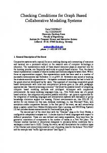
1. Introduction Biometrics based automated personal recognition are investigated extensively in the recent years [1, 2]. Some biometric features, such as the tongue [3, 4], pulse [5], iris and palm [6], etc. also can be used to automatically diagnose diseases (called medical biometrics). In the theory of palm medicine (PM) [7, 8], the palm colors, the shapes formed by the palm lines, the mounds and valleys on the palm can indicate some diseases. Especially, some special shapes formed by palm lines can reveal some chronic and malignant diseases, such as cancers. Eight special palm line shapes have been summarized for palm diagnosis [7, 8]: cross-shape (“+”), “*””), triangle-shape shape, “#”-shape, island-shape (“ (“ ”), rectangle-shape (“ ”), “ ”-shape, circle-shape (“ ”). Figure 1 shows some examples of these special shapes. However, these special shapes are described subjectively in PM. For example, the palm doctors define the
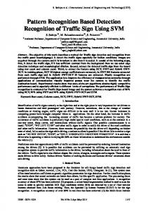
cross-shape as “the ‘+’ like shape, which is composed of two perpendicular lines, both short or one short line and the other long”. This definition is very subjective and confused, such as the term “’+’ like”, “short” and “long”. What is “+”-like? What length is defined as “long” or short? And little palm lines are strictly “perpendicular”. Therefore, it is very difficult to use these subjective and confused descriptions to extract the shapes from the palm images. Up to now, we failed to find any literature about automatically recognizing these special shapes for palm diagnosis. As the first attempt, this paper will discuss the automated cross-shape identification in palm images. Because there are some algorithms to convert the greyscale palm images to binary palm line images [9], we focus on extracting the cross-shapes from the binary palm line images. Figure 2 shows the center part of a palm image and the corresponding palm line image.
Figure 1. Some examples of the eight special shapes in PM
(a) (b) Figure 2. An example of the center part of a palm and the extracted palm line image
1 This work is supported by the National Natural Science Foundation of China (No. 60441005), the Key-Project of the 11th-Five-Year Plan of Educational Science of Hei Longjiang Province, China (No. HZG160) and the Excellent Young Teachers Program of Harbin Institute of Technology, China.
Proceedings of the Sixth International Conference on Intelligent Systems Design and Applications (ISDA'06) 0-7695-2528-8/06 $20.00 © 2006 Authorized licensed use limited to: Hong Kong Polytechnic University. Downloaded on March 29, 2009 at 22:16 from IEEE Xplore. Restrictions apply.
2. Palm Line Undirected Graph Construction
3. Cross-shape Recognition
Suppose L( x, y ) is a palm line image, in which the values of the points on the palm lines are 1 (white) while the values of other points are 0 (black) (Figure 2). Now we construct an undirected graph (called palm line undirected graph, PLUG) G = (V , E ) to represent the palm line structure, where V and E are the vertex set and the edge set respectively. The algorithm to converting the palm line image L to the PLUG G is described as below: 1) For each white point ( x, y ) in L , count the number of its neighbour white points, denoted as d ( x, y ) . 2) The vertex set V is constructed as following: V = {v1 , v 2 ,",Vn } (1) = {( x, y ) | L( x, y ) = 1 and d ( x, y ) ≠ 2} If the curvature of the palm line between two vertices is large, the point with the maximum curvature is regarded as a new vertex and added into V . And if the distance of two vertices v m , vk is smaller than a threshold, these two
We recognize the cross-shape recognition in the PLUG. According to the description of the cross-shape in PM, a cross-shape must be formed at a vertex and its degree should greater than 2. And the length of the palm lines formed the shape, the angle formed by these palm lines and the characteristics of the neighbour vertices should satisfy some conditions for a cross-shape. Consequently, we define and investigate the following four types of features for cross-shape recognition: degree feature, length feature, angle feature and the neighbour vertices feature. Let U be a collection of all vertices with degree greater than 2. We define a fuzzy set F in U as below: (3) F = {µ (v) / v} where v is a vertex with degree greater than 2 and µ (v ) is its membership function in F , which is defined as below: µ (v ) = µ1 (v) µ 2 (v) µ3 (v ) µ 4 (v) (4) where µ1 (v),", µ 4 (v ) are four components of µ (v ) , which contain the information about the degree feature, length feature, angle feature and the neighbour vertices feature, respectively. The definition of these features and the corresponding components of v are presented in the following several subsections.
vertices are merged: let v m be
vm + vk and delete v k 2
from V . 3) The edge set E is constructed as below: E = {(v m , v k } | v m , vk ∈ V , and there is a palm line segment between vm and vk , and there is no other (2) vertices on this palm line segment} Figure 3 shows some palm line images and their PLUGs.
(a)
3.1. Degree Feature The cross-shape is formed by two intersecting palm lines. Therefore, the degree of the vertex (degree feature), at which a shape is formed, should be considered when deciding the type of the shape. Obviously, when the degree feature is 4, the component v1 should be the maximum. Therefore, we can define the component µ1 (v) as below: 2 1 µ 1(v) = 1 + × ( N − 4)) 2 where N is the degree of v .
−1
(5)
3.2. Length Feature
(b) Figure 3. Some examples of the palm line images and their PLUGs.
The two palm lines formed a cross-shape are both short or one short and the other long. Therefore, we should consider the length of the palm lines forming this shape (length feature). When two palm lines intersect at v and one of them is short, the component µ 2 (v) , which reflects the length feature, should be great. Suppose v is a vertex of a PLUG G and L1 ,", Lm are the lengths of the edges connected with v , where
Proceedings of the Sixth International Conference on Intelligent Systems Design and Applications (ISDA'06) 0-7695-2528-8/06 $20.00 © 2006 Authorized licensed use limited to: Hong Kong Polytechnic University. Downloaded on March 29, 2009 at 22:16 from IEEE Xplore. Restrictions apply.
m ≥ 3 is the degree of v . When m = 3 , the topology of the edges is shown in Figure 4 (a). In this case, let L4 = L5 = 0 . When m = 4 , the topology of the edges is shown in Figure 4 (b). In this case, let L5 = 0 . And when m > 4 , let L1 , L2 , L3 , L4 be the maximum four lengths and the topology of these four edges are shown in Figure 4 (c). In this case, let L5 be the fifth maximum length. Now
we define µ 2 (v) as the following equations:
−1
4 1 + 1 × ( x − 10)) x < 10; , 5 F ( x) = 1 , 10 ≤ x ≤ 20; (6) −1 2 1 + 1 × ( x − 20)) , x > 20. 10 1 µ 2 (v ) = F (min(( L1 + L3 ), ( L2 + L4 ))) × . (7) 1 + 2 L5 −1
L2 L3
v
L3
L3
v
L1
L5
L6
v
L4
L4
L4
(a)
(b)
(c)
As the description in PM, the cross-shape is “+”-like shape, which is formed by two perpendicular lines. That is, the angles formed by the adjacent edges of the vertex (angle feature) should be near π / 2 . The angles formed at vertex v are shown in Figure 5. Let m be degree of v . When m = 3 , let θ3 = θ1 , θ 4 = θ 2 . When m > 4 , L1 , L2 , L3 , L4 are the edges with the maximum four lengths (Figure 5 (c)). Then we define µ 3 as the following equations: i =1
π 2
1
− θi
(8) 2
−1
µ 3(v ) = 1 + × γ ) π
v
θ1
θ2
v
θ1
L3
θ4
θ3
L4
θ2
v
θ1 θ4
θ3
L1
L4
(b)
(c)
3.5. Process of Cross-shape Extraction
3.3. Angle Feature
4
L2 θ2
Figure 5. The definitions of the angles formed by the edges.
L1
Figure 4. The definition of the lengths of the edges connected with vertex v .
γ =∑
2 1 µ 4(v) = 1 + × ( N1 − 4) (10) 4 where N1 is the number of the neighbour vertices with degree 1.
(a)
L2
L2 L1
lines which formed this shape are expected not to intersect with other lines in the palm. That is, the neighbour vertices of v are expected to be produced by endpoints of palm lines. Therefore, we should consider the neighbour vertices (neighbour vertices feature). Obviously, if the degree of a neighbour vertex is 1, it means that this neighbour vertex is produced by an endpoint of a palm line. Hence, we can define µ 4 as below:
(9)
3.4. Neighbour Vertices Feature According to the theory of PM, a cross-shape has better not connect with other shapes. In other words, the palm
The entire process of cross-shape extraction is given as below: 1) Use the algorithm presented in [9] to convert the greyscale palm images to binary palm line images; 2) Construct the PLUG according to the palm line image; 3) For each vertex v with degree greater than 2, use Eq. (5) – (10) to compute µ1 (v), µ 2 (v), µ3 (v), µ 4 (v) and then compute µ (v ) = µ1 (v) µ 2 (v) µ3 (v ) µ 4 (v) ; 4) If µ (v ) of a vertex is greater than a threshold, a cross-shape is extracted at this vertex (in this paper, the threshold is chosen as 0.5).
4. Experimental Results We employed the PolyU Palmprint Database to test our approach. This database contains 600 grayscale images captured from 100 different palms by a CCD-based device, 6 samples from each palm. The size of the images in the database is 384 by 284. For simplification, the central 128 by 128 part of the image was cropped, by using the preprocessing technique described in [10], to extract the cross-shapes. All cross-shapes in these images are labelled by palm diagnosis experts. About 90% cross-shapes have
Proceedings of the Sixth International Conference on Intelligent Systems Design and Applications (ISDA'06) 0-7695-2528-8/06 $20.00 © 2006 Authorized licensed use limited to: Hong Kong Polytechnic University. Downloaded on March 29, 2009 at 22:16 from IEEE Xplore. Restrictions apply.
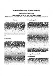
been correctly recognized and about 2% other shapes have been incorrectly recognized as the cross-shapes. Most of the errors are resulted from the errors of palm line extraction. Figure 6 shows some the experimental results. (a) is a palm line image in which all vertices with degree greater than 2 are labelled. (b) is the PLUG of the palm line image in (a) and (c) is the result of the cross-shape recognition, in which the extracted cross-shapes are circled. Table 1 lists the values of µ1 , µ 2 , µ 3 , µ 4 and µ of the labelled vertices.
5. Conclusion and Future Work Palm medicine is a convenient technique for disease diagnosis. As the first attempt to recognize shapes for palm diagnosis, we proposed an approach to identify the cross-shapes. According to the description of the crossshape in PM, four classes features have been considered in the proposed approach: degree feature, length feature, angle feature and neighbour vertices feature. A fuzzy set and its membership function have been defined according to these features. The experimental results show that the propose approach can detect the cross-shape effectively. In the future, we will investigate other special shape (such as the “*”-like shape and the island shape, etc) detection using the PLUG.
References [1] D. Zhang, Automated Biometrics–Technologies and
Systems, Kluwer Academic Publishers, 2000. (a)
(b)
(c) Figure 6. A result of the cross-shape detection: (a) palm line image; (b) PLUG; (c) the detected cross-shapes (circled). Table 1. The membership grades of the each vertex with 3 degree. µ µ1 µ2 µ3 µ4 Vertex NO. 1 0.800 1.000 0.247 0.941 0.186 2 1.000 1.000 0.722 0.941 0.679 3 1.000 0.389 0.457 0.640 0.114 4 0.800 0.693 0.332 0.640 0.119 5 1.000 0.816 0.966 0.941 0.742 6 0.800 1.000 0.287 0.640 0.147 7 0.800 0.016 0.378 0.800 0.004 8 0.800 0.179 0.443 0.941 0.059 9 1.000 0.798 0.959 1.000 0.766 10 1.000 0.350 0.975 0.800 0.273 11 1.000 0.585 0.920 0.941 0.507 12 0.800 0.933 0.278 0.800 0.166 13 0.800 0.179 0.426 0.800 0.049 14 1.000 0.828 0.929 0.941 0.724
[2] A. Jain, A. Ross and S. Prabhakar, “An introduction
to biometric recognition,” IEEE Transactions on Circuits and Systems for Video Technology 14(1), pp. 4– 20, 2004. [3] B. Pang, David Zhang and Kuanquan Wang. “The Bielliptical Deformable Contour and Its Application to Automated Tongue Segmentation in Chinese Medicine,” IEEE Transactions on Medical Imaging 24(8), pp.946–956, 2005. [4] B. Pang, K. Wang, and D. Zhang, “Tongue Image Analysis for Appendicitis Diagnosis,” Information Science 175(3), pp.160–176, 2005. [5] L. Xu, D. Zhang, and K.Q. Wang, “Wavelet-based Cascaded Adaptive Filter for Removing Baseline Drift in Pulse Waveforms,” IEEE Transactions on BME 52(11), pp.1973–1975, 2005. [6] X. Wu, L. Liu, N. Li, etc. “Automated Palm Diagnosis System,” The 2nd World Integrative Medicine Congress (WIMCO 2002), Beijing, 2002. [7] C. Wang, Diagnostics based upon Observation of Palmar Lines, Shandong Friendship Publishing House, 1996. [8] L. Li, D. Tian and C. Jiao, Details of Holographic Medicine, Chinese Medicine Technology Publisher, 2000. [9] X. Wu, D. Zhang, K. Wang, “Palm-line Extraction and Matching for Personal Authentication,” To appear in IEEE Transactions on Systems, Man, and Cybernetics, Part A, 2006. [10] D. Zhang, W. Kong, J. You, M. Wong, “Online palmprint identification,” IEEE Transactions on Pattern Analysis and Machine Intelligence 25(9), pp.1041-1050, 2003.
Proceedings of the Sixth International Conference on Intelligent Systems Design and Applications (ISDA'06) 0-7695-2528-8/06 $20.00 © 2006 Authorized licensed use limited to: Hong Kong Polytechnic University. Downloaded on March 29, 2009 at 22:16 from IEEE Xplore. Restrictions apply.