Apr 2, 2006 - graph transformation-based semantics to one of the original QVT language ... a unified view upon the software engineering process, it is ... languages are understood as instances of a single top-level meta-metamodel, the ... where MTL[A|B] is the set of transformation definitions in MTL with source meta-.
Graph Transformation Semantics for a QVT Language Arend Rensink 1 Ronald Nederpel University of Twente, Computer Science Department P.O.Box 217, 7500 AE Enschede, The Netherlands
Abstract It has been claimed by many in the graph transformation community that model transformation, as understood in the context of Model Driven Architecture, can be seen as an application of graph transformation. In this paper we substantiate this claim by giving a graph transformation-based semantics to one of the original QVT language proposals; that is, any model transformation definition in the QVT language is translated to a graph production system whose effect is to apply that model transformation. The translation has been fully implemented.
1 Introduction In order to better understand and structure the process of software engineering, the Object Management Group (OMG) has put forward the Model Driven Architecture (MDA) approach (see [22]), with as core concepts metamodelling and model transformation. The first of these is based on the insight that, in order to provide a unified view upon the software engineering process, it is necessary to organise and relate the different (visual and textual) languages used along the way, i.e., the languages in which the different design models and artefacts are written. The organisational structure proposed in MDA is the metamodelling hierarchy: there, the languages are understood as instances of a single top-level meta-metamodel, the MOF (see [20]). According to the terminology used in this context (to which we will adhere in this paper), the languages are called metamodels, and the artefacts written in those languages (including executable programs) are called models. The second core concept in MDA, model transformation, is based on the insight that many if not all of the activities in software engineering involve the creation of 1
The research described in this paper has been carried out in the context of the Duth NWO projects GROOVE (612.000.314) and GRASLAND (612.063.408).
Preprint submitted to Elsevier Preprint
2 April 2006
MOF instanceof Metamodel A instanceof
instanceof
instanceof
MTL source
A−Model
instanceof
Metamodel B target
B−Model
Transformation definition source
instanceof
instanceof
target
Transformation pair
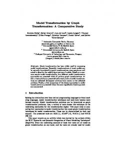
Fig. 1. Overview of MDA concepts
new models (in the sense explained above) based on existing models; and that this “creation based on” can be interpreted as a transformation of the existing models into the new. A further observation is that such transformations typically have some guiding principles that are not specific to the models, but rather can be articulated on the level of the metamodels involved. Such an “articulation of guiding principles” is called a transformation rule; a collection of transformation rules is called a transformation definition. See also [15] for a further discussion. Fig. 1 gives an overview of the resulting set of concepts. Since the MOF provides a unifying view on the metamodels and (therefore, indirectly) the models, we have available the ingredients necessary to write down transformation definitions uniformly and, once that is done, to execute them automatically. This has led the OMG some time ago to request proposals for a QVT language, where QVT stands for Query/View/Transformation (see [21]). An overview of the submissions received on this call is given in [10]. In this paper we take one of these submissions, namely the one by IBM, DSTC and CBOP [6]; we call this the Model Transformation Language (MTL) in the remainder of this paper. In terms of the ontology proposed by Czarnecki and Helsen [4], important characteristics of MTL (which determine its suitability for the approach of this paper) are that it has syntactic separation of source and target model elements, that it is unidirectional and declarative. Moreover, it supports traceability of model transformations. The essence of any language is its semantics, which captures the effect of “sentences” of the language. So, too, with MTL, where the “sentences” are transformation definitions. The effect of a transformation definition can be captured by a binary relation between the set of models residing under the source meta-model to the set of models under the target meta-model; in other words, a set of transformation pairs in the sense of Fig. 1. The semantics of MTL, therefore, is a partial mapping that assigns such binary relations to transformation definitions written in MTL. The partiality of the mapping is due to the fact that a syntactically valid
46
transformation definition may fail to be semantically correct, for instance due to inconsistencies with the source or target metamodel; in such a case it has no semantic image. Formally, the semantic mapping is a partial function [[ ]] : MTL[A|B] ⇀ 2Mod[A]×Mod[B] where MTL[A|B] is the set of transformation definitions in MTL with source metamodel A and target metamodel B, and Mod[A] (resp. Mod[B]) stands for the set of models under meta-model A (resp. B). 2 For any transformation definition D ∈ MTL[A|B], we write [[D]] for the set of transformation pairs generated by D (hence [[D]] ⊆ Mod[A] × Mod[B]). In many cases, [[D]] is in fact total and oneto-one, meaning that it can also be seen as a function Mod[A] → Mod[B]; then we write [[D]](M) ∈ Mod[B] to denote the target model obtained by applying D to the source model M ∈ Mod[A]. Unfortunately, as is the rule rather than the exception, in [6] the semantics of MTL is not defined formally but just described in natural language. This means that the basis for reasoning about, verifying and guaranteeing correctness of the model transformations, which is also mentioned in [18] as one of the success criteria for a transformation language or tool. This is the problem we set out to address in the current paper, which is based on the MSc thesis [19] by the second author. In the next section we describe the approach we have followed, of which the essence is that we translate model transformation definitions to graph production systems, which do have the desired formal basis. In Sect. 3 we show the approach on the basis of an example (actually taken from the QVT submission [6]). In Sect. 4 we evaluate the achievements and discuss some related approaches. Note that within the scope of this paper it is quite impossible to describe the actual semantics in any detail. However, see [19] for a full description.
2 Approach There is already a large body of research that supports the use of graph transformation techniques as a basis for the formal semantics of model transformation, both practical (in the sense of tools, e.g. [12,2,26,3]) and theoretical (for instance confluence and termination properties as in [17,8]). In this paper we also follow that route in order to define semantics of MTL. We will omit most of the theoretical background; see, e.g., [24] for an extensive discussion. 2.1 Principles Graph transformation works on the basis of graph production rules defined over a given universe of graphs, Graph. Finite sets of graph production rules, called graph production systems, are used as transformation specifications. Each rule R 2
As usual, 2X denotes the powerset of a set X, i.e., the set of all subsets of X.
47
describes a single-step transformation of certain graphs into others, and so defines a binary relation →R over Graph such that G →R H if and only if R turns G into H. For a production system P, the transitive closure of the union of →R for all R ∈ P then gives rise to a partial ordering over Graph, which we denote ≤P . Finally, we say that P eventually transforms G into H, denoted G ⇒P H, if G ≤P H and H is a ≤P -maximal element of Graph, i.e., it cannot be transformed further. (In other words, G ⇒P H if H is reachable from G along a path of →R -single-step transitions with R ∈ P, and H 6→R for all R ∈ P.) Let us write Rule for the universe of graph production rules. In order to define the semantics of MTL using these principles, we define the following ingredients: •
•
•
For any meta-model A, a set Graph[A] ⊆ Graph and an injective mapping gA : Mod[A] → Graph[A] to connect the MDA model world to the graph world. The mapping is in general not surjective, meaning that the inverse may be undefined. For any pair of meta-models A and B, a set of “linked graphs” Graph[A|B] ⊆ Graph that essentially consist of pairs of graphs from Graph[A] and Graph[B], together with two graph production systems, Left[A|B], Right[A|B] ⊆ Rule that “extract” the constituent graphs, such that for any G ∈ Graph[A|B], there are unique HA ∈ Graph[A] and HB ∈ Graph[B] with G ⇒Left[A|B] HA and G ⇒Right[A|B] HB . A mapping GPS: MTL[A|B] → 2Rule that yields a graph production system from an arbitrary MTL transformation definition D ∈ MTL[A|B], such that for any G ∈ Graph[A] there is a unique linked graph H ∈ Graph[A|B] that satisfies G ⇒GPS(D) H; and, moreover, for which H ⇒Left[A|B] G.
We then define, for any D ∈ MTL[A|B] and M ∈ Mod[A], [[D]](M) = gB−1 (H) where gA (M) ⇒GPS(D) G ⇒Right[A|B] H . In words, the semantics of D is defined, for an arbitrary model M ∈ Mod[A], by first mapping M to the graph gA (M) ∈ Graph[A], then transforming that to a linked graph G ∈ Graph[A|B] using the dedicated graph production system GPS(D), then extracting H ∈ Graph[B] from this combined graph, and finally converting H to a model gB−1 (H) ∈ Mod[B]. Due to the fact (noted above) that gB may fail to be surjective, in general it is possible that gB−1(H) is not defined, in which case neither is [[D]](M). We currently have no way to detect or ensure statically which D give rise to a total function [[D]]. 2.2 Implementation The steps described above have all been implemented, resulting in the tool chain depicted in Fig. 2, where boxes are products and ovals represent processes steps. The fat boxes are the inputs and output products of the chain; the thin ones are auxiliary products that are both produced and consumed in the course of the transformation. The grey ovals were implemented in the course of this research; the 48
1 Metamodel A
1 Metamodel B
3 D ∈ MTL[A|B]
2 M ∈ Mod[A]
5
4 model-to-graph
6
translate
apply
4 graph-to-model
Right[A|B]
GPS(D)
gA (M )
−1 gB (H)
construct
G ∈ Graph[A|B]
H ∈ Graph[B]
apply
Fig. 2. Transformation tool chain
white ovals, labelled “apply”, stand for the application of a graph production system using a pre-existing tool. We will now discuss the individual steps and some relevant design decisions. (1) In general the metamodels are, as shown in Fig. 1, instances of the MOF. However, the MOF is itself still quite extensive; for the purpose of this paper we concentrated on a subset, depicted in Fig. 3. For the purpose of this work the metamodels were created as class diagrams and stored in (a version of) XMI using Borland Together. (2) The models, likewise, were created (as object diagrams) and stored in XMI using Together. Note that we need to have the models as instances of their metamodels, i.e., the instantiation relation depicted in Fig. 1 needs to be clear. (3) The concrete and abstract syntax of the language MTL are defined in [6] by an EBNF grammar, resp. an abstract syntax meta-model. An example is given there also, which we use as well in the next section. Unfortunately, here a problem exists, in that the example cannot be parsed according to the grammar and cannot be matched to the abstract syntax; nor do the concrete and abstract ModelElement name: String
GeneralizableElement isAbstract: boolean supertype
Attribute type
Classifier
from AssociationEnd type
Association to
Class attributes
Fig. 3. Fragment of the MOF used in this paper
49
syntax seem to be consistent. In [19] we report a host of problems and propose solutions; in the remainder of this paper we follow [19] in actually working from the proposed solutions. For the purpose of this paper we just show the main rule of the grammar, which defines a transformation rule: trule ::= "RULE" rname formals ( relatedRules )* "FORALL" ranges ( "WHERE" conjunct )? "MAKE" targets ( "LINKING" trackingUses )? SEMI
The lowercase identifiers are further nonterminals; the quoted strings and uppercase identifier are terminals of the concrete syntax; the rest is EBNF syntax. • The rname is the rule name; formals are formal names used in the FORALL and MAKE parts; and the relatedRules provide a reuse (i.e., inheritance) mechanism between rules. • The FORALL part specifies where the rule applies, i.e., what needs to be matched in the source model. In the ranges more formal names are introduced, referring either to the elements in the source model that are to be matched, or to elements of the target model that were already created. The WHERE clause essentially contains equations based on these names and connected model elements; these serve to constrain the local structure of the model where the rule is to be applied. • the MAKE part specifies what needs to be created in the target model whenever a match for the FORALL part is provided: the targets part lists new model elements and their relation to the existing elements matched in the FORALL. The LINKING clause can be used to specify traceability information, in the form of links between elements of the source model and the newly created target elements. (4) In this step we translate models to graphs and back. For the purpose of the current paper, we have chosen a very “poor” graph formalism: the graphs in Graph just consist of unlabelled nodes and labelled directed binary edges; parallel edges, attributes, hierarchy and typing are not included. This is the type of graphs supported by the GROOVE tool [23]; the choice was determined pragmatically by the local availability of the tool. It should be noted that we do not consider the choice of graph formalism to be a relevant part of the research reported in this paper; in Sect. 4 we discuss alternatives. In the representation of models as graphs, embodied by the functions gA discussed above, we have had to make some representation choices. In particular, we chose to represent MOF Class instances as nodes inscribed with the names of their direct types, bidirectional Associations as pairs of labelled edges in opposite directions, and Attributes as single edges. Supertypes are not represented in the models; instead, any rule dealing with a metamodel type has to be duplicated for all (combinations of) subtypes.
50
(5) Essentially, every trule of the transformation definition is turned into a graph production rule R. Its left hand side is generated from the FORALL clause: each formal name in trule gives rise to a graph node, and the WHERE clause is translated to edges between those nodes. R’s right hand side is a supergraph of the left hand side (so nothing is deleted), and contains the following further elements (which will therefore be created upon rule application): (a) A node labelled LINK, with edges to those nodes that match source and target model elements involved in the rule, as well to another new node labelled with the rule name. This “rule node” indicates that the rule has been applied here. A correspondig negative application condition is also added to the rule, to prevent it from being applied more than once. (b) Nodes and edges corresponding to the target model elements named in the MAKE part. (c) Nodes for each of the elements named in trackingUses, to model the LINKING clause, as well as edges connecting to the relevant source and target model nodes. These nodes and edges eventually make up the linking structure in Graph[A|B]. By using this setup, the rules in GPS(D) only add elements to the graphs, rather than doing in-place model transformation. This makes it quite easy to mimic each MTL rule. As a consequence, the resulting graph will be a combination of the source and target graphs linked together by LINK and trackingUse nodes and their corresponding edges. (6) The Left[A|B]- and Right[A|B]-production systems extract the A- and Binstance graphs from the linked graph produced by the rules discussed above. This is done by stripping away the nodes and edges introduced by the (a) and (c)-parts of the rules, as described in (5) above, as well as the elements of the target (for Left) resp. source model (for Right) that they link to.
3 Example To illustrate the steps described in the previous section, we take an example from [6] of UML-to-Java model transformation. Another example is presented in [19]. Fig. 4 shows the (hugely simplified) UML metamodel used in this example. Transforming UML to Java is not very challenging, since the models are already very close: mainly it is a matter of changing the metamodel names, for instance from UMLClass to JavaClass. The most interesting part of the transformation is the required addition of a constructor, which is mandatory according to the Java metamodel used. This transformation is specified by the following couple of rules in the MTL transformation definition: RULE UmlClassifierToJavaClass(uc,jc) FORALL UMLClassifier uc MAKE JavaClass jc,
51
UMLModelElement name: String
UMLClassifier
UMLInterface
feature owner
UMLClass
UMLFeature
UMLAttribute
UMLParameter parameter
UMLOperation behaviouralFeature
Fig. 4. Simplified UML metamodel jc.name = uc.name LINKING JavaClassFromUMLClassifier jcuc WITH jcuc.javaClass = jc, jcuc.umlClassifier = uc; RULE UmlClassToJavaClass(uc,jc) EXTENDS UmlClassifierToJavaClass(uc,jc) FORALL UmlClass uc MAKE JavaMethod m, m.name = uc.name, jc.constructor = m LINKING JavaConsFromUMLClass consFromClass WITH consFromClass.constructor = m, consFromClass.umlClass = uc;
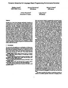
The second of these rules give rise to the graph production rule displayed in Fig. 5 (in the GROOVE format). The fat grey nodes and edges (green, in a coloured representation) are to be added, the even fatter dashed part (red) is the negative condition that prevents the rule from being applied twice. The rule is layed out so that source model nodes are on the left, auxiliary nodes (parts (a) and (c) in step (5) described above) are in the middle and target nodes are on the right of the figure. Other rules, such as the one for transforming the attributes, actually use the trackingUse information introduced by the above rule to link the new elements to the correct nodes. Finally, Fig. 6 shows an example source and target graph. We omit the corresponding models and the linked graph for lack of space.
4 Conclusion We briefly evaluate the work presented in this paper, suggest some possible extensions and discuss related work. Evaluation. The contribution of the research reported in this paper is not theoretical but rather in the nature of a proof-of-concept: none of the steps implemented 52
Fig. 5. Transformation rule (in GROOVE) for a UMLClass, introducing a constructor
is new, rather the novelty lies in having actually carried through all of them consistently, which among other things involves taking many small design decisions. Based on this exercise we can confirm some widespread beliefs. •
•
Even using a very “poor” graph model, it is possible to give a semantics to a sizeable fragment of a full-blown model transformation language; Defining a semantics in this way is a useful step, because it helps to uncover flaws and ambiguities in the language definition;
The language studied in this paper, as described in the official submission [6] to the QVT request for proposals, indeed contained many flaws and ambiguities: the full thesis [19] reports 11 issues in the grammar that either prevent the example in the submission itself from being parsed or give rise to parsable texts that are clearly unintended, and 7 issues in the abstract syntax metamodel that are either poorly documented or inconsistent with the grammar and the example. Possible extensions and future work. There are several directions in which this work should be extended and improved before we can claim to have a full MTL
source graph
target graph
Fig. 6. Example source and target graphs
53
semantics. •
•
•
•
•
The work reported in this paper is pragmatic rather than theoretic. In particular, the mapping GPS discussed in Sect. 2, which maps MTL transformation definitions to graph production systems, has not been worked out in full formal detail; instead it has been “defined” in the form of a tool implementation. The fragment of the MOF that we have treated (see Fig. 3) should be extended. For instance, one of the more prominent features currently missing is association ordering. However, we believe that this requires no fundamental change to the framework: one just has to extend the model-to-graph and graph-to-model conversions with a suitable graph representation of the order, and take this into account in the transformation rules. MTL rule paramaterisation and generalisation are not supported. Although this can be mimicked through syntactically copying and substituting the rules, that is a very poor solution which, for one thing, blows up the number of rules. To cope with this in a more fundamental way, one can use for instance node type inheritance in the graph transformation formalism, as proposed in [1,27]. Attributes are supported only poorly in the graph transformation formalism we have used (however, see [14] for initial ideas on improving this). Choosing a category of graphs (Graph) that is closer to the category of models (Mod), such as attributed graphs and the transformation tool AGG [9,5], would improve the simplicity of both the function gA that maps the model space into the graph space, and the function GPS that defines the actual graph production systems. The QVT proposal on which this research was based has now been subsumed by the actual QVT standard. A future iteration of this work should therefore be aimed at the actual standard.
Related work. Although there has been a lot of research on using graph transformation for model transformation, some of which we have reported in Sect. 2, we have not seen the question studied in this paper, namely to give a graph transformation semantics to a pre-existing model transformation language, addressed elsewhere. Instead, precisely the inverse trajectory has been followed in [11], where model transformations specified originally in a graph transformation formalism (viz., FuJaBA) are translated to the language MTL that we have also studied in this paper, after which they are interpreted by the tool Tefkat [7]. Another source of related work is the Triple Graph Grammar approach (see [25,16,11]), which is an alternative basis for defining model transformation semantics compared to the “simple” graph transformations we have used. Triple graph grammars have the advantage of offering a more fundamental solution to the problem of linking source and target graph, which we have had to solve by introducing an ad hoc graph encoding. Acknowledgement. We wish to thank Klaas van den Berg, who co-supervised this work and without whose contribution it would never have attained its current form.
54
References [1] Bardohl, R., H. Ehrig, J. de Lara and G. Taentzer, Integrating meta-modelling aspects with graph transformation for efficient visual language definition and model manipulation, in: M. Wermelinger and T. Margaria-Steffen, editors, Fundamental Approaches to Software Engineering (FASE), LNCS 2984 (2004), pp. 214–228. [2] Burmester, S., H. Giese, J. Niere, M. Tichy, J. Wadsack, R. Wagner, L. Wendehals and A. Z¨undorf, Tool integration at the meta-model level: The FuJaBA approach, Int’l Journal on Software Tools for Technology Transfer 6 (2004), pp. 203–218. [3] Csert´an, G., G. Huszerl, I. Majzik, Z. Pap, A. Pataricza and D. Varr´o, VIATRA — visual automated transformations for formal verification and validation of UML models, in: Int’l Conference on Automated Software Engineering (ASE) (2002), pp. 267–270. [4] Czarnecki, K. and S. Helsen, Classification of model transformation approaches, in: OOPSLA 2003 Workshop on Generative Techniques in the Context of Model-Driven Architectures, 2003. [5] de Lara, J. and G. Taentzer, Automated model transformation and its validation with Atom 3 and AGG, in: A. Blackwell, K. Marriott and A. Shimojima, editors, DIAGRAMS’2004, LNAI 2900 (2004), pp. 182–198. [6] DSTC, IBM and CBOP, MOF Query/Views/Transformations, second revised submission, OMG Document ad/2004-01-06, Object Management Group (2004). [7] DSTC QVT Team, Tefkat tutorial, See www.dstc.edu.au. [8] Ehrig, H., K. Ehrig, J. de Lara, G. Taentzer, D. Varr´o and S. Varr´o-Gyapay, Termination criteria for model transformation, in: M. Cerioli, editor, Fundamental Approaches to Software Engineering (FASE), LNCS 3442 (2005), pp. 49–63. [9] Ermel, C., M. Rudolf and G. Taentzer, The AGG approach: Language and environment, in: H. Ehrig, G. Engels, H.-J. Kreowski and G. Rozenberg, editors, Handbook of Graph Grammars and Computing by Graph Transformation, Volume II: Applications, Languages and Tools, World Scientific, Singapore, 1999 pp. 551–604. [10] Gardner, T., C. Griffin, J. Koehler and R. Hauser, A review of OMG MOF 2.0 Query/Views/Transformations submissions and recommendations towards the final standard, in: First International Workshop on Metamodelling for MDA, 2003. [11] Grunske, L., L. Geiger and M. Lawley, A graphical specification of model transformations with triple graph grammars, in: A. Hartman and D. Kreische, editors, Model Driven Acritecture — Foundations and Applications (ECMDA), LNCS 3748 (2005), pp. 284–298. [12] Kalnins, A., J. Barzdins and E. Celms, Model transformation language MOLA, in: U. Aßmann, M. Aksit and A. Rensink, editors, Model Driven Architecture, LNCS 3599 (2005), pp. 62–76.
55
[13] Karsai, G. and G. Taentzer, editors, “International Workshop on Graph and Model Transformation (GRAMOT),” 2005, to appear. [14] Kastenberg, H., Toward attributed graphs in GROOVE (work in progress), in: R. Heckel, A. Rensink and B. K¨onig, editors, Graph Tranformation for Verification and Concurrency, ENTCS, 2005, to appear. [15] Kleppe, A., J. Warmer and W. Bast, “MDA Explained, the Model Driven Architecture: Practise and Promise,” Addison-Wesley, 2003. [16] Koenigs, A. and A. Sch¨urr, Multi-domain integration with MOF and extended Triple Graph Grammars, in: J. Bezivin and R. Heckel, editors, Language Engineering for Model-Driven Software Development, number 04101 in Dagstuhl Seminar Proceedings (2005). [17] Lambers, L., H. Ehrig and F. Orejas, Efficient detection of conflicts in graph-based model transformation, in: Karsai and Taentzer [13], to appear. [18] Mens, T. and P. Van Gorp, A taxonomy of model transformation, in: Karsai and Taentzer [13], to appear. [19] Nederpel, R., “A QVT model transformation language represented by graph production systems,” Master’s thesis, Department of Computer Science, University of Twente (2005), see http://www.cs.utwente.nl/˜rensink/papers/nederpel2005.pdf. [20] OMG, Meta Object Facility (MOF) specification, version 1.4, OMG Document formal/2002-04-03, Object Management Group (2002). [21] OMG, MOF 2.0 Query/View/Transformations RFP, version 1.1, OMG Document ad/2002-04-10, Object Management Group (2002). [22] OMG, MDA guide, version 1.0.1, OMG Document omg/2003-06-01, Object Management Group (2003). [23] Rensink, A., The GROOVE simulator: A tool for state space generation, in: J. Pfalz, M. Nagl and B. B¨ohlen, editors, Applications of Graph Transformations with Industrial Relevance (AGTIVE), LNCS 3062 (2004), pp. 479–485. [24] Rozenberg, G., editor, “Handbook of Graph Grammars and Computing by Graph Transformation, Volume I: Foundations,” World Scientific, Singapore, 1997. [25] Sch¨urr, A., Specification of graph translators with triple graph grammars., in: E. W. Mayr, G. Schmidt and G. Tinhofer, editors, Graph-Theoretic Concepts in Computer Science, LNCS 903 (1995), pp. 151–163. [26] Sprinkle, J., A. Agrawal, T. Levendovszky, F. Shi and G. Karsai, Domain model translation using graph transformations, in: International Conference and Workshop on the Engineering of Computer-Based Systems (ECBS) (2003), pp. 159–168. [27] Taentzer, G. and A. Rensink, Ensuring structural constraints in graph-based models with type inheritance, in: M. Cerioli, editor, Fundamental Approaches to Software Engineering (FASE), LNCS 3442 (2005), pp. 64–79.
56