International Journal of Computing and Digital Systems ISSN (2210-142X) Int. J. Com. Dig. Sys. 5, No.2 (March-2016) http://dx.doi.org/10.12785/ijcds/050205
Group based Shortest Path Routing Algorithm for Hierarchical Cross Connected Recursive Networks (HCCR) Omair Inam1, Sharifa Al Khanjari2 and Wim Vanderbauwhede2 1
Electrical Engineering Department, COMSATS Institute of Information Technology, Islamabad, Pakistan 2 School of Computing Science, University of Glasgow, Glasgow, UK
Received 20 July 2015, Revised 28 December 2015, Accepted 17 January 2016, Published 1 March 2016 Abstract: Interconnection networks play a significant role in efficient on-chip communication for multicore systems. This paper introduces a new interconnection topology called the Hierarchical Cross Connected Recursive network (HCCR) and a Group-based Shortest Path Routing algorithm (GSR) for the HCCR. Network properties of HCCR are compared with Spidergon, THIN, 2-D Mesh and Hypercube. It is shown that the proposed topology offers a high degree of regularity, scalability, and symmetry with a reduced number of links, small diameter and low node degree. A unique address encoding scheme is proposed for hierarchical graphical representation of HCCR networks, based on which the GSR was developed. . The proposed addressing scheme divides the HCCR network into logical groups of same as well as different sizes. Packets move towards receiver using local or global routing. Simulations are performed to find all the possible shortest paths with GSR in HCCR networks (up to 1024 nodes). All the shortest ( ) paths produced by GSR are verified against Dijkstra‟s algorithm. The GSR for k-level HCCR ( ) with nodes, requires ( ) time in the worst case to determine the next node along the shortest path. Average distance and frequency of hop counts of HCCR networks are investigated using GSR. The results are compared with average distance of 2-D Mesh. Experimental results show that with a network size of 1024 nodes, there is only a 7.7% increase in the average distance of HCCR in comparison to 2-D Mesh. However have fewer paths with high hop count in comparison to 2-D Mesh. Keywords: Shortest path routing Algorihtm, Network-on-Chip,Heirarchical Interconnects, manycores
1. INTRODUCTION Over the last two decades, advancements in deep submicron technology have made it possible to incorporate multimillion transistors into complex, power efficient, reliable and low cost embedded systems. Nowadays, electronic consumer products can be realised as integrated set of electronic devices capable of performing variety of functions. In order to exploit parallel computing, chip manufacturers include multiple CPU cores on a single chip i.e. multi-core or chip multiprocessor (CMP) architectures [1]. CMP has become a popular choice compared to complex, monolithic, power hungry unicore CPUs. For example Intel core 2 duos, Intel core i7, AMD Opteron, IBM Cell processor are popular CMPs. Tilera Crop has unveiled Tile Gx100 with 100-core general purpose processor. The evolution of CMP with many cores puts enormous strain on the underlying on-chip communication architecture. A single shared bus is the simplest on-chip communication architecture. Traditional bus-based and crossbar-based communication
architectures such as ARM‟s AMBA, AHB, AXI, ST Microelectronics‟ STBus, IBM‟s Core-connect, and the Sonics Silicon Backplane, may provide efficient, cost effective solution and well-defined communication protocol to add new cores into the system. But increasing number of cores on a centralized interconnect architectures can worsen arbitration delay, latency, reachable clock frequency and power consumption due to the sharing of aggregate bandwidth, resulting in limited scalability. Network-on-Chip (NoC) has emerged as a promising candidate for efficient on-chip communication with distributed scheduling and routing. NoC provides high-throughput, low-latency, congestion-aware scheduling, better scalability and reusability in multicore systems. NoC is mainly characterised by its topology, routing algorithm, control flow techniques and router microarchitecture. The two fundamental design challenges for any NoC in terms of overall system cost and performance are topology and routing algorithm. Topology defines the physical layout between the nodes and communication links inside the network. The role of routing algorithm is to route a packet towards its receiver, using minimal or non-minimal paths inside the network.
Email address:
[email protected],
[email protected],
[email protected]
http://journals.uob.edu.bh
148
Omair Inam, et. al.: Group based Shortest Path Routing Algorithm …
The specific route chosen by an algorithm determines the hop-count, which has profound impact on the system‟s performance in terms of throughput and latency. Routing algorithms for NoCs are classified as minimal and nonminimal routing. The former always chooses the shortest paths and latter may use longer paths for communication. This paper presents a new on-chip interconnection architecture i.e. Hierarchical Cross Connected Recursive network (HCCR) along with a novel group-based shortest path routing algorithm (GSR). HCCR is derived from the WK-recursive topology [2], with small node degree and reduced number of links. The proposed network is simple, hierarchical, symmetrical and scalable interconnection architecture which makes it suitable for communication in parallel/distributed networks. Our main contributions are: 1) giving a unified representation of HCCR with unique address encoding scheme and provide a solution to find shortest path in HCCR; 2) validating the results of proposed algorithm with Dijkstra‟s algorithm [3]; 3) demonstrating that HCCR can provide low cost communication architecture due to reduced number of links and small node degree; 4) studying the average distance and frequency of hop count in HCCR (up to 1024 nodes) and assess its performance for many core systems. To perform all above tasks, a SystemC based communication framework is developed to implement HCCR (up to 1024 cores) along with the proposed routing algorithm. Average distance and frequency of hop counts in HCCR and 2-D Mesh are evaluated by using GSR and XY algorithm respectively. Simulation results show that for a network size of 1024 nodes, HCCR has a smaller average distance as compared to Spidergon and THIN networks. There is only a 7.7% increase in the average distance of HCCR in comparison to 2-D Mesh for a network size of 1024 nodes. However HCCR has fewer very long paths in comparison to 2-D Mesh and scales better with the size of network. These properties of HCCR make it a good choice for efficient communication in many core systems, at low cost. In the worst case, for k( ) level HCCR ( ) with nodes, proposed algorithm requires ( ) time for k > 0 to determine the next node along the shortest path. The remainder of this paper is organized as follows: In the next section related work on the NoC topologies and shortest path routing algorithms for hierarchical networks is discussed. In section III, architecture of HCCR networks is explained. In Section IV, network properties of HCCR are defined. In Section V, hierarchical address encoding scheme is presented for shortest path routing. Section VI discusses the address mapping scheme for shortest path routing in HCCR. Section VII explains the working of GSR for k-level HCCR ( ). In Section VIII, simulation results are illustrated. Section XI draws the conclusion and discusses future recommendation.
2. RELATED WORK A. NoC Toplogies There have been many architectural and theoretical studies on NoCs topologies. Direct topologies such as rings [4] are cost-effective, but deliver relatively poor performance, especially as the number of connected cores increases. Reference [5] proposed Tornado NoC, a scalable ring based architecture for many core systems. Proteo [6] introduced hierarchical interconnect topology with global bidirectional ring, connecting several sub networks. Reference [7] presented a hierarchical ring topology, focusing on reducing energy consumption of interconnect using dynamic clock throttling. On the other hand, among higher connectivity topologies, 2-D mesh [8] has been the most popular topology. However in case of larger networks, 2-D meshes are susceptible to large hop counts over a long distance. Reference [9] chose hybrid network consisting of hierarchical rings in the mesh, with aim to reduce congestion and reduce latency. Torus has been introduced to further reduce the 2-D mesh diameter by adding wrap around links [8]. A hierarchical torus has been studied to get better performance than torus in case of localized traffic distribution [10]. CMESH has been introduced [11] with an aim to reduce the diameter and number of routers in 2-D mesh. However CMESH requires long links and higher degree routers than 2DMesh. A WK-recursive hierarchical network has been presented [2], offering high degree of regularity, scalability, and symmetry, which makes it suitable for manufacture using VLSI technology. There are very little efforts made for the low degree network such as Octagon [12] and Spidergon [13] proposed by ST Microelectronics. In [24] Spidergon-Donut (SD) network is proposed. SD extends Spidergon to the second dimension with 1024 nodes. Triple-based Hierarchical Interconnection Network (THIN) [14] focused on decreasing node degree, reducing links and shortening diameter. THIN is preferable to construct interconnection network when the network size is not too large. B. Shortest Path Routing Algorithms for hierarchical interconnection network An extensive research has been conducted on the shortest path routing algorithm for hierarchical interconnection networks. Reference [15] presented an algorithm for shortest path routing on crossed cube network with time complexity ( ). Optimal dynamic two terminal message routing algorithm has been ) networks for the presented for k-circulant ( restricted shortest path in ( ) time [16]. Shortest path routing is proposed for WK-recursive incomplete networks with ( ) time preprocessing. Where d > 1 is the size of basic building block and t 1 is the level of expansion [17]. This algorithm takes ( ) time for each intermediate node to determine the next node along the shortest path. Reference [18] proposed shortest path routing algorithm to investigate the properties of Hyper de
http://journals.uob.edu.bh
Int. J. Com. Dig. Sys. 5, N. 2, 147-159 (March-2016) Brujin network. Shortest path oblivious routing algorithm is proposed for n-level fully connected networks (FCCNs) with N = nodes, at the cost of O(N) parallel offline steps and list of N stored at each node [19]. This algorithm requires O(n) time at each related node. Reference [20] presented a routing algorithm that finds n disjoint shortest paths in n-dimensional hypercube in ( ). Shortest path routing algorithm is proposed for Multi-Mesh of Trees on processor network [21]. This algorithm requires 12 log n + 1 time in the worst case. Distributed deterministic routing algorithm (DDRA) [22] for THIN is proposed, but it is not the shortest path. The Min-DDRA [23] is proposed to further improve DDRA to obtain the shortest path. To avoid processing at each intermediate node, source routing is opted [24] using SPORT for the shortest path calculations in THIN network. 3. TOPOLOGY AND CONSTRUCTION OF HCCR In this section, following definitions are introduced to explain the construction of the proposed topology: Definition 1. The HCCR network H is represented by strongly connected directed multigraph ( ), where vertex V represents the set of cores and C represents the set of communication channels. For k-level HCCR network ( ), number of nodes (N) are defined as follows, where k ≥ 0 (
)
(1)
Definition 2. Fig.1 (a) shows the basic module consisting of four nodes, is used to construct the level 0 HCCR network ( ). Any part of the HCCR network, in which four basic modules are connected as shown in Fig 1 (b) is referred as “local block” and denoted as Definition 3. As shown in Fig.1 (c), K Level HCCR ( ) is constructed with four recursive HCCR networks, where k > 0. e.g. Fig.2 (a) shows 2 Level HCCR( ), which is constructed using four recursive 1 Level HCCRs( ). There are 16 local blocks ( ) and 256 nodes in HCCR.
149
(a)
(b)
Figure 2. a) 2 Level HCCR ( ); b) Link disciption
Definition 4. In three types of links are used to connect any node with its neighbours and are labeled as „X-links‟ (along x-axis), „Y-links‟ (along y-axis) and „B‟ as shown in the Fig. 2b. B is called “bridge link” which joins one basic module to another basic module in HCCR Definition 5. In HCCR , Three ports (portx, porty and portb) are defined at each node corresponding to appropriate link. These ports determine the link on which packet will be trasmitted. 4. NETWORK PROPERTIES OF HCCR In this section, principal properties of HCCR are defined to characterize HCCR; node degree, number of links and diameter. Later in the section, properties of HCCR are compared with Spidergon, THIN, 2-D Mesh and Hypercube. Properties of HCCR networks are defined as follows. Definition 6. Given a vertex i of a graph G, the number of channels connecting any node to its neighbors is called the degree and denoted by . The maximum degree of all nodes in G is called network degree and is denoted by d. by definition. (
)
denote the network degree of (2) Definition 7. denotes the number of links in HCCR and represented by (3). Where k is the level and N represents the number of nodes in HCCR. ( ×
(a)
(b) Figure 1. a) Basic Module of HCCR; (b)
(c)
(
)
(
)
)
(3)
Definition 8. The maximum number of edges in graph G among the all shortest paths in a network is called the diameter. Let ( ) denotes the diameter in in and is represented by (4).
; (c) ( )
√
( (
(
)
(
)
√
) )
(4)
http://journals.uob.edu.bh
150
Omair Inam, et. al.: Group based Shortest Path Routing Algorithm …
Definition 9. The average distance is the sum of all shortest paths between any two nodes in the network divided by the total number of shortest paths available in the network. Average distance of HCCR is investigated using GSR and discussed in the section VIII. A network‟s theoretical cost is usually determined by the number of links, number of routers, wire density, number of interfaces and VLSI layout area. Networks with lower degree are likely to have less communication complexity of the router, including wire congestion in the physical layout. Moreover with constant nodes degree, independent of the network size, the network is more modular and may operate at higher frequency as compared to high radix networks. For all switching strategies, a small network diameter improves network contention (in buffer and edges) and reduces propagation delay in point-point communication. Table 1 compares the network properties of the HCCR with Spidergon, THIN, 2-D mesh and Hypercube. Fig. 3, 4 and 5 compare the links and communication complexity of five different networks with different sizes, node degree and diameters. Fig. 3 illustrates that HCCR network not only out performs low degree networks such as Spidergon and THIN, in terms of diameter, but also outperforms 2-D mesh. It is due to the fact that HCCR has better scalability and modularity with small node degree. Fig. 3 and Fig. 4 show that despite having a low diameter over large network size, Hypercube becomes complex structure due to more number of links and variable node degree. A major drawback of Hypercube-based networks is that they lack expansibility. As their size grows, the number of ports gives an upper bound on their expansion. On the other hand HCCR have the fewest number of links when compared to 2-D Mesh and Hypercube (Fig. 4). A network with this property gains an advantage of easy implementation and low cost. As discussed earlier in the case of Hypercube, increasing network degree can reduce the diameter but may give rise to implementation complexity. We present a normalized diameter (diameter x degree), to study the tradeoff between node degree and diameter. Both parameters determine the overall system‟s cost and performance. Fig. 5 shows that the HCCR has the lowest normalize diameter and a show promising tradeoff between cost and performance for many core systems. 5. HIERARCHICAL ADDRESS ENCODING SCHEME FOR HCCR This section presents a novel hierarchical addressing scheme to accurately locate any node in . The scheme gives a unified representation to HCCR and provides the reference point to find possible shortest paths in the network. The proposed addressing scheme divides the HCCR network into logical groups of same as well as different sizes. Packets are routed between logical groups by using local and global addresses of sender and receiver. The address mapping and GSR is discussed in
section VI and VII. All the nodes in HCCR are grouped and addressed according to rules defined as follows. A. Local Address According to the definition 3, may consist of one or more . All the nodes in have local addresses. Local address of any node is used for local communication between any sender-receiver pair inside . Local address remains same and independent of size of network (Fig. 6). This gives a unified representation to all nodes TABLE 1. COMPARISON OF TOPOLOGY PROPERTIES Types of network
Network
Number
degree
of links
Spidergon
3
THIN
3
(
HCCR
3
(
2-D mesh
4
Diameter
( )
(
⌈ ⌉ ) )
(
(
)
√ )
)
√ (√
)
Hypercube
Figure 3. Diameter vs Network Size.
Figure 4. Links vs Network Size.
http://journals.uob.edu.bh
Int. J. Com. Dig. Sys. 5, N. 2, 147-159 (March-2016)
151
Definition 12. Let ( ) denote the position vector of node in 0 where 0 and 0 . and are referred as local index of node n in x and y dimension respectively Local index of node remains same inside and independent of the position of in HCCR.
Figure 5. Normalize diameter vs Network Size.
with same local addresses in . Local address of any node in is represented by 4 bits. Fig. 6 shows the local address of node with local ID = 01 and local group ID= 11. Following are the definitions for local ID and local group ID: Definition 10. Fig. 6 shows, all nodes inside are arranged in four distinct groups called “local groups”. Each local group consists of four nodes having unique local IDs. If L defines the set of 4 local groups in then *
L
+
* 00 0
0
+ (5)
Where , , and are local groups IDs for set of four nodes in . Local group ID of any node is represented by 2 bits and independent of network size (Fig. 6). Definition 11. If L defines the set of 4 unique local IDs in each local group then.
*
00
0
0
+
*00 0
0
+. (6)
Where 00 0 are local IDs of each 0 and node. local ID of each node is represented by 2 bits (Fig. 6). B. Local index In order to identify the position of any node inside “local index” is defined as follows.
Figure 6. Address enconding in
C. Global Addresses “Global address” are the logical addresses which are used for the communication between sender-receiver pair outside in where 0 . In Fig. 7 for global representation of any node, four symmetrical quadrants (Q1, Q2, Q3, and Q4) are introduced corresponding to four global groups. All four quadrants have only positive x and y axis. The size of global groups or quadrant depends on the level of communication (Lcom) between sender and receiver. Any node can be addressed by its “Global group ID” and represented as G (i, Lcom), where i denotes the quadrant number and 0 , and Lcom denotes the level of communication between sender and receiver. Hence global group ID of any node depends on the position of in . In Fig. 7 Sender (S1) belongs to Q3 of HCCR and receiver (R1) belongs to Q1 of HCCR. Therefore the Lcom between S1 and R1 is 2 i.e. (Lcom = 2). In this case global group IDs of S1 and R1 are ( ) and ( ) respectively. In Fig. 7, sender (S2) belongs to Q0 of HCCR and receiver (R2) belongs to Q3 of HCCR. Lcom between S2 and R2 is 1. Global group IDs of sender and receiver s are (0 ) and ( ) respectively. D. Global index In order to identify the position of any node outside side “global index” is defined as follows. Definition 13. Let ( ) denote the position vector of node g in , where 0 0 and k > 0. and are referred as global index of node g in x and y dimension respectively. This definition shows that global index dependents on the size of HCCR network.
HCCR.
http://journals.uob.edu.bh
152
Omair Inam, et. al.: Group based Shortest Path Routing Algorithm … G(2,Lcom) → G(0,Lcom) P23 = G(2,Lcom) → G(3,Lcom) , P32 = G(3,Lcom) → G(2,Lcom) , P10 = G(1,Lcom) → G(0,Lcom) and P01 = G(0,Lcom) → G(1,Lcom).
Figure 8. Up-Down and Diagonal Communication patterns in Figure 7. Global groups IDs in
HCCR.
6. ADDRESS MAPPING FOR SHORTEST PATH ROUTING ALGORITHM This section describes the unique address mapping scheme for where 0 , based on the address encoding scheme discussed in previous section. This scheme maps every sender with fixed number. These fixed numbers are used as the reference point to find the shortest path and remain fixed for any size of HCCR network. The generation of fixed numbers depends on the communication pattern that exists between sender and receiver with different global group IDs. Fig. 8 illustrates the two “basic communication patterns” in HCCR networks i.e. “up-down communication” and “diagonal communication”. Fig. 8 shows that for communication between any sender and receiver with global group ID G(3,Lcom) and G(1,Lcom) in , belongs to up-down communication and referred to as G(3,Lcom) → G(1,Lcom), whereas communication between sender and receiver with global group ID G(3,Lcom) and G(0,Lcom), belongs to diagonal communication and referred as G(3,Lcom) → G(0,Lcom). It can be seen in Fig. 8 that the topology is symmetrical along the horizontal, vertical as well as the diagonal axes. Therefore all the existing communication patterns in the network are the mirror of G(3,Lcom) → G(1,Lcom) or G(3,Lcom) → G(0,Lcom). In proposed algorithm G(3,Lcom) → G(1,Lcom) and G(3,Lcom) → G(0,Lcom) are used as “reference communication patterns” for all other patterns, to find the shortest path in HCCR for k > 0. Definition 14. If Pupdown defines the set of up-down communication patterns in for k > 0then Pupdown = { P3-1, P1-3, P2-0, P0-2, P2-3, P3-2, P1-0, P0-1 }. (7) Where, P3-1 = G(3,Lcom) → G(1,Lcom), P1-2 = G(1, Lcom) → G(3, Lcom), P0-2 = G(0, Lcom) → G(2, Lcom) , P20 =
Definition 15. Pdiagonal defines the set of diagonal communication patterns in for k > 0 Pdiagonal = { P3-0, P0-3, P1-2, P2-1 }.
(8)
Where, P3-0 = G(3,k) → G(0,Lcom), P0-3 = G(0,Lcom) → G(3,Lcom), P1-2 = G(1,Lcom) → G(2,Lcom) , P21 = G(2,Lcom) → G(1,Lcom). Following subsections explain the address mapping techniques and the generation of fixed numbers in case of basic communication patterns i.e. up-down and diagonal communication. A. Address Mapping for Up-Down Communcuation. In this subsection an address mapping is presented for Pupdown (7). The purpose of this technique is to map the sender with a fixed number. Routing algorithm use this fixed number as a reference point to decide about the next node for the shortest path. Fig. 9 shows that in case of reference communication pattern i.e. G(3,Lcom) → G(1,Lcom), sender (S) either belong to Upper Half (UH) or Lower Half (LH) according to the following conditions. Condition 1: If ( Sgx ≥ Sgy) Sender belongs to upper half. Condition 2: If (Sgx < Sgy) Sender belongs to lower half. Where Sgx and Sgy are global indices. Finding the next node along the shortest path does not follow the same rule in both conditions. To elaborate it further (Fig. 9) consider a case G(3,1) → G(1,1) where sender with global group id = 3 belongs to the UH of and receiver has global group id = 1. In this case sender can only choose between top right and top left corner of to send packet toward receiver using shortest path. For G(3,1) → G(0,1), if sender belongs to LH. In this case sender can only select among top right, top left and bottom right corners of for shortest path
http://journals.uob.edu.bh
Int. J. Com. Dig. Sys. 5, N. 2, 147-159 (March-2016)
153
communication. Due to the fact that two different set of choices are required in both cases, different fixed numbers are generated for each case. For up-down communication from UH, ( ) will generate fix number and map to it to sender. In Fig. 10, all the senders in UH are mapped with fixed numbers. Each fixed number is representing y-intercept of one of diagonal in receiver‟s quadrant (Fig. 10). Every diagonal is containing reference nodes and dividing the receiver‟s quadrant into two sections, such that reference node on the same diagonal should satisfy the following condition: Condition 3: Where represents the shortest distance between sender and any reference node on diagonal via top right corner of and denotes the shortest distance of sender from the same reference node via top left corner of (Fig. 10) According to condition 3, MapForUH( ) assigns the value of y-intercept (fixed numbers) to any sender in UH communication. MapForUH( ) calculates the fixed number by evaluating local ID, local group ID and position of in HCCR. Since HCCR is a hierarchical structure so there are three possible fixed number arrangements for any sender in shown in Fig. 11. MapForUH() produces an appropriate fixed number according to the position of sender in network and size of . After generation of fixed number for up-down ( ) compares the fixed communication in UH, numbers using condition 4 to select an appropriate corner between right and top left, for the shortest path communication condition 4 is given as follows.
Figure 9. Upper Half (UH) , Lower Half(LH), Upper Half Diagonal (UD) and Lower Half Diagonal(LD) in
Condition 4:
(
) Select top left corner of
else Where
and
Select top right corner of are global indices of receiver.
Figure 10. Updown communcation in UpperHalf(UH)
Figure 11. Three possible fixed number represntations in UH
Once the valid corner is selected, ( ) selects an appropriate port (portx, porty or portb) to send the packet towards selected corner in . Pseudo-code of all the defined functions is given in Fig. 14, 15, 16 and 17 for the reference. getdirection( ) and CallLocalBlockCom () are working in similar manners. Therefore pseudo code for one of them is given. Both functions are responsible to send a packet inside . For only local routing CallLocalBlockCom () is used. Whereas for global routing getdirection() is responsible for the transition of packet inside and will be explained further. As discussed above, for up-down communication from LH the generation of fixed number is not same as UH. To explain it further we go back to the previous example where G(3,1) → G(1,1) and sender (S) belongs to LH and receiver has global group ID = 1. In this case sender needs to decide among top right, top left and bottom right corner nodes of . As shown in Fig. 12 ( ) generates two fixed numbers to decide between bottom right and top left corners of for shortest path communication. To select between bottom right and top right corners of ( ) produces another set of 2 fixed numbers (Fig. 13). Both said functions use same approach to find respective fixed numbers. Set of fixed numbers generated by ( ) represent the global indices of two reference nodes in receiver‟s quadrant and must satisfy one the following conditions: Condition 5:
0 and
Condition 6:
1and
L L
http://journals.uob.edu.bh
154 Condition 7: Condition 8:
Omair Inam, et. al.: Group based Shortest Path Routing Algorithm … 2 and 3 and
L L
Where denotes the local group ID of sender in . and L are the shortest distances between sender and reference nodes form top right and top left corners of respectively. Subscripts and represent the global indices of respective reference nodes as shown in Fig. 12. The global index of each reference node represents one fixed number. Both fixed numbers are providing reference to sender for the selection of one corner node among top left and bottom right as shown in Fig. 12. These two reference points divide the receiver quadrant into two sections along y( ) checks the availability of receiver in axis. both sections and selects the nearest possible corner in for shortest path communication, as illustrated in Fig. 12. ( ) returns true in case of bottom right corner of , whereas it returns false for top left of (Fig. 15) ( ) needs to satisfy the following conditions for the generation of fixed numbers: Condition 9:
0 and
Condition 10:
1and
Condition 11:
2 and
Condition 12:
3 and
( ) returns true if top right corner of is selected or returns false in case of bottom right corner.
Figure 13. LH communication via bottomright and top right corner of .
As shown in Fig. 15 and 16, for up-down ( ) and communication, () evaluates the positions of sender-receiver s with respect to three corners in . Result from () is compared to select the appropriate corner of . Once a valid corner is selected, ( ) selects appropriate port (portx, porty or portb) required to send the packet toward the selected corner in . B. Address Mapping for Diognal Communcuation. In this subsection an address mapping is presented for all the communication patterns defined in (8). As shown in Fig. 9, for G(3,k) → G(0,k), any sender either belongs to Upper Half Diagonal(UD) or lower Half diagonal (LD) according the condition 1 and 2. Fig. 9 For G(3,K) → G(0,K) if sender is in UD, it selects between top left or top right corner of for the shortest path communication. Whereas for the same case if sender is in LD then it will select between top right and bottom right corner of for the shortest path communication. Since the same choice is required in both cases therefore generation of fixed number is using same rule for both cases.
Figure 12. LH communication via bottom right and top left corner of .
Where and are the shortest distances between sender and reference nodes from bottom right and top right corners of respectively. Subscripts and denote the global index belonging to respective reference nodes in the receiver quadrants. The global index of the each reference nodes represents one fixed number. These two reference nodes divide the receiver quadrant into two sections along x-axis, with respect to the ( ) checks the availability of receiver in sender. both sections and finds the nearest possible corner between top right and bottom right corners in .
( ) and ( ) are used for the generation of fixed numbers in diagonal communication from UD and LD respectively. Each function generates 2 fixed numbers to select between respective choice of ( ) available options corners in . In case of are top left and top right corners. Whereas in case of ( ) available options are top right and bottom right corners. Both functions use the same approach to find respective fixed numbers. All the fixed numbers represent the global index of two reference nodes in receiver quadrant and must satisfy one the following conditions: Condition 13:
0 and
Condition 14:
1and
Condition 15:
2 and
http://journals.uob.edu.bh
Int. J. Com. Dig. Sys. 5, N. 2, 147-159 (March-2016) Condition 16:
3 and
Condition 17:
0 and
L
Condition 18:
1and
L
Condition 19:
2 and
L
Condition 20:
3 and
L
( ) where Conditions 13-16 are defined for is shortest distance between sender and reference node form bottom right corner of . Subscript represents the global index of reference node in receiver‟s quadrant. ( ), where Conditions 17-20 are given for and representing the shortest distances L between sender and reference node from top right corner and top left corners of respectively.Subscripts and are representing the global index of each reference node. () and () evaluates the position of receiver with respect to the three corners in . () selects an appropriate corner of for the shortest path communication. The address of selected corner is used by local routing procedure called ( ). This function selects an appropriate port (portx, porty or portb) required to move the packet toward the selected corner in .
155
Param_diagonal_comm() performaddress conversions on the sender and receiver addresses. Global routing works in two phases. In first phase corner node is selected for an exit from . In the second phase, the dimension of selected corner node is provided to ( ) which works similar to the ( ) . In the case of global routing, every intermediate node sends packet to appropriate corner of is until the packet finally reaches its receiver. Time complexity: For local routing proposed algorithm only uses local address of sender and receiver. According to definition (10-15) local address of any node is independent of size of a HCCR network. Therefore for local communication, callLocalBlockcom( ) and getaddress( ) involve single
7. Group based Shortest Path Routing Algorithm (GSR) for HCCR Based on the hierarchical address scheme and mapping techniques discussed in previous sections, a Group Based Shortest path Routing algorithm (GSR) is presented in this section. As shown in the Fig. 5, the algorithm first determines the Lcom between senderreceiver using their global and local addresses. In case of local communication (i.e. sender and receiver pair belong to ), local routing is performed by ( ). This function selects the output port of sender‟s node through which the packet needs to move forward for the shortest path in . During local routing in , all intermediate nodes between sender and receiver call the stated function to find their valid ports for the shortest path communication. In case of global routing i.e communication outside ( ) , the algorithm finds among one of the two basic communication patterns described in previous section. After determining the pattern, index conversions are required in the sender and receiver addresses with respect to the reference communication pattern where ( ) ( ) is the reference for all up-down communication patterns defined in (11) and ( ) (0 ) for all diagonal communication patterns defined in (12). Find-RoutingPar_up_dwn_com() and Find-Routing-
Figure 14. GSR algorithm.
Figure 15. Up-Down communication method for global routing
call with time complexity ( ) In case of global routing time complexity of the algorithm depends on the communication pattern and size of the network.
http://journals.uob.edu.bh
156
Omair Inam, et. al.: Group based Shortest Path Routing Algorithm … 8. EVALUATION
Figure 16. Diagonal communcation method for global routing
If k denotes the level of HCCR network then () and ( ) each require 3(k-1) time to find global addresses and index conversions. LowerHalf ( ) takes 2(k-1) time whereas UpperHalfDiaognal( ) and LowerHalfDiagonal( ) each takes k-1 time. UpperHalf( ) involves single call to getadress( ) and requires ( ) time. As shown in Fig. 17, up-down communication requires 5(k-1) time in worst case to determine the next node along the shortest path.
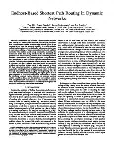
A. Simulation platform In order to implement and evaluate the proposed routing algorithm, a SystemC based communication framework has been developed. In this platform all the nodes in can send packets to any other nodes in the network. The purpose of this platform is to validate the working of the proposed routing algorithm and to analyze the average distance and frequency of hop counts in . In our simulations only one node at a time can send packet to any other node in the network because the scope of this work is not to find the performance of the network with all load conditions. Number of hops traversed by all packets along their paths, are stored in the communication history. This later is used for analysis. B. Simulation Results Verification of shortest path: For test and verification of GSR, (with 1024 nodes) is considered. The reason to choose large network size is to ensure that GSR is doing all the index conversions accurately with respect to the size of network. The simulation is done by grouping together 16 nodes into one block i.e. . There are a total of 63 blocks in . All the nodes inside one sender block are sending packets to all nodes inside the network. Sum of all the shortest paths are plotted in Fig. 18 as a result of block level communication. To verify all the shortest paths and hop counts in , the same simulations are done with Dijkstra‟s algorithm and a hop count of 1,048,576 possible shortest paths in are compared. It is observed that proposed algorithm produces exactly same hop counts for all possible shortest paths, as in case of the Dijkstra‟s algorithm. Fig. 18 shows the hop counts of all possible shortest paths in for GSR and Dijkstra‟s algorithm.
Figure 18. Total number of Hops counts generated by each block GSR in
Figure 17. Local block communcation method for local routing
Average distance & Frequency of hop counts: As discussed in section 4, the network properties of scales well with size of the network. In this section two other network properties of are presented i.e. average distance and frequency of hop counts. Small average distance improves average latency and throughput of overall system. Frequency of hop counts represents distribution of all possible shortest paths in overall network. Group based shortest path algorithm is used to http://journals.uob.edu.bh
Int. J. Com. Dig. Sys. 5, N. 2, 147-159 (March-2016) evaluate the average distance and frequency of hop counts in with different network size upto 1024 node. Average distance is plotted in comparison with 2-D Mesh, Spidergon, THIN networks. It is can be seen from Fig 19 that HCCR networks have small average distance in comparison to Spidergon and THIN for network size greater than 60 nodes, whereas there is only 7.7% increase in the average distance of HCCR ( ) in comparison to 2-D Mesh for a network size of 1024 nodes. Frequency hops counts in HCCR and 2-D Mesh are evaluated using shortest path routing algorithms. For 2-D Mesh XY algorithm is used. Results are plotted with different network size. It shows that HCCR has always fewer longer paths available and it get better as the network size scales. These results show that HCCR can be a good candidate for providing efficient and low cost communication with locality based traffic in many core systems.
157
algorithm under different network load conditions and comparing the performance with other interconnection networks.
Figure 20. Frequency hop counts in
9. CONCLUSION We have presented a new interconnection topology called the Hierarchical Cross Connected Recursive network (HCCR) and a shortest path routing algorithm for the HCCR. Network properties of HCCR networks are compared with Spidergon, THIN, 2-D Mesh and hypercube topologies. It is shown that the properties of HCCR make it suitable even for large network sizes due totter expansibility, small node degree and low diameter. We proposed a Group based Shortest Path Routing algorithm (GSR) to guarantee efficient communication in HCCR. The GSR for k-level HCCR ( ) with ( ) nodes, requires ( ) time in the worst case to determine the next node along the shortest path. Average distance for is measured by simulating GSR on with the help of SystemC based communication framework. All the shortest paths in network are verified by Dijkstra‟s algorithm. Our simulation results show that HCCR networks have a
Figure 21. Frequency hop counts in
Figure 22. Frequency hop counts in
REFERENCES [1]
Jeyapaul, Reiley, Fei Hong, Abhishek Rhisheekesan, Ashish Shrivastava, and Kyoungwoo Lee. "UnSync-CMP: Multicore CMP Architecture for Energy-Efficient SoftError Reliability." Parallel and Distributed Systems, IEEE Transactions on 25, no. 1 (2014): 254-263.
[2]
Farahabady, M. Hoseiny, Navid Imani, and Hamid Sarbazi-Azad. "Some topological and combinatorial properties of WK-recursive mesh and WK-pyramid interconnection networks." Journal of Systems Architecture 54, no. 10 (2008): 967-976.
[3]
Dijkstra, Edsger W. "A note on two problems in connexion with graphs."Numerische mathematik 1, no. 1 (1959): 269271.
Figure 19. Comparison of Average distance
have a small average distance in comparison to Spidergon and THIN, whereas there is only a 7.7% increase in the average distance of HCCR ( ) in comparison to 2-D Mesh for a network size of 1024 nodes. However HCCR have fewer longer paths as compared to a 2-D Mesh. Future research will focus on simulating HCCR networks with the shortest path routing
http://journals.uob.edu.bh
158 [4]
[5]
[6]
[7]
[8]
[9]
Omair Inam, et. al.: Group based Shortest Path Routing Algorithm …
Bononi, Luciano, and Nicola Concer. "Simulation and analysis of network on chip architectures: ring, spidergon and 2D mesh." In Proceedings of the conference on Design, automation and test in Europe: Designers' forum, pp. 154-159. European Design and Automation Association, 2006. Lee, Junghee, Chrysostomos Nicopoulos, Hyung Gyu Lee, and Jongman Kim. "TornadoNoC: A lightweight and scalable on-chip network architecture for the many-core era." ACM Transactions on Architecture and Code Optimization (TACO) 10, no. 4 (2013): 56. Siguenza-Tortosa, D., and Jari Nurmi. "Proteo: a new approach to network-on-chip." In IASTED International Conference on Communication Systems and Networks (CSN’02). 2002. Bourduas, S., B. Kuo, Z. Zilic, and N. Manjikian. "Modeling and evaluation of an energy-efficient hierarchical ring interconnect for System-on-Chip multiprocessors." In Circuits and Systems, 2006 IEEE North-East Workshop on, pp. 201-204. IEEE, 2006. Mirza-Aghatabar, Mohammad, Somayyeh Koohi, Shaahin Hessabi, and Massoud Pedram. "An empirical investigation of mesh and torus NoC topologies under different routing algorithms and traffic models." In Digital System Design Architectures, Methods and Tools, 2007. DSD 2007. 10th Euromicro Conference on, pp. 19-26. IEEE, 2007. Bourduas, Stephan, and Zeljko Zilic. "Modeling and evaluation of ring-based interconnects for Network-onChip." Journal of Systems Architecture 57, no. 1 (2011): 39-60.
[10] Loucif, Samia. "Performance evaluation of hierarchical-
torus NoC." InAdvanced Information Networking and Applications Workshops (WAINA), 2013 27th International Conference on, pp. 837-842. IEEE, 2013. [11] Balfour, James, and William J. Dally. "Design tradeoffs
for tiled CMP on-chip networks." In Proceedings of the 20th annual international conference on Supercomputing, pp. 187-198. ACM, 2006. [12] Karim, Faraydon, Anh Nguyen, Sujit Dey, and Ramesh
Rao. "On-chip communication architecture for OC-768 network processors." In Proceedings of the 38th annual Design Automation Conference, pp. 678-683. ACM, 2001. [13] Bononi, Luciano, and Nicola Concer. "Simulation and
analysis of network on chip architectures: ring, spidergon and 2D mesh." In Proceedings of the conference on Design, automation and test in Europe: Designers' forum, pp. 154-159. European Design and Automation Association, 2006.
[14] Xue,
Licheng, Feng Shi, and Weixing Ji. "3D floorplanning of low-power and area-efficient Networkon-Chip architecture." Microprocessors and Microsystems 35, no. 5 (2011): 484-495.
[15] Yu, Xin, and Tao-shen Li. "On shortest path routing
algorithm in crossed cube-connected ring networks." In Cyber-Enabled Distributed Computing and Knowledge Discovery, 2009. CyberC'09. International Conference on, pp. 348-354. IEEE, 2009. [16] Dobravec, Tomaž, Janez Žerovnik, and Borut Robič. "An
optimal message routing algorithm for circulant networks." Journal of Systems Architecture 52, no. 5 (2006): 298-306. [17] Su, Ming-Yang, Gen-Huey Chen, and Dyi-Rong Duh. "A
shortest path routing algorithm for incomplete WKrecursive networks." Parallel and Distributed Systems, IEEE Transactions on 8, no. 4 (1997): 367-379. [18] Nguyen, Ngoc Chi, Thanh Vu Dinh, and Tuan Dang Anh.
"Improving shortest path routing in hyper-de Bruijn networks." In Strategic Technology, 2007. IFOST 2007. International Forum on, pp. 288-292. IEEE, 2007. [19] Yang, Xiaofan, Graham M. Megson, and David J. Evans.
"An oblivious shortest-path routing algorithm for fully connected cubic networks." Journal of Parallel and Distributed Computing 66, no. 10 (2006): 1294-1303. [20] Sau, Ignasi, and Janez Zerovnik. "An optimal permutation
routing algorithm for full-duplex hexagonal mesh networks." Preprint series, University of Ljubljana, Institute of Mathematics, Physics and Mechanics 44 (2006): 1017. [21] Jha, Sudhanshu Kumar, and Prasanta K. Jana. "Shortest
Path Routing on Multi-Mesh of Trees." In Proceedings of the World Congress on Engineering, vol. 2. 2011. [22] Qiao, Baojun, Feng Shi, and Weixing Ji. "A New
Hierarchical Interconnection network for multi-core processor." In Industrial Electronics and Applications, 2007. ICIEA 2007. 2nd IEEE Conference on, pp. 246-250. IEEE, 2007. [23] Zuo, W. A. N. G., and S. H. I. Feng. "A Shortest Path
Routing Algorithm Network." Transactions of Technology 5 (2009): 011.
in Beijing
Triplet-Based Institute of
[24] Zhang, Yang, and Feng Shi. "Design and Evaluation of
Low-Latency and Shortest-Path Routing Algorithm for Triplet-Based Hierarchical Interconnection Network." JOURNAL OF TESTING AND EVALUATION 41, no. 4 (2013): 541-550.
http://journals.uob.edu.bh
Int. J. Com. Dig. Sys. 5, N. 2, 147-159 (March-2016) Omair Inam is a PhD student in Computer Engineering, at COMSATS Institute of Information Technology. He obtained Master Degree in Electronic Engineering in 2008 from University of Sheffield, UK. He completed Bachelor Degree in Computer Engineering from Islamic International Engineering College Pakistan in 2002. His research area include Network-onChip, Computer Architecture and System Level Modeling
Sharifa Al Khanjari is a PhD student in Embedded, Networked and Distributed Systems (ENDS) at the School of Computing Science of the University of Glasgow. She received a Master and Bachelor Degree in Computer Science from Sultan Qaboos University, Oman in 2007 and 2010, respectively. Her research focus on the architecture of many
159
Dr Wim Vanderbauwhede is Lecturer in Embedded, Networked and Distributed Systems at the School of Computing Science of the University of Glasgow. His research focuses on high-level programming, compilation and architectures for heterogeneous manycore systems and FPGAs, with a special interest in powerefficient computing. He is author of the book "HighPerformance Computing Using FPGAs". He received a PhD in Electrotechnical Engineering with Specialisation in Physics from the University of Gent, Belgium in 1996.
http://journals.uob.edu.bh