Vehicle System Dynamics Vol. 45, No. 3, March 2007, 233–247
H2 optimal control of disturbance-delayed systems with application to vehicle suspensions LEI ZUO*† and SAMIR A. NAYFEH‡ †GPRD – Automation Engineering, Abbott Laboratories, R46S AP52S, 200 Abbott Park Road, Abbott Park, IL 60064, USA ‡Department of Mechanical Engineering, Massachusetts Institute of Technology, Cambridge, MA 02139, USA Optimal control of systems with time delays among disturbances, such as vehicle suspensions, is a relatively simple but long-standing problem in time-delayed control. We consider the exact H2 optimal control of systems with time-delayed disturbances and develop a computationally efficient approach for controller synthesis. We extend the Lyapunov-based H2 norm computation to systems with timedelayed disturbances and then derive a concise formula to explicitly evaluate the sensitivity of the system H2 norm with respect to controller gains. Thence, a set of necessary conditions for H2 optimal control of such systems using static output feedback are obtained in the form of algebraic equations. Gradient-based methods are adapted to optimize the controller gains. The method is also extended to reduced-order and decentralized control. As an application, a passive suspension system for an eightDOF four-wheel vehicle is designed via structured H2 optimization. The results are compared with those of a design based on a Pade expansion for the time delays and a design obtained by neglecting the disturbance delays.
1. Introduction H2 or LQG optimal control is one of the most widely used techniques for design of vehicle suspensions for the conflicting objectives of ride comfort, road handling, vehicle chassis motion, and suspension working space [1]. Comprehensive surveys of optimal control techniques applied to vehicle suspensions can be found in the papers by Wilson et al. [2] and Hrovat [3]. One special consideration in the dynamics of vehicle suspensions is the time delay among the disturbances. The excitation of vehicle vibration is primarily due to road irregularities, which act on the front wheels before acting on the rear wheels. Time delays arise in many physical systems from the transport of materials and information or delays in measurement and computation. Time-delayed systems are actually a class of infinite-order systems, and their control is generally far more complicated than that of delayfree systems [4–6]. Though for stability concern disturbance-delayed systems are generally of finite order, its optimal control still becomes infinite order. The optimal control of systems in which the delays are confined to the disturbance inputs is a comparatively simple but important and long-standing problem. *Corresponding author. Email:
[email protected]
Vehicle System Dynamics ISSN 0042-3114 print/ISSN 1744-5159 online © 2007 Taylor & Francis http://www.tandf.co.uk/journals DOI: 10.1080/00423110600884288
234
Lei Zuo and S. A. Nayfeh
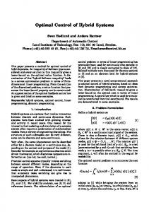
Figure 1.
Control of systems with disturbance delay.
As shown by Rill [7], Sharp and Wilson [8], and Crolla and Abdel-Hady [9], the performance of a vehicle suspension can be significantly decreased if the delay in disturbances is ignored. Several methods have been proposed to account for delays among disturbances in optimal control. Louam et al. [10] took the delay time as an integer multiple of the sampling interval and developed an approach based on discrete-time optimal control. However, several important issues of implementation remained outside the scope of the study. Another commonly used approach is imperfect approximation of the time delay using Pade expansions [9, 11– 14]. However, the order of the system is increased substantially, which is a disadvantage in controller design and implementation. Hac [15], Hac and Youn [16], and Marzbanrad et al. [17] developed a continuous-time optimal control method including preview and delay, but the method developed is limited to full-state feedback and a road surface measurement is needed. Hedrick and Firouztash [18] derived a covariance differential equation for the case where two of the inputs are related by a time delay. Sharp and Wilson [8] obtained an equation for evaluation of the LQ cost with time delay and used the Simplex method to search for the full-state feedback control of a half-car suspension. Harrison [13] examined the theoretical solution of the full-state-feedback LQG problem with disturbance delays and obtained a set of partial differential equations of the Riccatti type, but computation of solutions remained outside the scope of the study. The purpose of this article is to provide an efficient approach for exact H2 optimization of output-feedback controllers for systems with delays in their disturbances and to apply it to the design of vehicle suspensions. Building on the work of Hedrick and Firouztash [18] and Sharp and Wilson [8], we extend the Lyapunov-based computation of the H2 norm to systems with input time delays. Then, we derive an explicit formula to evaluate the sensitivity of the H2 norm of such systems to static-output feedback gains and thence derive a set of necessary conditions for H2 optimal control of disturbance-delayed systems in the form of algebraic equations. Gradient-based methods are adapted for the computation. The approach is also extended to lower order and decentralized H2 optimal control. As an example, a passive suspension for a full-car model is designed using decentralized H2 optimization, accounting for the delays among the disturbances and then compared to a suspension designed by ignoring the delays.
2.
H2 norm of systems with time-delayed disturbances
2.1 Problem statement For the minimally realized LTI system with time-delayed disturbances given by x(t) ˙ = Ax(t) + B11 w(t) + B12 w(t − τ ) + B2 u(t)
H2 optimal control of disturbance-delayed systems
235
z(t) = C1 x(t) + D111 w(t) + D112 w(t − τ ) + D12 u(t)
(1)
y(t) = C2 x(t) where τ is the magnitude of the time delay, design a static output-feedback law u = F y(t)
(2)
such that the H2 norm of the closed-loop system w → z is minimized. For a causal LTI system, the H2 norm is defined as the signal 2-norm of the system’s impulse response matrix hzw (t) or, equivalently, the asymptotic value of system’s output variance (i.e. the RMS value) with unit white-noise input. That is, kH k22
=
Z
∞
trace[h′zw (t)hzw (t)] dt
(3)
0
For the time-delayed system given by equation (1), with the feedback given by equation (2), the impulse response is h(t) =
(
Cc eAc t B11 + D111
if 0 ≤ t < τ
Cc eAc t (B11 + e−Ac τ B12 ) + D111 + D112
if t ≥ τ
(4)
where Ac = A + B2 F C2 and Cc = C1 + D12 F C2 . Substituting the expression for the impulse response given by equation (4) into the definition of the H2 norm, equation (3), we see that the H2 norm is infinite if Ac = A + B2 F C2 has any negative eigenvalues or D111 + D112 is not zero. We consider the case where D111 = 0 and D112 = 0. Then, Z τ 2 ′ A′c t ′ kH k2 = trace B11 e Cc Cc eAc t B11 dt 0
+ trace
Z
∞
τ
′
′
′ ′ −Ac τ Ac t ′ (B11 + B12 e )e Cc Cc eAc t (B11 + e−Ac τ B12 ) dt
By changing the limits of the integrals, we obtain kH k22
= trace
Z
∞
0
+ trace
Z
0
′ A′c t ′ B11 e Cc Cc eAc t B11 ∞
′ (B11 e
A′c τ
′ + B12 )e
dt − trace
A′c t
Z
∞
0
′
′
′ Ac τ Ac t ′ B11 e e Cc Cc eAc t eAc τ B11 dt
Cc′ Cc eAc t (eAc τ B11 + B12 ) dt
(5)
If Ac is stable, we can write the equivalence [19] K=
Z
0
∞
′
eAc t Cc′ Cc eAc t dt ⇐⇒ KAc + A′c K + Cc′ Cc = 0
(6)
which can be used to replace the integrals in equation (5) to obtain ′
′ ′ ′ Ac τ ′ kH k22 = trace(B11 KB11 + B12 KB12 + B11 e KB12 + B12 KeAc τ B11 ).
If τ = 0, we recover the fundamental result [19] of H2 optimal control of systems without delay. This analysis is restated as Theorem 1.
236
Lei Zuo and S. A. Nayfeh
THEOREM 1 For the minimally realized LTI system, x(t) ˙ = Ac x(t) + B11 w(t) + B12 w(t − τ ) z(t) = Cc x(t) + D111 w(t) + D112 w(t − τ )
(7)
with disturbance delay τ . The system H2 norm from w to z is infinite if Ac is unstable or D111 + D112 6= 0. If Ac is stable, D111 = 0 and D112 = 0. Then, ¡ ′ ¢ ′ ′ A′c τ ′ kH k22 = trace B11 KB11 + B12 KB12 + B11 e KB12 + B12 KeAc τ B11
(8)
KAc + A′c K + Cc′ Cc = 0
(9)
where K is a symmetric matrix (the observability Gramian) which solves the Lyapunov equation
3. Necessary conditions of H2 optimization Theorem 1 provides a direct method for computation of the H2 norm of systems with timedelayed disturbances. From Theorem 1, the problem of H2 optimal control for the system given by equation (1) using static output feedback becomes ′
′ ′ ′ Ac τ ′ KB11 + B12 KB12 + B11 e KB12 + B12 KeAc τ B11 ) min J (F ) = kH k22 = trace(B11
s.t. KAc +
A′c K
+
Cc′ Cc
(10)
=0
where Ac = A + B2 F C2 is stable and Cc = C1 + D12 F C2 . A challenge in solving this problem arises from the presence of the matrix exponential in the argument of the trace function. Brewer [20] used Kronecker products to derive an expression for the derivative of the exponential matrix with respect to a matrix. It is feasible to use his result and the gradient chain rule to evaluate the derivative of our objective function with respect to a matrix, but the computation is not efficient. We use simple mathematics to derive a concise expression for the gradient of the trace function of general exponential matrices with respect to a matrix, as stated in the following lemma. LEMMA 1 S, M, N, and X are real matrices of dimension n × n, n × m, m × r, and r × n, respectively, and τ is a scalar. Suppose MXN is diagonalizable, then ∂ trace(Se ∂X
MXNτ
)
= M′
n X n X j =1 l=1
wj′ S ′ vl fj l (τ )vj wl′ N ′
(11)
where vi and wi are the ith normalized right and left eigenvectors of (MXN)′ , λi is the corresponding eigenvalue, and λj τ τ e fj l (τ ) = eλj τ − eλl τ λj − λl
if λj = λl if λj 6= λl
(12)
237
H2 optimal control of disturbance-delayed systems
Proof Making use of the definition of the matrix exponential, we write "∞ # X τk S(MXN)k trace(SeMXNτ ) = trace k! k=0 Using the following formulas of matrix calculus [21] ∂ trace(Y X′ Z) = ZY ∂X
∂ trace(Y XZ) = Y ′Z′, ∂X we obtain ∞
∂ trace(SeMXNτ ) X τ k ∂ trace[S(MXN)k ] = ∂X k! ∂X k=0 ∞ k X τk X
M ′ (N ′ X′ M ′ )i−1 S ′ (N ′ X ′ M ′ )k−i N ′ k! k=0 i=1 "∞ k # X X τk ′ ′ ′ ′ i−1 ′ ′ ′ ′ k−i (N X M ) S (N X M ) =M N′ k! k=0 i=1
=
Because MXN is diagonalizable, we can write the matrix MXN in its spectral representation as (MXN)′ =
n X
vj wj′ λj
j =1
where vj′ wl = 1 if j = l, vj′ wl = 0 if j 6= l. Then, ∂ trace(Se ∂X
MXNτ
)
= M′
k ∞ X n X τk X k=0 i=1
k!
′ vj wj′ λi−1 j S
j =1
n X l=1
Noting that wj′ S ′ vl is a scalar, we write ∂ trace(Se ∂X
MXNτ
)
= M′
n n X X j =1 l=1
wj′ S ′ vl vj wl′
vl wl′ λlk−i N ′
k ∞ X X τk k=0 i=1
k−i ′ N λi−1 j λl
k!
P Pk i−1 k−i k We simplify ∞ as fj l (τ ), as shown in equation (12). Therefore, k=0 i=1 (τ /k!)λj λl Lemma 1 is proved. ¥ A set of necessary conditions for H2 optimization of systems with input time delay can be obtained from Lemma 1. On the basis of the problem specified by equation (10), we define a Lagrangian function of the form ′
′ ′ ′ Ac τ L(F, K, L) = trace[B11 KB11 + B12 KB12 + B11 e KB12
′ + B12 KeAc τ B11 + (KAc + A′c K + Cc′ Cc )L]
(13)
where L is a (symmetric) Lagrange multiplier matrix, Ac = A + B2 FC2 , and Cc = C1 + D12 FC2 . Using matrix calculus [21] and Lemma 1, we evaluate the first derivatives of L(F, K, L) with respect to the matrices F , K, and L and obtain Theorem 2.
238
Lei Zuo and S. A. Nayfeh
THEOREM 2 Suppose D111 = D112 = 0 in the time-delayed system of equation (1). A set of necessary conditions for optimal H2 control with the static output feedback u = F y are ∂L = K(A + B2 FC2 ) + (A + B2 FC2 )′ K + (C1 + D12 FC2 )′ (C1 + D12 FC2 ) = 0 (14) ∂L ∂L ′ ′ ′ = L(A + B2 FC2 )′ + (A + B2 FC2 )L + B11 B11 + B12 B12 + e(A+B2 FC2 )τ B11 B12 ∂K ′
′ (A+B2 FC2 ) τ + B12 B11 e =0
∂L ′ ′ D12 FC2 + D12 C1 + B2′ K)LC′2 = 2(D12 ∂F n n X X ′ + 2B2′ wj′ KB12 B11 vl fj l (τ )vj wl′ C2′ = 0
(15)
(16)
j =1 l=1
where the vi and wi are the ith normalized right and left eigenvectors of (A + B2 F C2 )′ , λi is the corresponding eigenvalue, and λ τ if λj = λl τ e j fjl (τ ) = eλj τ − eλl τ if λj 6= λl λ j − λl
Note that the necessary conditions for an optimal solution are expressed in the form of algebraic equations rather than partial differential equations.
4. Algorithm and extensions 4.1 Algorithm Theorem 2 provides a set of necessary conditions for H2 optimal control of systems with delayed disturbances under static output feedback. It is not easy to directly solve this set of nonlinear matrix equations involving the matrix exponentials associated with the time delay for the matrix variables K, L, and F , but a gradient-based method can be adapted to efficiently compute the optimal controller gains. As in delay-free H2 optimal control, we find that the gradient of the cost kH k22 with respect to the feedback gain matrix F is equal to the gradient of the Lagrangian L with respect to F under the condition that both ∂L/∂L = 0 and ∂L/∂K = 0. Note that, for a given F , ∂L/∂L = 0 and ∂L/∂K = 0 are two decoupled matrix Lyapunov equations which can be solved easily. These observations form the basis for a gradient-based method summarized in the following: Step 1. Find a feedback gain F stabilizing A + B2 FC2 . Many approaches for static-out stabilization can be used for this initialization [22]. Step 2. Solve the decoupled Lyapunov equations given by equations (14) and (15) for L and K. Then evaluate the gradient dkH k22 /dF = ∂L/∂F according to equation (14). If the norm of dkH k22 /dF is small enough, stop; otherwise go to step 3. Step 3. On the basis of the gradient dkH k22 /dF , calculate a search direction DF using the steepest descent, conjugate gradient, or FBGS quasi-Newton method (for details, see ref. [23]). Choose a proper step size α (using the minimization rule, Armijo rule, or other method), with the additional requirement that A + B2 (F + αDF )C2 be stable. Update F with F + αDF . Go to step 2.
H2 optimal control of disturbance-delayed systems
4.2
239
Extentions
We have discussed the H2 optimal control of systems with time-delayed disturbances using static output feedback. For full-state feedback, we can simply assume that C2 = I in the earlier mentioned procedure. Note that because of the exponential items, we cannot obtain an algebraic Riccati equation for the optimal solution as can be found in the case of full-state feedback without delay. We can also cast the problem of reduced-order optimal control with time-delayed disturbances as static output-feedback optimal control of an augmented plant. Details are given in the Appendix. Zuo and Nayfeh [14] have cast the optimal design of passive vehicle suspensions as a decentralized feedback optimization problem by taking the suspension springs and shock absorbers as local feedback elements of relative displacements and velocities. For static decentralized control, the feedback gains have a block diagonal structure: F1 F2 (17) F = .. . Fk
Because of the structure of F , Theorem 2 does not hold for the decentralized case. Recall the meaning of the derivative with respect to a matrix: ∂L/∂F is a collection of (∂L/∂Fij ). For decentralized feedback, the design variables are the entries of the diagonal blocks inside F . Therefore, equation (16) must be revised by picking out the entries corresponding to the free variables. That is, ∂L ′ ′ D12 FC2 + D12 C1 + B2′ K)LC′2 = 2(D12 ∂F n n X X ′ ′ ′ ′ ′ + 2B2 wj KB12 B11 vl fj l (τ )vj wl C2 ⊙ Fp (18) j =1 l=1
where Fp is a matrix of the same dimension as F , with entry 1 in the positions corresponding to the free design variables in F and zero elsewhere, and X ⊙ Fp denotes multiplication of X and Fp entry by entry. Using the revised formula given by equation (18) and the two decoupled Lyapunov equations given by equations (14) and (15), we can apply the gradient-based method of this article to H2 optimization of decentralized controllers for systems with time-delayed disturbances.
5. Application: decentralized H2 optimization of a passive vehicle suspension A vehicle suspension is a typical example of a system in which there are time delays among the disturbances. In this section, we apply the proposed method to optimization of a passive vehicle suspension and compare the results with those of a design based on Pade expansions and a design in which the time delays are ignored. 5.1
Formulation and problem specification
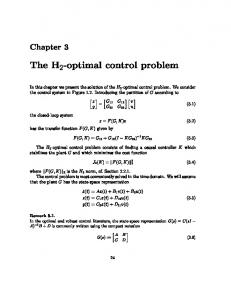
Figure 2 shows a four-wheel vehicle model. The vehicle chassis is modeled as a rigid body with three DOF (heave, roll, and pitch), and the wheels and driver’s seat are each considered to be
240
Lei Zuo and S. A. Nayfeh
Figure 2. An eight-DOF full-car model.
one-DOF masses. The ground roughness at the left and right tracks are taken as uncorrelated disturbance excitations. The excitations at the rear axle is a pure delay of those at the front axle. The delay time τ = l/V , where l is the distance between axles and V is the vehicle speed. Because the road roughness is typically represented as a stationary Gaussian stochastic process of a given displacement power spectral density, the displacement disturbance to the vehicle tire can be generated by white noise w(t) passed through a first-order filter [14] √ 2π Gr V G(s) = s + 2π V υ0
(19)
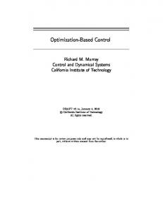
where Gr is the road roughness coefficient in m2 × cycle/m and υ0 is the spatial cut-off frequency (usually around 0.001–0.02 cycle/m). The goal of passive suspension design is to choose the suspension stiffness and damping parameters to meet comprehensive performance requirements on ride comfort, road handling, and chassis motion in a limited suspension working space. Ride comfort is measured by the RMS acceleration at the passenger seat weighted by the human-vibration sensitivity curves specified by the ISO 2631 standard [24]. In order to use the frequency weighting curves in design, we design low-order quasi-least-square filters that approximate the ISO 2631 weighting curves using bilinear transforms [25]. We obtain a fourth-order shape filter for vertical acceleration given by W (s) =
81.89s 3 + 796.6s 2 + 1937s + 0.1446 s 4 + 80.00s 3 + 2264s 2 + 7172s + 21196
(20)
and plotted in figure 3. The road handing is measured by the dynamic contact force on the tires, which is proportional to the tire deformations. The cost outputs include the performance indices of ride comfort, road handing, chassis motion, and suspension deformations, which are weighted by the factors ei to make tradeoffs among the various indices. Thus, the cost output vector z(t) is written as z(t) = [e1 z¨˜ p , e2 z˙ b , e3 θ˙x , e4 θ˙y , e5 dfl , e6 dfr , e7 drl , e8 drr , e9 ffl , e10 ffr , e11 frl , e12 frr ]′
(21)
241
H2 optimal control of disturbance-delayed systems
Figure 3. ISO 2631 frequency weighting curve (circles) and the fourth-order filter approximation (solid line).
where z¨˜ p represents the acceleration z¨ p at driver’s seat passed through the ISO 2631 filter; z˙ b , θ˙x , and θ˙y are the vehicle chassis motions of heave, roll, and pitch; dfl , dfr , drl , and drr are suspension deformations; ffl , ffr , frl , frr are the dynamic tire–ground contact forces. We replace the role of the springs and dampers of the passive suspension by a ‘control force’ vector u, which is generated by a block-diagonal gain F multiplied by the vector y comprising the suspension deformations and deformation rates: kfl u = Fy =
cfl kfr
cfr krl
crl krr
crr
y
(22)
We see that the block-diagonal controller gain is composed of the suspension stiffness and damping parameters, and the optimization of the passive vehicle suspension becomes a decentralized control problem with time-delayed disturbances. This formulation is shown in figure 4 and can be written in the standard form given in figure 1. Because the disturbance is random, H2 optimization yields a meaningful design which minimizes the RMS value of z(t). A procedure for the suspension system design based on H2 optimization in which a fourthorder Pade expansion is used to approximate the delay has been developed by the authors [14]. The suspension parameters can be guaranteed to be nonnegative by replacing Fij by Fij2 , and the suspension-symmetry requirement that the left and right parameters be equal can be incorporated with minor modification [14]. Details of the vehicle parameters, obtained from Kim and Yoon [26], are listed in table 1.
242
Lei Zuo and S. A. Nayfeh
Figure 4.
Decentralized control formulation of passive suspension system.
Table 1.
Parameters and nomenclature of an eight-DOF full-car model.
Description Sprung mass Sprung moment of inertia about x-/y-axis Unsprung mass (front/rear) Mass of driver’s seat Vertical stiffness of one tire (front/rear) Suspension stiffness per wheel (front/rear) Suspension damping per wheel (front/rear) Vertical stiffness of driver’s seat Damping coefficient of driver’s seat Distance between x-axis and front/rear tires Distance between y-axis and front/rear tires Distance between x-axis and driver’s seat Distance between y-axis and driver’s seat Vertical displacement of driver’s seat Attitude of vehicle chassis: heave, roll, pitch Suspension deformation Dynamic contact force of tires
Symbol
Value
mb Ix , Iy m t , mr mp ktf , ktr kfl , kfr , krl , krr cfl , cfr , crl , crr kp cp ll , lt l f , lr lp1 lp2 zp z b , θ x , θy dfl , dfr , drl , drr ffl , ffr , frl , frr
1375.9 kg 484.4/2344.4 kg m2 40/40 kg 60 kg 182087/182087 N/m
10507.1 N/m 875.6 Ns/m 0.72/0.72 m 1.125/1.511 m 0.24 m 0.34 m
In this example, we take the spatial cut-off frequency υ0 = 0.005 cycle/m and the weighting factors as
5.2
Weighting factor
e1
Value
1
e2 8.3
e3 8.3
e4
e5 –e8
e9 –e12
120
120
8.3e-3
Results and discussion
The generalized plant model is 22nd-order plus two disturbance delays. Using the proposed method, we optimize the passive suspension parameters for a vehicle speed of 30 m/s; the resulting parameters are given in the first row of table 2. For comparison, we obtain a 30thorder rational plant using two fourth-order Pade approximations for the delays. The parameters optimized based on this plant are given in the second row of table 2, from which we see that
243
H2 optimal control of disturbance-delayed systems Table 2. Suspension parameters designed using the proposed direct H2 optimization with disturbance delays, Pade delay approximation, and by ignoring the disturbance delays. Front suspension
Direct optimization Pade approximation Delay ignored
Rear suspension
kfl = kfr
cfl = cfr
krl = krr
crl = crr
17,400 17,406 19,428
2383 2381 2399
19,200 19,214 17,008
2435 2429 2179
the Pade expansion yields a controller very close to the true optimum. The design given in the third row of table 2 is obtained by ignoring the time delay. It is far from the true optimum. The corresponding performances achieved on a class B road (Gr = 1.6 × 10⁻⁶ m2 ·cycle/m) at a vehicle speed of 30 m/s are shown in table 3. Note that the performance indices given in the table for each method are the ‘calculated performances’ obtained using the respective method. The true performances are computed using Theorem 1. From this table, we see that all of the indices obtained using the Pade expansion are very close to the true optima. However, direct H2 optimization of the system with time-delayed disturbances as proposed in this article is computationally more efficient because it does not increase the order of the generalized plant, as do the additional states used in the Pade expansion. In contrast, if the time delay is ignored, the comfort index is overestimated by 37% and the pitch motion of the vehicle chassis is underestimated by 70%. To aid in understanding the effects of the delay, we compute the frequency responses from the excitations at the left and right tracks using each of the three methods. Figure 5 shows the responses of the weighted acceleration at driver’s seat, the deformation of the front-right suspension, and the dynamic contact force on the front-right tire. Figure 6 shows the responses of the chassis motions. Note that these response curves include the road spectral filter G(s) given by equation (19) and the human-vibration sensitivity weighting W (s) given by equation (20). In each plot, we compare the responses of the system exactly optimized, the system obtained using Pade expansions, and the system obtained by ignoring the time delays. The time delay leads to phase differences between the excitations acting at the respective wheels. At certain frequencies, these phase differences cause some components of the response
Table 3.
Comparison of the performance indices for the systems obtained by each method.
Performances Total H2 norm RMS acceleration z¨˜ p , m/s2
RMS suspension travel, mm Front average Rear average RMS normalized dynamic contact force, % Front average Rear average
RMS vehicle chassis motion Heave, cm/s Roll, ×10−2 rad/s Pitch, ×10−2 rad/s
A
B
C
6.6530 0.2141
6.6519 0.2141
6.7478 0.2935
5.0800 3.8331
5.0820 3.8374
4.7586 4.5470
8.8261 11.347
8.8274 11.342
8.9344 11.8639
3.0787 4.4687 1.0043
3.0802 4.4709 1.0027
3.3196 5.2896 0.3060
Note: (A) Direct optimization, (B) Pade expansion, and (C) delay neglected. The true total H2 norm computed using equation (8) for case (B) is 6.6531 and for case (C) is 6.6692.
244
Lei Zuo and S. A. Nayfeh
Figure 5. Frequency responses of weighted acceleration at driver’s seat, deformation of front-right suspension, and dynamic force of front-right tire: exact (solid), Pade expansion (dot), and delay neglected (dash).
to be sharply reduced relative to those predicted without the delays, leading to the valleys in the frequency responses of many of the indices. As shown in figure 5, neglect of the time delay in disturbances causes the low-frequency responses of the suspension deformations and dynamic tire–ground forces to be underestimated. It is relatively difficult to excite the pitch motion by disturbances simultaneously acting on the front and rear wheels; therefore, pitch motion is underestimated at almost all frequencies if the time delay in the disturbances on the front and rear wheels is neglected, as shown in figure 6. Figures 5 and 6 show that the Pade expansion is a good approximation only at low frequencies (below 11 Hz in this example). The errors in the high-frequency responses are significant.
H2 optimal control of disturbance-delayed systems
245
Figure 6. Frequency responses of chassis motions: exact (solid), Pade expansion (dot), and delay neglected (dash).
6. Conclusions Optimal control of systems with time-delayed disturbances is a long-standing problem. In this article, we examine the exact solution for H2 optimal control of systems with disturbance time delays. We develop an efficient computational approach and demonstrate its application to a vehicle suspension. First, the Lyapunov-based computation of the H2 norm is extended to systems with disturbance time delays. Then, we derive a concise formula to explicitly evaluate the sensitivity of the H2 norm of such a system with respect to the controller gains. A set of necessary conditions for H2 optimal control of disturbance-delayed systems with static output feedback
246
Lei Zuo and S. A. Nayfeh
are obtained in the form of algebraic equations, and gradient-based methods are adapted to directly optimize the controller gains. As an application, a passive vehicle suspension for an eight-DOF full-car model is optimized within the framework of structured H2 optimal control with disturbance delays. It is found that significant performance losses occur if the time delays are ignored. A Pade expansion of sufficient order can be used as a good approximation to the time delays, but the responses at high (and medium) frequencies are inaccurate. Moreover, the proposed H2 optimization for disturbance-delayed systems is computationally more efficient than that based on Pade expansions because it does not increase the order of the generalized plant.
References [1] Ulsoy, A.G., Hrovat, D. and Tseng, T., 1994, Stability robustness of LQ and LQG active suspensions. ASME Journal of Dynamic Systems, Measurement, and Control, 116, 123–131. [2] Wilson, D.A., Sharp, R.S. and Hassan, S.A., 1986, The application of linear optimal control theory to the design of active automobile suspensions. Vehicle System Dynamics, 15, 105–118. [3] Hrovat, D., 1997, Survey of advanced suspension developments and related optimal control applications. Automatica, 33, 1781–1817. [4] Watanabe, K., Nobuyama, E. and Kojima, A., 1996, Recent advances in control of time delay systems – a tutorial review. Proceedings of the 35th IEEE Conference on Decision and Control, pp. 2083–2089. [5] Mirkin, L. and Tadmor, G., 2002, H∞ control of systems with I/O delay: a review of some problem-oriented methods. IMA Journal of Mathematical Control and Information, 19, 185–199. [6] Gu, K. and Niculescu, S., 2003, Survey on recent results in the stability and control of time delay systems. Journal of Dynamic Systems Measurement, and Control, 125, 158–165. [7] Rill, G., 1983, The influence of correlated random road excitation processes on vehicle vibration. Proceedings of 8th IAVSD Symposium on Dynamics of Vehicles on Roads and Tracks. [8] Sharp, R.S. and Wilson, D., 1990, On control laws for vehicle suspensions accounting for input correlations. Vehicle System Dynamics, 19, 353–363. [9] Crolla, D.A. and Abdel-Hady, M.B.A., 1991, Active suspension control: Performance comparisons using control laws applied to a full vehicle model. Vehicle System Dynamics, 20, 107–120. [10] Louam, N., Wilson, D.A. and Sharp, R.S., 1988, Optimal control of a vehicle suspension incorporating the time delay between front and rear wheel inputs. Vehicle System Dynamics, 17, 317–336. [11] Fruhauf, F., Kasper, R. and Luckel, J., 1986, Design of an active suspension for a passenger vehicle model using input processes with time delay. Proceedings of 9th IAVSD Symposium on Dynamics of Vehicles on Roads and Tracks. [12] Abdel-Hady, M.B.A. and Crolla, D.A., 1992, Active suspension control algorithms for a four wheel vehicle model. International Journal of Vehicle Design, 13(2), 144–158. [13] Harrison, R.F., 1993, Optimal control of vehicle suspension dynamics incorporating front-rear excitation delay: An approximate solution. Journal of Sound and Vibration, 168(2), 339–354. [14] Zuo, L. and Nayfeh, S., 2003, Structured H2 optimization of vehicle suspensions based on multi-wheel models. Vehicle System Dynamics, 40(5), 351–371. [15] Hac, A., 1992, Optimal linear preview control of active suspension. Vehicle System Dynamics, 21, 167–195. [16] Hac, A. and Youn, I., 1993, Optimal design of active and semi-active suspensions including time delay and preview. ASME Journal of Vibration and Acoustics, 115, 498–508. [17] Marzbanrad, J., Ahmadi, G., Hojjat, Y. and Zohoor, H., 2002, Optimal active control of vehicle suspension system including time delay and preview for rough roads. Journal of Vibration and Control, 8, 967–991. [18] Hedrick, J.K. and Firouztash, H., 1974, The covariance propagation equation including time-delayed inputs. IEEE Transactions on Automatic Control, 19, 587–589. [19] Zhou, K., Doyle, J. and Glover, K., 1995, Robust and Optimal Control (Prentice Hall). [20] Brewer, J., 1977, The derivative of the exponential matrix with respect to a matrix. IEEE Transactions on Automatic Control, ACS-22, 656–657. [21] Graham, A., 1981, Kronecker Products and Matrix Calculus: with Applications (John Wiley & Sons). [22] El Ghaoui, L., Oustry, F. and AitRami, M., 1997, A cone complementarity linearization algorithm for static output-feedback and related problems. IEEE Transactions on Automatic Control, 42, 1171–1176. [23] Bertsekas, D.P., 1995, Nonlinear Programming (Athena Scientific). [24] International Organization for Standardization, 1997, ISO 2631-1:1997, Mechanical vibration and shock – evaluation of human exposure to whole body vibration – part 1: General requirements. [25] Zuo, L. and Nayfeh, S., 2003, Low-order continuous-time filters for approximation of ISO 2631-1 humanvibration sensitivity weightings. Journal of Sound and Vibration, 265(2), 459–465. [26] Kim, H. and Yoon, Y., 1995, Semi-active suspension with preview using a frequency-shape performance index. Vehicle System Dynamics, 24, 759–780.
H2 optimal control of disturbance-delayed systems
247
Appendix: Reduced-order control of disturbance-delayed systems It is well known that reduced-order optimal control of systems can be handled within the framework of static output feedback. Systems with time-delayed disturbances also maintain this property. Suppose that xk is the state vector of a kth order controller for the nth order disturbancedelayed plant given by equation (1): x˙k = Ak xk + Bk y u = Ck xk + Dk y
(A1)
Defining the augmented states x, ˜ control u, ˜ and measurement y˜ as · ¸ · ¸ · ¸ x x˙k x x˜ = , and y˜ = k , u˜ = xk u y and reorganizing equations (1) and (A1), we find that the controller matrices of the kth order controller can be taken as the ‘static output-feedback gain’ · ¸ Ak Bk ˜ F := (A2) Ck Dk of an augmented plant of order k + n of the form · ¸ · ¸ · ¸ · ¸ | B A 0 B 0 B 11 11 2 | 0 0 0 0 Ik×k 0 | k×k | ˜ ˜ ˜ ˜ B12 B2 | A | B11 | £ ¤ ¤ := £ || C˜1 | D˜111 D˜112 D˜12 0 D12 D112 · C1 0 ¸ | D111 | | ˜ C2 | | 0 Ik×k | C2 0 | (A3)