using only a monoscopic video as input.2,3 Figure 2 .... Delete names that don't correspond to streets (see. Figure ... If F(x,y,z) 1, then point (x,y,z) lies outside the.
Feature Article
Haptic Rendering of Visual Data for the Visually Impaired Konstantinos Moustakas, Georgios Nikolakis, Konstantinos Kostopoulos, Dimitrios Tzovaras, and Michael G. Strintzis Aristotle University of Thessaloniki Informatics and Telematics Institute, Thessaloniki
We introduce a force-field haptic rendering method for converting visual data to haptic data. The method includes a novel framework to convert specialized 3D map models into force fields. We generate the final force fields by using structure from motion and implicit surface approximation algorithms. Visually impaired people then can learn to navigate with these maps, using off-theshelf haptic devices.
62
H
uman perception combines various sensory information—visual, aural, and haptic, for instance—to interpret the environment. Virtual reality applications aim to immerse users in a virtual environment by providing artificial input to interaction sensors such as eyes, ears, and hands. Visual and aural inputs are the most important factors in human–computer interaction (HCI); however, VR applications won’t be completely realistic unless they also provide users with the sense of touch. Accordingly, haptics augment the standard audiovisual HCI by giving users an alternative way to interact with a virtual environment. In this article, we propose a force-field haptic rendering method that resembles the distance field method.1 Our method generates a 3D force field from visual data, and while the user is navigating in the virtual environment, the force value that corresponds to the user’s current position is displayed through the haptic device. Our primary aim with force-field haptic rendering is to provide a novel and efficient algorithm to quickly convert 3D maps—which schools for the visually impaired use to teach students how to navigate buildings and streets—into force fields. Accordingly, teachers or other experts use digi-
1070-986X/07/$25.00 © 2007 IEEE
tized video of the 3D maps and readily convert them into 3D models. Blind users can then navigate the interactive map by using off-the-shelf haptic devices. In particular, when a user navigates the environment, a force is applied to the haptic device that the user grasps and which corresponds to the reaction force of the potential collisions of the user’s hand and the 3D virtual environment. Therefore, blind users can identify blocks or other structures such as buildings, and in some cases, users can also identify more complex structures, such as fences. In the sidebar, “Using Haptic Data with Visual Impairment,” we discuss previous research on haptic interaction and explain how our approach compares. We asked users to evaluate our method in two experiments, which we describe in this article. Visually impaired users were asked to navigate in the reconstructed 3D environment using a haptic device and to identify the buildings in the scene.
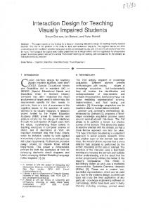
Framework overview Figure 1 illustrates the general platform architecture of our prototype. For input, the system platform uses either a video of a 3D map or a still image of a conventional 2D map. The system’s output can be either a virtual replica of the 3D map or a haptic-aural representation of the 2D map. We divide the processing system into three subsystems: ❚ 3D map video processing, ❚ 2D map image processing, and ❚ haptic rendering of the resulting virtual representations of either the 3D maps or the 2D maps. The 3D-map video-processing module integrates structure from motion algorithms2 to approximate the 3D structure of captured scenes, which leads to 3D map model generation. The second module uses efficient image processing methods such as segmentation, edge detection, optical character recognition (OCR), and text to speech, for example, to build a pseudo-3D representation of the 2D map that a visually impaired person can efficiently perceive (see the sidebar, “Generating Pseudo-3D Representations from Conventional Maps” on page 64). Both subsystems relate directly to the haptic rendering subsystem module, which also provides the interface between the virtual maps and the visually impaired user.
Published by the IEEE Computer Society
Using Haptic Data with Visual Impairment Haptic interaction is especially important to populations with disabilities such as the visually impaired1 because tactile interaction is one of the most important modalities they use to perceive the world. For example, blind users can use haptic interaction recognition of 3D virtual objects, navigation in virtual environments, cane simulation and training, and so on.1 In recent years, there’s been a growing interest in developing haptic interfaces that let users access information presented in 3D virtual reality environments.2 A particularly challenging issue to researchers in the haptic interaction field is generating haptic feedback based on visual data analysis. Shi and Pai, for example, presented a method to generate 2 degrees-of-freedom (DOF) force feedback from models reconstructed from stereoscopic images.3 La Torre et al. proposed a system for haptic access to 3D data obtained using ultrasound images.4 McDaniel et al., meanwhile, introduced a methodology to benchmark algorithms that estimate haptic features from visual images.5 Their methodology is the first reliable evaluation framework of visiohaptic conversion techniques. Our method differs from other researchers’ because it uses as input a monoscopic image sequence and directly generates the resulting force field that actually corresponds to a haptic representation of the reconstructed 3D scene. In the main text, we describe a prediction-correction scheme for generating a
haptic representation of a 3D scene captured from video. After capturing a scene with a simple camera, we apply the predictioncorrection scheme, which uses structure from motion (SfM) techniques and implicit surface approximation to estimate the maps’ structure. We then recursively refine the resulting dense 3D force field and use the force field directly for haptic rendering without having to perform time-consuming collision detection tests.
References 1. D. Tzovaras et al., “Design and Implementation of Haptic Virtual Environments for the Training of Visually Impaired,” IEEE Trans. Neural Systems and Rehabilitation Eng., vol. 12, no. 2, 2004, pp. 266-278. 2. G.C. Burdea, Force and Touch Feedback for Virtual Reality, WileyInterscience, 1996. 3. Y. Shi and D.K. Pai, “Haptic Display of Visual Images,” Proc. Virtual Reality Ann. Int’l Symp. (VRAIS), IEEE CS Press, 1997, pp.188-191. 4. B. La Torre et al., “The Fetouch Project,” Proc. Int’l Conf. Robotics & Automation (ICRA), IEEE CS Press, 2003, pp. 1259-1263. 5. T. McDaniel et al., “A Methodology to Establish Ground Truth for Computer Vision Algorithms to Estimate Haptic Features from Visual Images,” Proc. IEEE Int’l Workshop Haptic, Audio & Visual Environments (HAVE), IEEE Press, 2005, pp. 94-99.
Processing Input
Output
3D-map video processing Structure from motion
Segmentationmotion estimation
3D virtual representation
Haptic devices Video of 3D maps Haptic rendering
Phantom
Virtual model of the 3D map
CyberGrasp
2D-map image processing Still images of conventional maps
Roads and buildings recognition
Haptic representation of 3D maps Generating a virtual replica of a 3D map model captured from a video is a special case of a wellknown, extensively addressed yet still unsolved problem, namely the reconstruction of a 3D scene using only a monoscopic video as input.2,3 Figure 2
Correspondence between roads and their names
3D pseudomap generation
3D representation of the 2D map
(next page) illustrates a conceptual diagram of our proposed method, which uses implicit surface approximation and a prediction-correction procedure to recursively refine, frame by frame, the accuracy of a 3D virtual representation and resultant haptic rendering. We use scene structure esti-
Figure 1. Architecture of the proposed system.
63
Generating Pseudo-3D Representations from Conventional Maps An alternative to the force-field haptic rendering technique for generating navigational aids for the visually impaired, which we’ve described in the main text, is a pseudo-3D representation of a conventional map. This alternative is useful when conventional maps are the data source, rather than a video of a 3D scene. The method for generating such a map for haptic-aural navigation is highly efficient. Factors to consider, in comparing the 2D with the 3D approach, are as follows: ❚ The 3D approach generates a force field that corresponds to a realistic replica of the captured scene in all three dimensions. ❚ The 2D approach generates a conceptual 3D representation in which streets and buildings have different heights, and other map elements are separated using haptic texture and friction. 3D pseudomap generation
— The 3D approach requires sophisticated computer vision algorithms, while the 2D approach needs only simple state-of-the-art image processing techniques. — While the 3D approach generates virtual duplicates of existing scenes, the 2D approach generates pseudo-3D map data that are better suited for navigation purposes. To generate a pseudo-3D representation of a conventional map requires converting the encoded information into a haptic-aural format that visually impaired people can perceive, which further requires an initial step to define the properties of the virtual map. To define a map’s properties, we recommend the following: ❚ Streets are separated from buildings using larger height for buildings in the 3D representation.
(1) After morphological filtering 1
(4) Pseudo-3D map – Grooved line map
OCR-TTS (2) After morphological filtering 2
(3) After postprocessing
Figure A. Architecture of the 2D pseudomap generation system. OCR-TTS stands for optical character recognition-text-tospeech synthesis.
For each new frame First frame
Scene structure estimation
Force field correction Final field correction
3D model prediction
Figure 2. Conceptual diagram of the proposed system.
64
3D model correction
Force field prediction
mation to correct the predictions of both the 3D models and the force field. Our concept is to exploit the advantages of scene structure estimation in terms of accuracy. We can thus avoid the presence of noise or the
generation of open surfaces with missing parts, which would result if we used the structure estimation directly to build a 3D model of an observed scene. Therefore, we initially use a direct prediction of the 3D model using parametric implicit surfaces and define surface parameters using the measurements obtained from scene structure estimation. As a second step, we generate the force field from the generated parametric 3D model and refine it again recursively. This procedure, repeated iteratively frame by frame, results in incremental accuracy of the 3D representation and the generated force field. Figure 3 details the architecture of this module. The module input is the captured video. We
❚ Identify crossroads and special areas (for example, churches and roundabouts).
❚ Names should lie inside the corresponding street. ❚ Crossroads are identified by haptic texturing.
C. Street name recognition: We can generate a pseudo-3D map using simple operations like morphological filtering, state-of-the-art algorithms for image processing, and off-the-shelf systems for optical character recognition and text-to-speech (TTS) synthesis. Figure A illustrates the architecture of a 2D pseudomap system as well as its intermediate results. The system’s input is a conventional 2D map. The output is a pseudo-3D representation of the map with indexing information about street names— that is, buildings are represented with larger height than streets so that a user wearing a haptic device can easily perceive the difference. The name of each street is available and is reproduced in audio whenever the user crosses it. Moreover, the system uses special effects like haptic texturing and friction to distinguish crossroads, and special buildings such as churches, from the map’s main components (streets and major buildings). Briefly, here are the steps to generate a pseudo-3D representation:
❚ Morphological filtering. Apply erode filter and decrease color depth to discriminate the image areas with street names from the rest of the map (see Figure A2). ❚ Estimate the direction of the street names using a linear least-squares method. Match the names and their directions with the segmented map of the second step under “B. 3D model generation.” ❚ Delete names that don’t correspond to streets (see Figure A3). ❚ Perform OCR of the remaining street names. D. Runtime operations: ❚ Collision detection and haptic rendering.
A. Input: Capture still image of the 2D map. ❚ Haptic texturing and friction simulation of the crossroads and the special areas of fourth bullet under “B. 3D model generation.”
B. 3D model generation: ❚ Morphological filtering. Apply dilate filter, thresholding, and median filtering to the input map to discriminate the streets from the major buildings. ❚ Recursively smooth the resulting map to delete fragmented small areas (see Figure A1). ❚ Generate the 3D model (see Figure A4).
3D virtual map generation
Input
❚ Text from speech synthesis to provide aural feedback of the street names while the user navigates into the map using the haptic device. E. Output: A 3D representation of the 2D map, including information about the names of the street, which is displayed using TTS synthesis.
Video processing Occlusion handling
Final force field
Segmentation
Structure estimation
Force field correction
Superquadric approximation
Fitting the superquadric to the obtained 3D data
Force field prediction
Image sequence
January–March 2007
Feature tracking
Figure 3. Conversion of a monoscopic video (image sequence) into a force field.
65
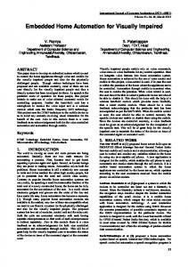
Figure 4. Superquadrics with (a) �1 � 0.2, �2 � 0.2, (b) �1 � 0.2, �2 � 0.9, and (c) �1 � 0.2, �2 � 1.8.
(a)
(b)
can divide the processing into video processing (which corresponds to the scene structure estimation block in Figure 2), and 3D reconstruction (which comprises superquadric approximation, fitting the superquadric to the 3D data, force field prediction, and force field correction). Force field correction yields the final force field. Video processing Video processing uses the captured video as input and generates an estimate of the scene structure accompanied by its segmentation map. We identify rigid objects in the scene initially by a segmentation method3 that uses a kmeans approach with connectivity constraints for defragmentation. Using texture sharpness criteria, we extract reliable features for each object in the first frame and track them to the final frame using an optimized Kanade-LucasTomasi (KLT) feature tracker.4 Next, we estimate 3D motion and structure for the tracked features using a layered approach based on extended Kalman filters.3 When trying to estimate a scene’s structure from a monoscopic image, we encounter problems in handling occluded areas. What we propose is to apply a noncausal probabilistic method to handle occlusion3 to generate a more complete representation of the scene structure. Consequently, we obtain information also for scene parts visible only in a limited number of frames in the captured video.
IEEE MultiMedia
Superquadric approximation In superquadric approximation—a technique for modeling objects as input, range images, and depth maps5—we use analytical implicit surfaces to model the information about the scene structure that we obtained from the video processing. Figure 4 shows an example of superquadrics. Equation 1 defines these superquadrics.
66
(c) ε2 ⎛ ⎞ 2 2 2 ε ⎜ ⎛ ⎛ x ⎞ ε 2 ⎛ y ⎞ ε 2 ⎞ 1 ⎛ z ⎞ ε1 ⎟ F ( x , y, z ) = ⎜ ⎜ ⎜ ⎟ + ⎜ ⎟ ⎟ + ⎜ ⎟ ⎟ ⎜ ⎜⎜ ⎝ a1 ⎠ ⎝ a2 ⎠ ⎟⎟ ⎝ a3 ⎠ ⎟ ⎠ ⎟ ⎜⎝ ⎠ ⎝
ε1
=1
(1) Equation 1 is commonly called an inside-outside function, because for a 3D point (x,y,z): ❚ If F(x,y,z) � 1, then point (x,y,z) lies outside the surface. ❚ If F(x,y,z) � 1, then point (x,y,z) lies inside or on the surface. We can add deformation parameters, such as tapering or bending,5 to the implicit equation to produce a more flexible model. Modeling (approximating) a 3D object with superquadrics is actually a least-squares minimization of Equation 1 with respect to several shape parameters, which we achieve with the well-known Levenberg-Marquardt nonlinear least-squares minimization method. In the context of our proposed method, we start with a rough superquadric approximation of a scene using only the segmentation map that we obtained after the video processing’s initial phase. The approximation in this phase is accurate alongside the axes of the image plane but not alongside the depth axis. Next, using the structure estimates we subsequently obtained for each frame of the initial video sequence, we refine the superquadric approximation of the scene until the final frame is reached and maximum accuracy achieved. This simple yet robust procedure lets us achieve ❚ scene approximation with closed surfaces, ❚ robustness in the presence of structure estimation noise, and
❚ approximation of the scene objects using analytical surfaces.
Figure 5. Illustration of a superquadric and the resulting force field.
It’s important to achieve these conditions before generating the final force field, which we describe next. Haptic rendering: Force field estimation/ refinement We use the extracted 3D scene model to perform haptic rendering. Considering that the scene consists of several superquadrics, we could perform haptic rendering using state-of-the-art methods for detecting collision and calculating force feedback.6 But the simplicity of such an approach is offset by two major disadvantages: ❚ The superquadric approximation doesn’t produce precise approximations of the 3D objects. ❚ Collision detection, which is a computationally intense procedure, must be performed, which decreases the haptic loop’s refresh rate. Notice that during one haptic loop all necessary operations for haptic rendering are performed. The faster these operations are executed, the higher is the refresh rate of the haptic loop, thus resulting in high-fidelity haptic rendering. In our approach, we recursively adapt the scene’s superquadric representation into an estimated 3D data structure. We define a dense 3D grid (or force field) to store the force values for each sampled voxel of the 3D virtual space. As a result, there’s no need to perform collision detection during runtime because the force for each voxel is a priori known. We describe the algorithm’s four steps next: initialization, force field prediction, force field correction, and force magnitude.
Force field prediction. Initially, as Figure 3 illustrates, we approximate the force field F directly from the obtained superquadric approximation (see Figure 5). We can cluster the points of Q into two sets that must be considered separately. ❚ Points outside the superquadric surfaces Qout. ❚ Points inside the superquadric surfaces Qin. For all Qin we calculate the direction of force feedback using our approach to haptic rendering directly from the superquadric approximation. To achieve this we need to obtain, besides the distance of each surface point from the superquadric, the corresponding minimum distance point m on the superquadric, as Figure 6b (next page) shows. Finally, the force feedback stored in the force field is the normal vector of the local surface at point m. For the Qout points, no vector in the force field is assigned. We can use the predicted force field as is for haptic rendering; however, we’ve added a correction step to refine it and generate more accurate force feedback. Force field correction. Next, the force field is corrected using the structure estimates we obtained from the video processing module. The structure estimates are in fact the 3D trajectories of the feature points (that is, the 2D trajectories of the feature points accompanied by a depth value for each frame). Initially, we build a mesh of these points for each scene object using Delaunay triangulation.
January–March 2007
Initialization: Problem formulation. We define as a discrete force field F the result of the �� � �� mapping of a dense quantization Q of the 3D space into a 3D vectorial space H that represents the direction of the resulting force at each point of the quantized 3D space. In other words, F(x) represents the force that should be exerted on an element (such as a haptic device pointer, for example) that lies on x, where x Q and F(x) H. Let us also assume D to be a distance field,7 which corresponds to a �� � � mapping of the same quan-
tization Q of the 3D space into scalar values that represent the signed distance of the points of Q from the superquadric surface SSQ. Positive and negative values correspond to points outside and inside the implicit surface respectively. We calculate D during the initialization step, using Osher and Fedkiw’s methods.1
67
Qout: Outside point Outside SM: Delaunay triangulated mesh SM
Force field direction
SSQ Point “m” SSQ
Qin: Inside point Inside
Inside (a)
(b) Force field vectors Qout: Outside point
Qin: Inside point
SM SSQ
S'SQ
N area
SSQ _M: Projection area of the SM
(c) Figure 6. Force field correction procedure. (a) Superquadric surface (SSQ) and reconstructed surface (SM).The space is divided into points inside and outside SSQ. (b) Estimated direction of the force field. (c) Projection of SM onto SSQ. (d) Backprojection of the SSQ_M surface onto SM. The green arrows illustrate the values of the resulting force field.
68
N area
SSQ surface adapted to SM
(d)
Consider Figure 6a where SSQ represents the superquadric surface and SM the surface obtained directly from the structure estimates. We divide SM into the local surfaces that lie outside and those that lie inside the superquadric. Next, we need to update the superquadric surface in addition to the estimated surface. First, let’s look at the case where surface SM lies outside the superquadric, as Figure 6c shows. Initially, we have to define which points of Q are outside and which are inside the new structure, thus also defining the adapted surface. To do this, we sample the surface of the superquadric. Next, we project SM onto the superquadric, which generates a surface SSQ_M. The superquadric samples that lie inside SSQ_M (consider them as members of set W) are now projected onto the SM. Since surface SM is generally not uniform but has irregularities and holes, projecting the W samples to SM creates steep edges in the areas where a sample is a member of W but its neighbor isn’t, as Figure 6c shows. To avoid this defect, we define the transitional area N as:
N=
∪{ y ∈S
SQ
i
}
y ∉ W,GD (x i , y) < δ , ∀x i ∈ W (2)
where GD(x,y) is the geodesic distance of point x from y and an experimentally selected threshold. All points in N follow the translation of point x weighted by a factor inversely proportional to GD(x,y). Since point y is influenced by more than one point x W, all corresponding translations are averaged. This procedure actually adapts the superquadric surface to the data obtained, as Figure 6d shows. In the final step, we also adapt the force field to the new surface, exactly as we did before for the superquadric but this time using the adapted superquadric one as the input mesh. The only difference is that we use only the points of Q that lie inside the bounding volume of the adapted surface to refrain from the time-consuming processing of all points in set Q. Finally, we apply force shading8 in the resulting force field to generate smoother force transitions on the surface.
Force magnitude. The processing we’ve described thus far results in calculating the force feedback direction, which is also the most difficult task. We use a spring model to calculate the force feedback’s magnitude. In particular, for a point z that enters the surface, the magnitude of the applied force is ��F�� � k d, where k is the elasticity constant and d the distance of z from the surface obtained from the distance field D. Summarizing the final force feedback for a point z �� that corresponds to a point x Q, we can calculate it as follows: Fhaptic � k D (x) F (x), where D(x) and F(x) are the value and the vector stored in the distance and force field, respectively. Our haptic rendering scheme features 6 DOF that degrades to 3 DOF when we use SensAble Technologies’ Phantom Desktop device (see http://www.sensable.com) or to 5 DOF when we use Immersion’s CyberGrasp (see http://www. immersion.com)—1 DOF for each finger. Our scheme is superior compared to existing 2-DOF techniques9 because it’s consistent with physical laws and generates realistic force feedback, unlike surface properties mapped to the force felt by users.9 Memory management Our method’s efficiency—for generating a force and a distance field to rapidly perform haptic rendering, without needing to perform collision detection during runtime—carries a price tag: our framework requires significant memory to store the force and distance field. To handle floatingpoint arithmetic, the required memory to store the force and distance field for accurate haptic rendering would be about 2 gigabytes (GB). This value would make our algorithm inefficient; therefore, we adopted Frisken et al.’s adaptively sampled distance field scheme10 and applied it in our framework to both the distance and the force field. We observed that this approach can significantly reduce the memory requirements by as much as 95 percent. For storage purposes, we used the LempelZiv method for losslessly compressing the data.11
We tested our force field method by haptically rendering two 3D map models. In both cases, we used SensAble Technologies’ Phantom Desktop device. Applications and experiments Figure 7 shows our results with the first model, which involved the exterior of two buildings and
(b)
(c)
(d)
(e)
(f)
Figure 7. Final and intermediate results of the first 3D map model that we converted into a force field. (a) and (b) show two different perspectives of the captured map model. (c) Scene structure estimation (depth map). (d) The superquadric approximation generated as a result of the least-squares fit of the superquadrics on the depth map of Figure 7c. (e) The refined 3D approximation of the model after the force-field correction procedure. (f) A zoom view inside the red rectangle to highlight the modifications of the correction procedure.
a corresponding outdoor area at Thessaloniki’s international exhibition center. Figure 7c illustrates the depth map generated by the video processing module for the first model. Higher values of intensity correspond to areas that are closer to the camera. Figure 7d depicts the final superquadric approximation of the obtained 3D structure data after the recursive refinement of the superquadric parameters. Finally, Figures 7e and 7f show the final 3D model following force-field refinement.
January–March 2007
Experimental results
(a)
69
(a) Figure 8. (a) Captured map model. (b) Scene structure estimation (depth map). (c) Scene 3D approximation after the force-field correction procedure.
(b) Memory requirements for storing the force and distance field for our first experiment was 2 GB for fine sampling of the 3D space. We were able to reduce the memory to 122 megabytes (MB) through the adaptively sampled distance and force fields. 10 By applying the compression method we described previously, we further reduced the memory requirements to 11.5 MB. Figure 8 shows our haptic rendering results with the second model, which was a block of buildings in Thessaloniki’s suburbs. For this experiment, we captured another map model from its top view as Figure 8a shows. In this case, the structure estimates produced a limited number of depth levels, as Figure 8b shows, because the depth variation for the buildings isn’t very large. Figure 8c illustrates the 3D approximation result of our proposed scheme. For this experiment, we needed 93 MB to store the adaptively sampled distance and force field, but we later reduced this to 7.9 MB with compression.
IEEE MultiMedia
Evaluation Our proposed system underwent tests with 19 users—from the Local Union of the Panhellenic Association of the Blind in Thessaloniki, Greece— who evaluated our force-field rendering system according to tasks we devised. They explored the maps in exocentric reference frames, where the viewpoint of the observer is extracted from the virtual environment. Although exploration in egocentric reference frames—frames where the viewpoint of the virtual environment corresponds to the viewpoint of the observer as if he/she was immersed within the scene—is possible in our framework, the evaluation was performed with exocentric reference frames because they provided a better basis for the navigation and object recognition tasks conducted in our experiments. In addition, our method transforms
70
(c) the pseudo-3D maps into grooved-line maps (see Figure A4 in sidebar) that are more efficient when used for haptic interaction.12 We designed the evaluation to help assess the qualitative and quantitative estimation of ❚ overall usability of the proposed framework to nonspecialized individuals, and ❚ acceptance of the tools, user friendliness, and points where it needed improvement. We defined two tasks for the blind users to perform. The first task was to go from a specific point of the pseudo-3D map (red point in Figure A4 in the sidebar) to another location in the map (green point in Figure A4). Initially, we gave aural instructions to the users about the route they were to follow before they began the task. The second task was to identify objects of the scene in Figure 7d and place real boxes in relative positions as they appear in the 3D environment. The test procedure consisted of two phases: In the first phase, users were introduced to the system and asked to use it. They were also asked questions that focused on usability issues and on their interest in participating in the test. The questionnaire we used contained questions for the test observers: for example, if the user performed the task correctly, how long did it take him or her to perform the task? The second phase was carried out immediately after the tests, using another questionnaire. Specifically, we questioned users about general issues such as the benefits and limitations that they foresee with this technology, and the usability of the system for navigation. The system evaluation results showed that users considered our system innovative and satisfactory in terms of providing an alternative tool for exploring 3D maps. The ANOVA analysis of
the results showed no significant difference between male and female users—F(1, 17) � 1.02; p � 0.05; 9 male and 10 female. Moreover, the results showed no difference between users who were blind from birth and those who became blind at a later age—F(1, 17) � 0.81; p � 0.05; 8 were blind from birth and 11 were blind at a later age. Users familiar with haptic interfaces (the ones who had participated in earlier tests by Tzovaras et al.7) performed better than users who weren’t—F(1, 17) � 8.3; p 0.05; 10 were familiar and 9 weren’t familiar. In general, all users were satisfied. They mentioned that they would prefer a pseudo-3D grooved-line map to explore a large-scale area and a 3D representation of a small-scale environment to better investigate its details. They concluded that the ideal system would integrate both 3D and pseudo-3D representations in which users could zoom in to specific areas of the pseudo3D map and to further investigate that area’s 3D representation.
Conclusions
This work was supported by the European Commission�funded SIMILAR IST [The European task force creating human–machine interfaces SIMILAR to human–human communication; Information Society Technologies] Network of Excellence (FP6-507609) and the Greek Secretariat for Research and Technology�funded projects APEIRO [Interactive Presentation and Simulation of Ancient Greek Technologies] and VRLab [Virtual Reality Laboratory].
References 1. S.J. Osher and R.P. Fedkiw, Level Set Methods and Dynamic Implicit Surfaces, Springer-Verlag, 2002. 2. T. Jebara, A. Azarbayejani, and A. Pentland, “3D Structure from 2D Motion,” IEEE Signal Processing, vol. 16, no. 3, 1999, pp. 66-84. 3. K. Moustakas, D. Tzovaras, and M.G. Strintzis, “Stereoscopic Video Generation Based on Efficient Structure and Motion Estimation from a Monoscopic Image Sequence,” IEEE Trans. Circuits and Systems for Video Technology, vol. 18, no. 5, Aug. 2005, pp. 1065-1073. 4. J. Shi and C. Tomasi, “Good Features to Track,” Proc. IEEE Int’l Conf. Computer Vision and Pattern Recognition, IEEE CS Press, 1994, pp. 593-600. 5. F. Solina and R. Bajcsy, “Recovery of Parametric Models from Range Images: The Case for Superquadrics with Global Deformations,” IEEE Trans. Pattern Analysis and Machine Intelligence, vol. 12, no. 2, 1990, pp. 131-147. 6. Y. Shi and D.K. Pai, “Haptic Display of Visual Images,” Proc. Virtual Reality Ann. Int’l Symp. (VRAIS), IEEE CS Press, 1997, pp.188-191. 7. D. Tzovaras et al., “Design and Implementation of Haptic Virtual Environments for the Training of Visually Impaired,” IEEE Trans. Neural Systems and Rehabilitation Eng., vol. 12, no. 2, 2004, pp. 266-278. 8. D.C. Ruspini, K. Kolarov, and O. Khatib, “The Haptic Display of Complex Graphical Environments,” Computer Graphics, Siggraph 97 Conf. Proc., 1997, ACM Press, pp. 345-352. 9. B. La Torre et al., “The Fetouch Project,” Proc. Int’l Conf. Robotics & Automation (ICRA), IEEE CS Press, 2003, pp. 1259-1263. 10. S.F. Frisken et al., “Adaptively Sampled Distance Fields: A General Representation of Shape for Computer Graphics,” Proc. Int’l Conf. Computer Graphics and Interactive Techniques (Siggraph 2000), ACM Press, pp. 249-254. 11. J. Ziv and A. Lempel, “A Universal Algorithm for Sequential Data Compression,” IEEE Trans. Information Theory, vol. 23, no. 3, 1997, pp. 337-343.
January–March 2007
One of the major and challenging issues for the haptics community is the cross-modal transformation of visual into haptic data. The approach we’ve described in this article presents an efficient framework for converting moving images of map models directly into hapticsperceivable data for training the visually impaired. Experimental results have shown that the system is capable of providing all necessary means for navigating in virtual replicas of 3D map models or conventional maps using offthe-shelf haptic devices. A challenging extension of the proposed approach is the real-time, dynamic haptic interaction with a video sequence, where the user will be able perceive the video sequence via the sense of touch. This problem is more general than the one presented and requires high accuracy in the 3D reconstruction step to produce high-fidelity force fields. Another challenging extension of our approach would also be to convert satellite image sequences into 3D, thus providing an automated way to generate global maps. As an alternative to our proposed force-field haptic rendering system, we described a method to generate pseudo-3D maps from conventional 2D maps that has produced highly accurate conceptual representations. Which of these two methods should a prospective user choose? It depends only on the available input data. MM
Acknowledgments
71
12. R. Ramloll et al., “Constructing Sonified Haptic Line Graphs for the Blind Student: First Steps,” ACM Conf. Assistive Technologies, ACM Press, 2000. Konstantinos Moustakas is a PhD candidate in Aristotle University of Thessaloniki, Greece, and a research fellow in the Informatics and Telematics Institute, Thessaloniki. His main research interests include virtual reality, collision detection, haptics, deformable object modeling and simulation, computer vision, and stereopsis. He received a diploma in electrical and computer engineering from Aristotle University of Thessaloniki, Greece, in 2006. Georgios Nikolakis is a research engineer at the Informatics and Telematics Institute, Thessaloniki, Greece, which he joined in 2000. His research interests include human–computer interaction, assistive technologies, and hap-
Coming in December 2006
FREE Visionary Web Videos about the Future of Multimedia. Listen to premiere multimedia experts! Post your own views and demos!
tic interfaces. He received a diploma in electrical engineering from the Electrical Engineering Department, and an MSc in medical informatics from the Medical School, both from Aristotle University of Thessaloniki. Konstantinos Kostopoulos is a research fellow in the Informatics and Telematics Institute, Thessaloniki, Greece. His main research interests include pattern recognition, digital image processing, and 2D digital filters. During the past two years he has worked on image processing and 3D haptic maps. He received a diploma in electrical and computer engineering from Aristotle University of Thessaloniki, Greece, in 2006. Dimitrios Tzovaras is a senior researcher in the Informatics and Telematics Institute, Thessaloniki. His main research interests include virtual reality, assistive technologies, 3D data processing, and stereo and multiview image sequence coding. Tzovaras is an associate editor of the EURASIP Journal of Applied Signal Processing. Tzovaras received a diploma in electrical engineering and a PhD in 2D and 3D image compression from Aristotle University of Thessaloniki, in 1992 and 1997, respectively. Michael G. Strintzis is a professor of electrical and computer engineering at the Aristotle University of Thessaloniki and, since 1999, is director of the Informatics and Telematics Research Institute, Thessaloniki. His current research interests include 2D and 3D image coding, image processing, biomedical signal and image processing, and DVD and Internet data authentication and copy protection. Strintzis has served as associate editor for the IEEE Transactions on Circuits and Systems for Video Technology since 1999. An IEEE Fellow, in 1984 he was awarded an IEEE Centennial Medal.
IEEE MultiMedia
Readers may contact Michael Strintzis at strintzi@ eng.auth.gr.
Visit www.computer.org/multimedia
For further information on this or any other computing topic, please visit our Digital Library at http://computer. org/publications/dlib.
72