with a Time-of-Flight and Haptic Feedback Device ... The system provided a speed advantage in steering a blind .... Vibration units placed on the back of a.
TRANSACTIONS ON NEURAL SYSTEMS AND REHABILITATION ENGINEERING
1
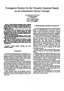
Safe Local Navigation for Visually Impaired Users with a Time-of-Flight and Haptic Feedback Device Robert K. Katzschmann, Member, IEEE, Brandon Araki, Member, IEEE, and Daniela Rus, Fellow, IEEE
Abstract—This paper presents ALVU (Array of Lidars and Vibrotactile Units), a contactless, intuitive, hands-free, and discreet wearable device that allows visually impaired users to detect low- and high-hanging obstacles as well as physical boundaries in their immediate environment. The solution allows for safe local navigation in both confined and open spaces by enabling the user to distinguish free space from obstacles. The device presented is composed of two parts: a sensor belt and a haptic strap. The sensor belt is an array of time-of-flight distance sensors worn around the front of a user’s waist, and pulses of infrared light provide reliable and accurate measurements of the distances between the user and surrounding obstacles or surfaces. The haptic strap communicates the measured distances through an array of vibratory motors worn around the user’s upper abdomen, providing haptic feedback. The linear vibration motors are combined with a point-loaded pretensioned applicator to transmit isolated vibrations to the user. We validated the device’s capability in an extensive user study entailing 162 trials with 12 blind users. Users wearing the device successfully walked through hallways, avoided obstacles, and detected staircases. Index Terms—Assistive Device, Sightless Navigation, HumanRobot Interaction, Perception, Haptic Feedback Array
I. I NTRODUCTION ISUAL impairment affects approximately 285 million people worldwide, of which 39 million are blind, and 246 million have moderate to severe visual impairment [1]. Estimates suggest that another person in the world goes blind every 5 s [2]. This is a large number of people who rely on a combination of their other senses—hearing, touch, and even smell—and tools like walking sticks and helpers like guide dogs to alert them to obstacles. White canes are a simple, robust solution for local navigation and obstacle avoidance. However, white canes have several flaws. They are often stigmatized, require physical exertion, occupy one hand, need physical contact with the environment, and can only detect obstacles by point contact at heights up to the users’ chests. This paper proposes that mechanical feedback coupled to sensor technology as well as perception and planning algorithms is a potential solution to enable people with visual impairments to navigate their environment discreetly and effortlessly. This solution is not an attempt to recreate sight, but to process sensor information into useful navigational information that the user can rely on to create a mental map of their surroundings. Embedding small and lightweight sensors along with haptic devices in clothes allows for seamless integration of wearable navigation technology into the lives of visually impaired people.
V
All authors are with the Distributed Robotics Laboratory, Computer Science and Artificial Intelligence Laboratory, MIT, 77 Massachusetts Avenue, Cambridge, MA 02139, USA, e-mail: {rkk,araki,rus}@csail.mit.edu. Manuscript received Mar 3, 2017.
Fig. 1. ALVU in Action: A visually impaired person wearing the sensor belt and haptic strap is experiencing distances to the surrounding environment via haptic feedback on the upper abdomen while walking through a confined space. The green and red cones indicate the view of each sensor, a cone is shown in green when the view of the sensor is unobstructed and a cone is shown in red when it is detecting an obstacle.
There have been several works that proposed steps towards such a solution. For example, one study reported the design of a handheld device with two infrared sensors combined with audible and vibratory feedback [3]. However, users were not comfortable using the device in place of a white cane and the device was not successful in preventing collisions with the environment. In a different study, the data from a stationary laser scanner steered a user through a room using several vibration motors, but a long response time of 1.9 s was reported with this immobile scanner [4]. Such a long response time made the system inadequate for real-time navigation feedback. Another study reported the use of a depth camera and a neural network to detect free space, obstacles, and stairs. This system was not designed to be portable, to work outdoors, or to provide a feedback mechanism to the user [5]. A related study mounted a depth camera to glasses, which was used to build up an occupancy map; four distinct navigation cues were used as output, displayed on a tactile feedback vest [6] [7]. The system provided a speed advantage in steering a blind user through the map only when used in conjunction with a white cane; additionally, the system did not provide local obstacle detection. Furthermore, the system was not compact and portable. In another study, a walker equipped with two laser scanners, a computer, and one vibration motor in each handle enabled a user to navigate through an environment while holding on to the walker [8]. We recently showed an alternative approach to the problem using a wearable depth camera [9] and also implemented the algorithms in that work on a low-power vision processor [10]. Overall, the prior work
TRANSACTIONS ON NEURAL SYSTEMS AND REHABILITATION ENGINEERING
has not shown a complete solution to local obstacle avoidance that is a long-lasting, end-to-end system a blind user can wear to receive reliable local navigation clues. Furthermore, the gold standard for validation of a system should be actual user testing with people with visual impairments, which most of the studies discussed above did not provide. Our objective is to create a contactless, intuitive, hands-free, and discreet wearable local navigation solution that allows users to sense both low- and high-hanging obstacles as well as physical boundaries in their immediate environment for local navigation. We create a miniaturized and wearable time-offlight sensor array that has a wide-angle view both horizontally and vertically. Its processed output is communicated to the user through a wearable haptic feedback array. Our system, called ALVU (Array of Lidars and Vibrotactile Units), provides feedback from multiple directions at the same time to enable the user to identify free space. Figure 1 shows our system in action. We validated our solution through user studies with subjects who were totally blind. Our system enables people who are totally blind to complete key activities that they normally perform with a white cane in a similar amount of time, while providing the benefits described above. II. R ELATED W ORK This research builds on important related work on (1) assistive technologies and (2) autonomous navigation. An important technical component is the algorithmic solution to local obstacle detection and the hardware platform for sensing, which includes components such as infrared sensors, sonar (sound navigation and ranging), lidar (light detection and ranging), and RGB-D (Red, Green and Blue - Depth) cameras. The most relevant work is already mentioned in the introduction: it shows systems with on-board computation that are evaluated for mobility tasks through user studies with blind-folded and/or visually impaired subjects [3]–[10]. A. Reviews and Surveys A broad review of assistive technologies for the blind [11] covered output devices such as braille displays for the feet, fingertips, wrists, forearms, tongue, and head; while promising, these devices were also bulky and often invasive. Tactile vests, belts, and audio representations were also covered in [11]; however, they were either very bulky, did not provide information on local obstacles, did not offer haptic feedback, or were not tested in a user study with blind people to back up the authors’ claims. A comparative survey among portable/wearable obstacle detection/avoidance systems in [12] outlined the capabilities of these systems by providing qualitative-quantitative measures. The review by [13] highlighted the importance of involving visually impaired users in all phases of the assistive device development and the need for appropriate blind user interfaces. A review by [14] described assistive computer vision technologies using RGBD cameras for blind and visually impaired people; the authors concluded that a complete solution had yet to be offered. A review of the SmartCane, UltraCane, iCane, GuideCane,
2
and K-Sonar systems was provided in [15]; all solutions were mounted to a white cane and only covered a single sensing direction. B. Sonars and Cameras The SmartCane [16] and the UltraCane/Batcane [17] [18] were systems that fully relied on a white cane and only used a single sonar sensor attached to a cane to detect above-knee obstacles in the direction of the cane, signaling this through a vibration. Similarly, a system with a single sonar sensor [19] detected an obstacle at chest height and signaled the user through a vibrating necklace. This system also required the use of a white cane. Tacit [20] was a wrist-mounted device that used a single sonar sensor to relay the distance to an obstacle as a pressure on the wrist, requiring users to move their hand around in order to sense the environment. No tests or user studies were performed to test the efficacy of the device. A collision-warning pendant for users with hemianopsia1 [21] was equipped with a video camera that tracked image features [22] and then signaled impending collisions through distracting audible beeps based on timeto-collision rather than proximity. The system was specifically designed for users that had lost only part of their field of vision and helped to reduce collisions when compared to using no aid at all. The Electronic Mobility Cane [23] was equipped with five sonars mounted along a white cane to sense obstacles and alerted a user via audio or one vibration motor at the handle of the cane. C. Vibrotactile Feedback An overview by [24] compared vibrotactile actuators that can be used in wearable haptic devices. The ActiveBelt [25] mapped GPS (Global Positioning System) directional information to several vibration motors worn around the waist, but no local obstacle information was provided. A head-mounted device by [26] relayed generic information to the user via air puffs to the forehead. 1D and 2D arrays of vibration motors worn around the abdomen provided signals to soldiers [27]. Low frequency Pacinian corpuscle stimulation with up to 128 vibrating elements was used for maintaining a stable hover in helicopters [28]. Vibration units placed on the back of a person potentially widened their field of view within a virtual environment [29]. The haptic interface Force Blinker 2 [30] was a handheld stick that indicated direction by generating a centrifugal force. None of these studies, to our knowledge, performed tests with blind users to verify their effectiveness in a mobility task. III. W EARABLE NAVIGATION S YSTEM We present ALVU, a novel wearable system for safe navigation that is effective at providing a user with detailed feedback about the obstacles and free space surrounding the user. We also describe studies with blind subjects that assessed the performance and effectiveness of our system. 1 Defined
as blindness over half the field of vision.
TRANSACTIONS ON NEURAL SYSTEMS AND REHABILITATION ENGINEERING
3
and low latency communication. Our system’s horizontal field of view is ±70◦ with a possible detection range from 0 m up to 14 m, whereas users do not ask for more than 2.75 m during indoor tests. The front-facing vertical field of view is ±45◦ with a detection range for low or high obstacles starting at a distance of around 0.75 m. ALVU can help users achieve key tasks that are typically performed with white canes. Three such key activities are (i) navigation through a path with boundaries and turns, (ii) detection of and subsequent navigation around obstacles along the path, and (iii) detection of drop-offs (i.e. steps or curbs). A. Design
Fig. 2. Principle of Operation: The schematic shows how a visually impaired person wearing the sensor belt and haptic strap is experiencing distances to the surrounding environment via haptic feedback on the upper abdomen. The person uses the feedback to avoid a wall and to step around a box. In this scenario, the sensor belt is configured to have two downward-facing sensors and five horizontal sensors. In the left panel, the person feels on their right side a wall in close proximity through strong and frequent pulses against their skin. The person also senses in their front a low-height obstacle through a different rhythm of pulses. The person steps to their left, guided by the intensity, rhythm, and presence of the tactile feedback, until the wall is further away and the sensation in the front has cleared. The right panel then shows the person after stepping forward past the wall and box, now feeling a different sensation indicating downward steps.
Specifically, we integrated an array of sensors and feedback motors into a discreet wearable system to create an assistive navigation device for a person with visual impairments. The overall system design involves two parts: A sensor array consisting of distance sensors and a haptic array consisting of feedback units. A user wearing ALVU experiences his or her distance from surfaces/obstacles in his surroundings via feedback from the haptic strap that goes around the upper abdomen. Shorter distances to obstacles are relayed by increased pulse rates with higher vibration strength. For example, when there is an obstacle to the right of the user, he or she feels strong frequent pulses on the right side through the haptic strap. For the user, this leads to the perception of an obstacle to the right. The user can then avoid the obstacle by stepping left. After stepping left, the pulses on the right side stop and the user perceives that there is no longer an obstacle on his or her right side. A more detailed example to describe the principle of operation is depicted in Figure 2. The goal is to integrate this functionality into a discreet wearable system. The sensor belt holds an array of seven time-of-flight sensors aimed towards the front, sides, ground, and ceiling in front of the user (Figure 3-B). The down-facing sensor also has an attitude and heading reference system (AHRS) attached to its back to keep track of the sensor’s pitch, which is important for properly detecting low and high obstacles. The individual sensors are connected together by a single flat ribbon cable that leads to a printed circuit board (PCB) within a pouch at the side of the sensor belt. A microcontroller processes the information triggered by an interrupt and sends it as processed commands in the form of an 8 byte message via a Bluetooth transceiver to the haptic array, also called the haptic strap (Figure 3-A). Focus is placed on an efficient implementation
ALVU consists of two components: sensing the world to create a map, and projecting the map onto the user’s body through haptic feedback. These components can be implemented in various ways and we chose to build them as a sensor belt and a haptic strap. In the following sections we discuss the design of the sensor belt and the haptic strap. We addressed the key challenge of determining the number of vibration units and sensors by assessing the user’s sensitivity and ability to distinguish vibrations sparsely spaced around the abdomen and the user’s desired field of view. 1) Sensor Belt: The free space surrounding a user is computed through the use of distance measurement sensors. Instead of using a rotating laser to create a map of the surrounding, an array of discrete sensors covers the space in front of the user. The design of the belt allows sensors to only be mounted next to each other. However, the quantity, angle, resolution, update rate, and sensing cone remain variables that can be optimized depending on the task. a) Sensor: The choice of sensor technology depends on key variables such as range, coverage, latency, update rate, reliability, sensor size, modularity, and wearability. We use infrared time-of-flight (TOF) distance sensors with a focused field of view, a long range both indoors and outdoors, high accuracy, small size, and low latency. Another alternative is sonar; however sonar sensors are inferior in terms of range, coverage (beam too wide), latency, update rate, and reliability (cross-talk between sonars). b) Placement: We placed the sensor belt below the haptic strap around the waist, where it is relatively discreet and can also function as a regular belt (Figure 4). Another advantage is that the waist is located close to the body’s center of mass and it functions like a hinge for the legs and the upper body, so it moves relatively little while a person is walking, unlike the legs or upper body. This placement avoids obstruction by hands while walking. We also considered a hat as an alternative placement of the sensor array, but fitting more than three sensors in a discreet manner into a gender-neutral hat was not possible. c) Components: The sensor belt holds an array of seven TOF sensors2 , an AHRS3 , a microcontroller4 , a Bluetooth 2 Terabee
Teraranger One: www.teraranger.com/products/teraranger-one 9-DOF Absolute Orientation IMU Fusion Breakout - BNO055, Product ID: 2472 4 mbed LPC1768: developer.mbed.org/platforms/mbed-LPC1768 3 Adafruit
TRANSACTIONS ON NEURAL SYSTEMS AND REHABILITATION ENGINEERING
4
Fig. 3. Feedback and Sensor Belt: (A) shows the haptic strap with the five motor frames mounted on rubber bands and one motor frame is circled in yellow; (B) shows the sensor belt containing seven sensors.
capacity, the sensor belt can operate for 5.5 h before it needs recharging. The sensor belt has a weight of about 480 g, about twice the weight of an average leather waist belt. The elastic strap on the back of the sensor belt allows the belt to be worn by small, medium, and large waist sizes in the range of 65 cm to 130 cm in circumference.
Fig. 4. Wearing the ALVU: (A) shows a front view of a person wearing our system; (B) shows the haptic strap worn underneath the person’s clothing with the front unit circled in yellow.
transmitter5 , and a rotary potentiometer knob for user input. The sensor belt is powered by a lithium-ion battery6 . All components including the battery are integrated into a leather belt and a pouch, shown in Figure 3-B and Figure 4. The length of the sensor belt is adjustable using an elastic strap with buckle that can be secured in the back. The elastic strap is made in three lengths to accommodate for a wide range of waist sizes. The cost of the sensor belt components is ∼$1.3k, with $1k alone for the seven TOF sensors. d) Specifications: The TOF sensors measure distance by emitting pulses of eye-safe infrared light and recording the time it takes for the light to return to the sensor. The sensors measure distances up to 14 m with 0.5 cm resolution and 4 cm accuracy. A single sensor is 31 mm wide and 24 mm high, has a field of view of 3◦ , takes measurements at a rate of 1000 Hz, and weighs 8 g. The sensor works both indoors and outdoors, even under direct sunlight with a decreased range of up to 6 m. The sensors do not interfere with each other. Transparent objects like windows or glass walls are not reliably detected, but a newer generation of the sensor module combines the TOF sensor with a sonar sensor to address this issue7 . The sensors’ small size and overall reliability enables the sensor array to make rapid and reliable distance measurements over a wide field of view. The sensor belt has a rotary potentiometer knob that allows a user to personalize how different distances map to different levels of intensity and pulse rate. With a 24.4 Wh battery 5 JBtek HC-05 Wireless Bluetooth Host Serial Transceiver Module Slave and Master: ijbtek.com/product/html/?54.html 6 ZIPPY Compact 2200mAh 3S 25C Lipo Pack 7 Terabee Teraranger Duo: www.teraranger.com/products/teraranger-duo
2) Haptic Strap: The choice of feedback technology depends on key variables such as intuitiveness of the mechanism, latency, placement on body, modularity, seamless wearable integration, low interference with other human senses, and operational longevity. Feedback from the blind community demonstrates a dislike for audible feedback from the device, due to a preference to use their hearing for freely observing the environment. Electrical stimulation of a user’s tongue [31] was not further considered as a means of feedback, because it is intrusive by inhibiting speech and ingestion, and such a device can not be worn in a discreet manner. Hence, vibratory motors were chosen as the feedback device. The key advantages of vibratory motors are that they provide haptic instead of audible feedback and that they can be placed anywhere on the body. After we assessed the user’s sensitivity and ability to distinguish vibrations sparsely spaced around the abdomen, we decided to place five feedback motors in a linear and horizontal manner along an elastic strap worn across the upper abdomen (Figure 4-B). A single strap around the upper abdomen is sufficient, but if a different haptic feedback is desired, the design allows for several haptic straps to be placed on areas like the chest, the lower abdomen, or the thighs. a) Placement: We chose the placement of the haptic feedback on the upper abdomen for four reasons. First, the upper abdomen is less variable in circumference compared to other parts of the torso. It allows the haptic strap to be worn similarly to a heart rate monitor in close contact to the skin, either on top of an undershirt or directly on the skin. Second, the upper abdomen is also less likely to be squeezed or compressed when sitting or wearing a backpack. Third, a wristband as an alternative placement of the haptic array was considered, but distinguishing more than two vibration units around the wrist was not possible and users felt greatly distracted by vibrations on their wrist when using their hands. Fourth, the designers of the Active Belt [25] and the designers of an array of vibration motors [27] also chose to provide haptic feedback on the upper abdomen of the user.
TRANSACTIONS ON NEURAL SYSTEMS AND REHABILITATION ENGINEERING
b) Spacing: The placement on the abdomen allows for an intuitive mapping of the sensors’ horizontal directions to the feedback motors on the haptic strap. The feedback motors are spaced 8 − 12 cm apart, depending on the person’s upper abdominal circumference. The minimal horizontal separation of feedback motors is defined by the user’s ability to distinguish two vibrations next to each other. Our assessment on a suitable spacing between the feedback motors was confirmed by a detailed study about tactile direction discrimination on the torso [29]. The study reported that two tactile stimuli can be distinguished at best 0.4 cm apart on the frontal side and at worst 3.1 cm at the dorsal side of the torso. c) Components: The haptic strap receives commands from the sensor belt via a Bluetooth transceiver. A microcontroller reads in the messages, processes them, and sends commands to the motor drivers8 of the linear resonant actuator (LRA)9 . The connection from the drivers on the PCB board to the LRAs is done via cables running through an elastic strap. The strap consists of two stretchable layers, with all the wiring between both layers threaded in a zigzag manner. The strap is made in three different lengths, and each length is adjustable using several sewn-in hooks in order to cover different abdominal sizes in the user field. The cost of the haptic strap components is ∼ $150. d) Vibration Specifications: Each vibration unit contains an LRA that vibrates at ∼175 Hz, which falls within the ∼40 − 400 Hz range in which human skin can feel vibration, and lies close to the 200 − 300 Hz range of peak sensitivity [11]. When the LRA is turned on, it vibrates at a constant frequency. To achieve this, the driving circuit employs auto resonance tracking, which automatically detects and tracks the LRA resonant frequency in real time. The key challenge of vibratory motors is the isolation of the vibrations. The use of a pre-loaded small motor frame within a larger casing isolates the vibrations from the area of skin the motor is pushed against. The coin-shaped LRA is embedded in a small motor frame that is mounted on a rubber band (Figure 3-A). Both ends of the rubber band are clamped into a rigid frame, which itself is attached to the stretchable strap worn around the upper abdomen. The strap presses the plastic frame with the LRA inside into the user’s skin by stretching and preloading the rubber band. This design allows the vibration unit to have firm contact with the skin. It also minimizes vibrations wandering off elsewhere along the haptic strap. The time delay between obstacle detection to vibration output is approximately 120 ms.
B. From Sensing to Feedback We developed and implemented algorithms for identifying obstacles in the user’s surroundings, and projecting this information on the body of the user with the haptic strap. In our descriptions, we refer to ToF sensors, but our algorithms are 8 DRV2603 - Haptic Driver with Auto Resonance Tracking for LRA: www.ti.com/lit/ds/symlink/drv2603.pdf 9 Precision Microdrives Linear Resonant Actuators: precisionmicrodrives.com/vibration-motors/linear-resonant-actuators-lras
5
Sensor Belt
Front ToF Measurement
Mid-Left ToF
Mid-Right ToF Right ToF
Left ToF
Low-Pass Filter
Low-Pass Filter
Low-Pass Filter
Low-Pass Filter
Low-Pass Filter
Ellipsoidal Weights Bluetooth Transmission
Haptic Strap Vibration Synchronization
Left Vibration
Mid-Left Vibration
Center Vibration
Right Vibration
Half-Right Vibration
Fig. 5. From Sensing to Feedback: The information flow from sensing to feedback is shown for the horizontal sensing directions of ALVU.
similarly applicable to other sensor types. The flow of information from sensing to feedback for the horizontal sensing directions of ALVU is shown in Figure 5. a) Viewing Angle: A blind user typically walks forward and not sideways. He or she is most concerned with obstacles in his or her path of travel that can cause a fall or injury. A user wants to detect at all heights what is directly in front of him or her: low obstacles, high-hanging obstacles, or drop-offs. A user is less interested in obstacles that are further away to the side. We therefore need a minimum horizontal coverage of up to θ = ±70◦ away from the forward-facing direction of the user. Seven sensors are a suitable amount to cover this range; a higher number is too granular for humans to distinguish. The resolution is defined by the human haptic sensitivity along the upper abdomen. Since the user is turning and moving on a plane and only needs vertical information directly in front, greater coverage in the horizontal rather than vertical dimension is needed. We determined empirically through user tests that viewing low obstacles, high-hanging obstacles, or staircases through only two additional sensors at the angles of φ = ±45◦ is sufficient to get a good coverage in the vertical spread. Therefore, for a total of seven discrete ToF sensors, we allocated two for the vertical resolution and five for the horizontal resolution. The resulting placement of the sensors on the belt at waist height is shown in Figure 4. The sensing cones are shown at scale in Figure 1. b) Sensing Gaps: The small viewing angle of each sensor leads to a discrete separation of the laser beams, with sensing gaps along the whole viewing angle. For the particular system we have built, the sensors give a 3◦ field of view for each laser unit, which leads to a beam width of 10 cm when facing obstacles at a distance of 0.75 m and a beam width of 14 cm when further away from an obstacle at a distance of 1.5 m. However, the user’s forward motion sweeps the
TRANSACTIONS ON NEURAL SYSTEMS AND REHABILITATION ENGINEERING
sensors through space and therefore compensates for those gaps through continuous measurements in time. c) Measurements: The distance measurements running at 1000 Hz are low-pass filtered when queried by the microcontroller at 50 Hz. The AHRS unit uses its internal gyroscope, accelerometer and magnetometer measurements to perform a continuous non-linear estimation of the absolute orientation10 . The microcontroller processes the distance measurements of the ToF sensors together with the absolute orientation measurements of the AHRS and turns the measurements into commands sent via Bluetooth to the haptic strap. d) Ellipsoidal Weighting: The forward motion of a user is typically faster than the sidestepping motion. To augment the distance measurements to accommodate for that fact, the conversion setting for the further away distances towards the front of the user have the same intensity levels as closer distances to the side. The measured distances around the user are weighted and mapped into vibration intensities by an ellipsoidal shape that is smaller to the sides and larger to the front of the user. Additionally, a rotary knob allows the user to adjust the overall scale of the ellipse. Based on initial user tests and user feedback, the ellipsoidal shape is defined by a minimal front range of 0.4 − 1.0 m and a maximal front range of 1.2 − 2.75 m, as well as a minimal side range of 0.2 − 0.5 m and maximal side range of 0.4 − 1.2 m. The distance measurements fall into one of five levels of intensity. The discretized values are then transmitted to the haptic strap. e) Calibration: When the sensor belt is first turned on, it assumes that there is no nearby obstacle or staircase in front of the user. In that moment, the sensor belt calibrates itself by storing the current pitch orientation provided by the AHRS and the initial sensor distance reading by the downfacing sensor as calibration values. Thereafter, the calibration values, the current pitch orientation, and the sensor distance reading by the down-facing sensor are crucial to allow the microcontroller to make decisions about the frontal change in elevation based on trigonometric calculations. This allows ALVU to distinguish between unnavigable obstacles such as boxes or steep drops, navigable obstacles such as staircases and curbs, and very small changes in elevation such as those caused by human walking or very small obstacles. We define a threshold of 10 cm to distinguish between human steps and actual obstacles. f) Distance Feedback to User: Information about the environment is relayed to the user by changing the pulse rate, pulse length, and pulse strength of the vibrations. Discrete vibration levels make different distances distinguishable to the user. User testing showed that distinct levels of intensities are easier to detect than gradual increases proportional to measured sensor distance. Five levels of increasing vibration intensities in response to obstacle proximity were determined by increasing pulse rate and strength of each pulse. For a single pulse the LRA is turned on for 70 ms, vibrating close to its resonant frequency, and then turned off for a duration 10 Datasheet of AHRS Bosch BNO055: https://ae-bst.resource.bosch.com/ media/ tech/media/datasheets/BST BNO055 DS000 14.pdf
6
depending on the pulse rate. The pulses are synchronized in such a manner that the periods are multiples of the shortest period (fastest pulse frequency). The five combinations of pulse rate and pulse strength, sorted from high to low intensity, are 111 ms/100 %, 125 ms/73 %, 250 ms/57 %, 500 ms/18 % and 1000 ms/0 %. We update the pulse strength and pulse rate at the rate of the fastest pulse frequency. g) Low- and High-Obstacle Indication: Distinct vibration patterns can be used to communicate varying obstacle types. A low-height obstacle or an obstacle above waist level is indicated to the user through a strong vibratory sensation in front. Additional information is conveyed through a double pulse with high-low strength for staircase down and a lowhigh strength for staircase up. A double pulse with high-high describes an obstacle that is larger than a maximal step height, telling the user that they cannot step onto the obstacle in front. When obstacles or staircases are detected, the center vibration is overwritten. A flow chart describing the information flow for the detection and communication of low- and high-obstacles as well as staircases is shown in Figure 6. Down-Facing ToF
IMU
Upward-Facing ToF
Measurement
Measurement
Measurement
Low-Pass Filter
AHRS
Low-Pass Filter
Distance
Orientation
Calculate Height From Ground
Initial Pose and Height from Ground
System Initialized?
Store Starting Pose
Distance
Threshold for Stairs and Obstacles
Threshold for Minimum Height
Yes Exceeds Threshold?
Minimum and Maximum Step Height
No
No
No Action
Yes
No
Exceeds Threshold? Yes
Stairs?
Yes
No
Indicate Steps
Indicate Obstacle
Center Vibration
Fig. 6. Low- and High-Obstacle Detection and Indication: The flow chart outlines the steps of detection, processing, and feedback generation in the case of low or high obstacles in front of the user.
IV. U SER T ESTING M ETHODOLOGY The experiments were designed to compare user performance navigating with a white cane versus navigating with ALVU in key activities. Those activities are (i) navigation through a path with boundaries and turns, (ii) detection of and subsequent navigation around obstacles along the path, and (iii) detection of drop-offs (i.e. steps or curbs). Subjects who self-reported being totally blind were assessed in this study. Subjects’ pupillary response to light [32] was used to confirm their total blindness. All subjects had used a white cane for at least 10 years on a day-to-day basis for navigation. No subject had prior training in the use of the
TRANSACTIONS ON NEURAL SYSTEMS AND REHABILITATION ENGINEERING
Fig. 7. Experimental Setups: Top left shows the subject wearing ALVU within a hallway test scenario. Top right shows a low obstacle avoidance scenario; the subject is stepping to the right to pass the box. Bottom left shows a staircase down test. Bottom right shows a staircase up test.
sensor belt and the haptic strap. During the training phase, we ensured that each vibration unit was in direct contact with the subject’s skin and adjusted the intensity of vibration to ensure that the vibrotactile feedback was well above the subject’s individual threshold. We determined and verified a suitable threshold by randomly triggering a vibrotactile unit and asking the subject to state the location and intensity of the vibration within a second. Then the subject was given a few minutes to get familiarized with the multi-directional feedback of ALVU by repeatedly gauging his or her distance to a wall, obstacle or drop-off. A protocol (#1505697157) approved by MIT’s Committee on the Use of Humans as Experimental Subjects (COUHES) was adhered to for recruitment, consent and testing procedures. Hallways with Turns: In the first set of trials, the subjects navigated through a reconfigurable hallway with turns (Figure 7 Top Left). The subjects walked through four hallway scenarios using either a white cane or ALVU, resulting in eight trials. Two hallway layouts contained three turns and the other two contained four turns (each layout is shown in Figure 8). The hallway layouts were quickly reconfigured between each trial run by using thin movable cardboard walls (1.5 m high and 2 m wide) folded in a zigzag to stand upright (Figure 7 Top Left and Top Right). To avoid learning effects and to not allow the anticipation of previously walked hallway layouts, the order of hallways presented to the subject was randomized and the same layout was never presented twice in a row. The comparative metrics are the duration until completion; the number of wall contacts or collisions the subject made with the cane or his/her body respectively; and the length of the path the subject walked. Their walking paths were recorded using a Google Tango tablet running a built-in visual simultaneous localization and mapping (Visual SLAM) algorithm on-board11 . The Tango tablet was strapped around the chest of the subject using a flexible harness. Low-Height Obstacles: In the second set of trials, ALVU’s ability to detect low-height obstacles was evaluated. Subjects were instructed to traverse a straight hallway 5.5 m long and 1.85 m wide (Figure 7 top right) while avoiding a box 11 Google
Tango: developers.google.com/tango/overview/motion-tracking
7
41 cm high and 67 cm wide, placed in one of four randomized positions within the straight hallway. The placement of the box effectively occluded half of the hallway, as shown in Figure 9. The subject started on a small mat at one end of the hallway, indicating to him/her the start of the hallway. The subject then walked through the hallway relying on the device to sense the walls on either side and give appropriate haptic feedback to the subject so they could stay in the middle of the hallway during the walk. When approaching the box, ALVU indicated through haptic feedback the presence of a low-height obstacle in front until the subject stepped aside and cleared it. The subject finished the walk through the hallway by arriving at a mat at the other end of the hallway. The number of taps or collisions with the walls and the box, the trajectory, and the duration were recorded for each trial. Staircases Up and Down: In the third set of trials, ALVU’s ability to detect staircases was tested. A subject was situated several steps away from a staircase. The distances used were 1, 2, 4, and 6 m, which were randomly ordered for each trial. The subject was then instructed to walk forward until they received haptic feedback indicating stairs up or down. The subject then took the appropriate step up or down to finish the task. The staircase had standard dimensions with a riser height of 16 cm and a tread length of 29.5 cm. The scenarios for both staircases up and down are shown in the two bottom pictures of Figure 7. This experiment was repeated several times at randomized distances to the staircases, using various start distances in the range of 1m to 6m. The evaluation metric used was if and when the first step of the staircase was detected. Survey: We surveyed all subjects about their opinions on the performance and qualitative features of our system. For this purpose, we asked eight questions on the topics of wearing comfort, tactile feedback, ease of familiarization, reliance on our system, use for self-localization, use for obstacle detection, and overall satisfaction. The subjects answered all questions on a 9-point scale. V. R ESULTS A group of 12 consenting, fully blind subjects ages 25 to 65 years old participated in the study over the course of 16 hours, completing 162 individual trials lasting a total of 125 min. The success rate was defined based on the successful completion of the task. For each randomized trial, the walking path, the duration, the number of wall contacts, and the number of collisions were recorded. Prior to the trials, each subject was given a short tutorial on ALVU for familiarization and for a proper adjustment of the vibrational intensity. Subject 3’s pupillary response to light indicated rudimentary light perception. Therefore, this subject wore a blindfold for the trials. Hallways with Turns: The first set of trials tested the ability of a user to navigate through a reconfigurable hallway with turns (Figure 7 Top Left). Paths for one representative subject’s performance in all four hallway layouts are shown in Figure 8. Next to the paths, the Figure also shows the three metrics used for comparison: duration, number of contacts/collisions, and total distance traveled. Figure 10 shows
TRANSACTIONS ON NEURAL SYSTEMS AND REHABILITATION ENGINEERING
8
Hallway 4
cane ALVU
Hallway 3
Hallway 2
Hallway 1
User 02 cane ALVU
1m cane ALVU
cane ALVU
31 cane ALVU
cane ALVU
cane ALVU
14 12
43 39 35 31
cane ALVU
cane ALVU
cane ALVU
8 7 6 5 4 3 2 1 0
51
20 18 16 14 12
47 43 39 35 31
cane ALVU
cane ALVU
cane ALVU
8 7 6 5 4 3 2 1 0
20
Length [m]
16
47
Duration [s]
35
18
Length [m]
12
39
51
20
Wall Contacts/Collisions
cane ALVU
14
43
8 7 6 5 4 3 2 1 0
Wall Contacts/Collisions
31
16
47
Duration [s]
35
18
1m
Length [m]
39
51
20
Wall Contacts/Collisions
43
8 7 6 5 4 3 2 1 0
Duration [s]
47
Length [m]
Duration [s]
51
1m
Wall Contacts/Collisions
1m
18 16 14 12
cane ALVU
cane ALVU
1
6.5 ALVU
Duration [s]
Duration [s] Length [m]
1m
Length [m]
1m
6.5
ALVU 1
0 ALVU
7.5
7
7.5
7
6.5 ALVU
20
ALVU
7.5
7
22
18
0 ALVU
7.5
Length [m]
1
0 ALVU
1m
ALVU
Length [m]
0
18
24
# of Collisions
ALVU
20
Hallway with Box 4
18
22
1m
1
20
24
# of Collisions
ALVU
22
Hallway with Box 3
18
Duration [s]
20
24
# of Collisions
22
Hallway with Box 2
Duration [s]
24
# of Collisions
Hallway with Box 1
Fig. 8. Hallway with Turns: The subject’s walking paths through a hallway using ALVU, shown in red, and using a white cane, shown in blue. This set of trials shows the performance of a representative subject.
7
6.5 ALVU
ALVU
Fig. 9. Low-Height Obstacle: The subject’s walking paths with ALVU, shown in red, through a straight hallway with low-height obstacles. The low-height obstacles are shown in green. This set of trials shows the performance of a representative subject.
mean performance using either the white cane or ALVU for each of the four hallway layouts. The overall success rate was 100%; the subjects always made it to the other end of the hallway. We conducted a two-way ANOVA for each of the three measures (duration, contacts/collisions, length) and found there were significant effects between white cane and system in all three measures for hallways 1 to 4. Therefore, we compared white cane and system performance separately for each hallway in order to account for systematic differences, then Bonferroni-corrected the results within each task (α = 0.05/4 = 0.0125) to avoid a false positive. Subjects took an average of 44 s to traverse a hallway using a white cane and 65 s with ALVU, significant only for the first two hallways. Subjects made an average of 13 wall contacts with the white cane and only 0.7 collisions when using ALVU, strongly significant across all hallway paths. Finally, subjects walked an average path length of 17 m with the white cane and 19 m with ALVU, a trending but nonsignificant difference for 3 out of the 4 hallway types. We note that the subjects were trained in years of white cane use, while our system was a new device for them. After a short training, the subjects were able to traverse complex paths with a significantly lower number of wall contacts or collisions using ALVU. Low-Height Obstacles: A second set of trials evaluated the ability of a user to detect low-height obstacles using our
system. Figure 9 shows a set of walking paths for the four low-height obstacle scenarios. In 48 trials performed with 12 blind subjects, 45 trials resulted in successful avoidance of the obstacle. Only three times did subjects not feel the haptic feedback in time to avoid an obstacle in front of them, though they reported feeling it just when contacting the box. Due to safety considerations, we did not test an unassisted baseline condition. However, comparing performance against a conservative hypothesized 50% unassisted success rate (binomial test, α = 0.05, Bonferroni corrected across hallways to 0.0125) indicated significant success for all four configurations. For box configurations 1, 2 and 4, we observed 11 out of 12 successes with a maximum likelihood estimate of 0.9167+0.08 −0.38 and for box configuration 3 a maximum likelihood estimate of 1+0.0 −0.35 . Staircases Up and Down: The third set of experiments tested the ability of a user to detect staircases using ALVU. The two scenarios for staircases up and down are shown in the two bottom pictures of Figure 7. A subject was placed at a random distance away from the staircase and instructed to walk forward until they received haptic feedback indicating stairs up or down. Ten trials validated that ALVU reliably and accurately detected staircases both up and down. No matter how close or far away from a staircase a subject started, ALVU would reliably detect the staircase before the subject had to
TRANSACTIONS ON NEURAL SYSTEMS AND REHABILITATION ENGINEERING Trial Duration - ALVU vs. White Cane
Wall Collisions/Contacts - ALVU vs. White Cane 23
p=0.031
120
9
p=0.013
Path Length - ALVU vs. White Cane
**p=0.0001
p=0.055
30
22 21
110
28
20 ***p=0.0000 ***p=0.0001
18
16 80
22 **p=0.0007
70
60
50
40
Collisions / Contacts
15 *p=0.010
Duration [s]
24
17
*p=0.006
20
13 12 11 10 9
p=0.037
18 16 14 12
8 10
7 30
*p=0.005
14
Length [m]
90
p=0.014
26
19
100
6
8
5 6
4 3
10
4
2 2
1 0
0
H H W W 1 1 W A hi LV te U C an H H e W W 2 2 W A hi LV te U C an H H e W W 3 3 W A hi LV te U C an H H e W W 4 4 W A hi LV te U C an e
H H W W 1 1 W A hi LV te U C an H H e W W 2 2 W A hi LV te U C an H H e W W 3 3 W A hi LV te U C an H H e W W 4 4 W A hi LV te U C an e
0
H H W W 1 1 W A hi LV te U C an H H e W W 2 2 W A hi LV te U C an H H e W W 3 3 W A hi LV te U C an H H e W W 4 4 W A hi LV te U C an e
20
Fig. 10. Summary of Hallway (HW) Trials: Group means of all user tests comparing navigation performance of system and white cane. Each subject (total N=12) navigated each of the four hallways in random order, once with their white cane and once with ALVU. We measured trial duration (left), collisions/contacts (middle), and total path length (right). A two-way ANOVA was conducted for each of the three measures. Significance (alpha = 0.05, Bonferroni corrected across hallways to 0.0125) was assessed separately for each hallway and corrected for multiple comparisons within each performance measure. Error bars indicate standard deviation.
take his or her first step up or down. High-Hanging Obstacles: Encouraged by the results showing that the new device could approximate the basic functionality of a white cane, we then explored the ability of ALVU to provide added functionality that the white cane lacks. A key problem for white cane users is their inability to detect high obstacles hanging above the ground, e.g. tree branches. ALVU addresses this issue using the upward facing sensor to detect such obstacles. To validate the usefulness of this feature, we designed a high hanging obstacle detection experiment. A subject was placed in the middle of a hallway at a randomized distance away from a cardboard box at head height. The distance from the box was randomized at each trial between 2 m to 5 m. The subject was told to walk forward and stop once an obstacle in front is detected. We provided no alternative path around the obstacle. Two subjects ran the experiment for six trials each, all trials were successful. ALVU repeatedly and reliably allowed the subjects to detect a highhanging obstacle. Real Environments: We also performed a qualitative evaluation of ALVU with three blind subjects in real environments. Subjects were asked to walk around by tracing structures such as walls, hedges or boundaries through the vibrational feedback. The subjects walked through the hallways of an office building, wandered through three rooms with furniture within a private residence, in a garden with steps and bushes, on a side walk next to a street and alongside the exterior of a building. The subjects were able to detect all obstacles in their way, both stationary and moving, while continuously moving
around. Survey: Another potential advantage of ALVU compared to the white cane is the intuitive, hands-free, discreet, and contactless manner in which the environment is sensed. To understand if these qualitative features were valued by our target user community, we surveyed all subjects about their opinions to achieve a semi-quantitative analysis. Each subject answered all questions. 93% of the subjects viewed ALVU’s vibratory feedback easy to understand and 70% felt it was not disturbing. They were able to quickly familiarize themselves with ALVU (91%). Subjects felt overall comfortable wearing the hands-free and discreet system (70%). Subjects could detect the location of each obstacle by relying on only the contactless system (73%). ALVU allowed the subjects to maintain their desired orientation and location during the test (92%). ALVU allowed the subjects to have an understanding about the locations of obstacles and the environment (76%). The subjects were overall satisfied with ALVU (82%). VI. D ISCUSSION It is important to consult with and involve blind and visually impaired users when developing assistive devices for a richer life experience. In his Pulitzer Prize winning novel “All the Light We Cannot See”, Anthony Doerr writes, “To shut your eyes is to guess nothing of blindness.” This quote captures how little those outside the blind and visually impaired community can truly understand this experience. Indeed, a review by [13] highlights the importance of involving visually impaired users
TRANSACTIONS ON NEURAL SYSTEMS AND REHABILITATION ENGINEERING
in all phases of assistive device development and the need for appropriate blind user interfaces. Several stages of user testing allowed us to gather considerable feedback through conversations and surveys with visually impaired users and apply this feedback to design. This iterative process allowed us to continuously improve the design and functionality of ALVU. The sensor belt is already lightweight, small, durable, and relatively inexpensive when compared to other electronic sensing devices. With the haptic strap worn under the shirt, ALVU is only visible as a waist belt of small sensors, fairly discreet and non-restrictive. The comfort, form, and discreetness of ALVU can be further improved by designing the sensor belt even thinner through further miniaturization of the sensors and by making the vibration units more ergonomic by smoothing the corners of the prototype casing and optimizing the rubber band tension within each casing. As distance sensors become even cheaper, smaller, and more accurate, we foresee further improvements of this wearable technology. Downward-pointing sensors see not just obstacles but also distinct changes in elevation, such as sidewalks and stairs, that are hard for white cane users to easily detect. In a similar manner, upward-pointing sensors see chest- and face-level obstacles, such as branches and overhanging ledges, that are even more of a danger to a blind person. Through a different haptic feedback, those obstacles are distinguished from walls, ground-based obstacles and staircases. A low-height obstacle or an obstacle above waist level is already indicated to the user through a strong vibratory sensation in front. Double pulses with high-low strength indicate a staircase down and double pulses with a low-high strength signal a staircase up to the user. Further exploration of signal combinations could further refine the distinguishable levels ALVU can offer to a user. The experimental design of the user testing approximates certain scenarios of real life navigation by placing them into a reproducible context. Fan and computer noises from stationary sources as well as fan outlets in the floor were possible audible and tactile cues that the subjects could make use of to further orient themselves in the test space. The quantitative experiments did not account for dynamically moving objects and they did not cover a wide range of variously shaped boundaries and objects. In the hallway trials, the subjects walked an average trajectory length of 17 m with the white cane, and 19 m with ALVU. We observed a very significant decrease of required contacts when using ALVU instead of the white cane. In terms of duration and distance travelled, there was only a mild significance for some of the hallway types that the white cane is performing better in. This was most likely caused due to the lack of training. Subjects were more experienced with the white cane due to many years of daily use. In future work, one can control for the number of years of experience using a white cane, years or months of formal training with a white cane, and number of years as a person with a visual impairment. The user tests and surveys indicate that ALVU can approximate some of the day-to-day functionality and safety features of a white cane while providing additional advantages such as a discreet, hands-free system that is able to detect higher
10
obstacles. This seems to be a feasible compromise to make, since ALVU provides a higher and more complete view of the area in front. If a user desires direct haptic feedback from the ground in front, ALVU’s design allows a white cane to be used simultaneously. The performance of ALVU, both in the quantitative and qualitative experiments, shows that it is possible to provide to sightless users useful navigation information without requiring any physical contact with the environment. Rather than exploring the world with a white cane, the user can perceive distance information from multiple directions at once without needing to probe them. We hope that this will increase the independence of the user while also allowing them to be discreet and functional in a world designed by sighted people. All subjects were able to successfully use ALVU after only a few minutes of training with minimal amounts of errors done. Since some practice is required before a user can intuitively react to the feedback of ALVU, initial mistakes using ALVU are expected. A future improvement for ALVU is to adjust the viewing range of ALVU automatically depending on the user’s speed and whether the user is moving forward or is sidestepping. Combining ALVU with turn-by-turn navigation directions will further improve the utility of ALVU for a visually impaired user. ACKNOWLEDGMENT We are grateful for the support by the Andrea Bocelli Foundation (ABF) and the National Science Foundation (NSF), grant number NSF IIS1226883. The authors declare no competing financial interests. R EFERENCES [1] WHO, “Visual impairment and blindness - fact sheet n282,” http://www. who.int/mediacentre/factsheets/fs282/en/, 1 Aug. 2014, accessed: 20166-23. [2] ——, “World sight day - 13 october 2011,” http://applications.emro.who. int/dsaf/EMROPUB 2011 EN 739.pdf, 13 Oct. 2011, accessed: 20167-6. [3] S. Maidenbaum, S. Hanassy, S. Abboud, G. Buchs, D. R. Chebat, S. Levy-Tzedek, and A. Amedi, “The ’EyeCane’, a new electronic travel aid for the blind: Technology, behavior & swift learning,” Restor. Neurol. Neurosci., vol. 32, no. 6, pp. 813–824, 2014. [4] A. Cosgun, E. A. Sisbot, and H. I. Christensen, “Guidance for human navigation using a vibro-tactile belt interface and robot-like motion planning,” in Robotics and Automation (ICRA), 2014 IEEE International Conference on, 2014, pp. 6350–6355. [5] V. Filipe, F. Fernandes, H. Fernandes, A. Sousa, H. Paredes, and J. Barroso, “Blind navigation support system based on microsoft kinect,” Procedia Comput. Sci., vol. 14, pp. 94–101, 2012. [6] Y. H. Lee and G. Medioni, “Wearable RGBD indoor navigation system for the blind,” in Computer Vision-ECCV 2014 Workshops, vol. 8927, 2014, pp. 493–508. [7] ——, “A RGB-D camera based navigation for the visually impaired,” in RGB-D: Advanced Reasoning with Depth Camera Workshop, 2011. [8] A. Wachaja, P. Agarwal, M. Zink, M. Reyes Adame, K. M¨oller, and W. Burgard, “Navigating blind people with a smart walker,” in Proc. of the IEEE Int. Conf. on Intelligent Robots and Systems (IROS), Hamburg, Germany, 2015. [9] H.-C. Wang, R. K. Katzschmann, S. Teng, B. Araki, L. Giarr´e, and D. Rus, “Enabling independent navigation for visually impaired people through a wearable vision-based feedback system,” in Robotics and Automation (ICRA), 2017 IEEE International Conference on. IEEE, May 2017, pp. 6533–6540.
TRANSACTIONS ON NEURAL SYSTEMS AND REHABILITATION ENGINEERING
[10] D. Jeon, N. Ickes, P. Raina, H.-C. Wang, D. Rus, and A. Chandrakasan, “24.1 a 0.6 v 8mw 3d vision processor for a navigation device for the visually impaired,” in Solid-State Circuits Conference (ISSCC), 2016 IEEE International. IEEE, 2016, pp. 416–417. [11] R. Vel´azquez, “Wearable assistive devices for the blind,” in Wearable and autonomous biomedical devices and systems for smart environment, ser. Lecture Notes in Electrical Engineering, A. Lay-Ekuakille and S. C. Mukhopadhyay, Eds. Springer Berlin Heidelberg, 2010, vol. LNEE 75, pp. 331–349. [12] D. Dakopoulos and N. G. Bourbakis, “Wearable obstacle avoidance electronic travel aids for blind: A survey,” IEEE Trans. Syst. Man Cybern. C Appl. Rev., vol. 40, no. 1, pp. 25–35, 2010. [13] R. Manduchi and J. Coughlan, “(computer) vision without sight,” Commun. ACM, vol. 55, no. 1, pp. 96–104, Jan. 2012. [14] Y. Tian, “RGB-D Sensor-Based computer vision assistive technology for visually impaired persons,” in Computer Vision and Machine Learning with RGB-D Sensors. Springer, 2014, pp. 173–194. [15] M. Yusro, K. M. Hou, E. Pissaloux, H. L. Shi, K. Ramli, and D. Sudiana, “SEES: Concept and design of a smart environment explorer stick,” in 2013 6th International Conference on Human System Interactions (HSI), 2013, pp. 70–77. [16] V. Singh, R. Paul, D. Mehra, A. Gupta, V. D. Sharma, S. Jain, C. Agarwal, A. Garg, S. S. Gujral, M. Balakrishnan, K. Paul, P. V. M. Rao, and D. Manocha, “’Smart’Cane for the visually impaired: Design and controlled field testing of an affordable obstacle detection system,” in TRANSED 2010: 12th International Conference on Mobility and Transport for Elderly and Disabled Persons, vol. 53, 2010, pp. 1689– 1699. [17] W. Penrod, M. D. Corbett, and B. Blasch, “A master trainer class for professionals in teaching the UltraCane electronic travel device,” J. Vis. Impair. Blind., vol. 99, no. 11, pp. 711–714, 2005. [18] B. Hoyle and D. Waters, “Mobility at: The batcane (ultracane),” in Assistive technology for visually impaired and blind people. Springer, 2008, pp. 209–229. [19] L. H. Villamizar, M. Gualdron, F. Gonzalez, J. Aceros, and C. V. RizzoSierra, “A necklace sonar with adjustable scope range for assisting the visually impaired,” in 2013 35th Annual International Conference of the IEEE Engineering in Medicine and Biology Society (EMBC), 2013, pp. 1450–1453. [20] S. Hoefer, “Meet the tacit project. its sonar for the blind,” personal communication, 2011. [21] S. Pundlik, M. Tomasi, and G. Luo, “Evaluation of a portable collision warning device for patients with peripheral vision loss in an obstacle course,” Invest. Ophthalmol. Vis. Sci., vol. 56, no. 4, pp. 2571–2579, Apr. 2015. [22] S. Pundlik, E. Peli, and G. Luo, “Time to collision and collision risk estimation from local scale and motion,” in Advances in Visual Computing, ser. Lecture Notes in Computer Science, G. Bebis, R. Boyle, B. Parvin, D. Koracin, S. Wang, K. Kyungnam, B. Benes, K. Moreland, C. Borst, S. DiVerdi, C. Yi-Jen, and J. Ming, Eds. Springer Berlin Heidelberg, 26 Sep. 2011, pp. 728–737. [23] S. Bhatlawande, M. Mahadevappa, J. Mukherjee, M. Biswas, D. Das, and S. Gupta, “Design, development, and clinical evaluation of the electronic mobility cane for vision rehabilitation,” IEEE Transactions on Neural Systems and Rehabilitation Engineering, vol. 22, no. 6, pp. 1148–1159, 2014. [24] S. Choi and K. J. Kuchenbecker, “Vibrotactile display: Perception, technology, and applications,” Proc. IEEE, vol. 101, no. 9, pp. 2093– 2104, 2013. [25] K. Tsukada and M. Yasumura, “Activebelt: Belt-type wearable tactile display for directional navigation,” in UbiComp 2004: Ubiquitous Computing. Springer, 2004, vol. 3205, pp. 384–399. [26] M. Asonuma, M. Matsumoto, and C. Wada, “Basic study on obstacle avoidance system for the visually impaired,” in SICE 2004 Annual Conference, vol. 3, Aug. 2004, pp. 2411–2415 vol. 3. [27] A. R. Lam, “Vibrotactile pattern recognition on the torso with one and two dimensional displays,” Univ. Polytehnica Bucharest Sci. Bull. Ser. D: Mech. Eng., pp. 1–28, 2006. [28] V. Veen, J. B. F. Van Erp, V. Erp, H. Van Veen, and J. B. F. Van Erp, “Providing directional information with tactile torso displays,” in Proceedings of EuroHaptics, 2003, pp. 471–474. [29] J. B. F. van Erp, Tactile navigation display. Springer, 2001. [30] T. Ando, R. Tsukahara, M. Seki, and M. G. Fujie, “A Haptic Interface ”Force Blinker 2” for Navigation of the Visually Impaired,” IEEE Transactions on Industrial Electronics, vol. 59, no. 11, pp. 4112–4119, nov 2012.
11
[31] T. H. Nguyen, T. H. Nguyen, T. L. Le, T. T. H. Tran, N. Vuillerme, and T. P. Vuong, “A wearable assistive device for the blind using tongueplaced electrotactile display: Design and verification,” in 2013 International Conference on Control, Automation and Information Sciences (ICCAIS), Nov 2013, pp. 42–47. [32] R. Enzenauer, W. Morris, T. O’Donnell, and J. Montrey, Testing for Functional Total Blindness. Cham: Springer International Publishing, 2014, pp. 95–109. [Online]. Available: https://doi.org/10.1007/978-3-319-08750-4{\ }8
Robert K. Katzschmann received the Dipl.-Ing. (M.S.) degree in mechanical engineering from Karlsruhe Institute of Technology, Germany, in 2012. He is currently pursuing the Ph.D. degree in mechanical engineering at the Massachusetts Institute of Technology (MIT), Cambridge, MA, USA. From 2012 to 2013, he was a systems engineer at Auris Surgical Robotics developing a robotic system for minimally invasive surgeries. Since 2013, he is a researcher in the field of soft robotics at the Distributed Robotics Laboratory at CSAIL, MIT. His focus is on the design, fabrication, and control of soft-bodied robotic systems such as robotic arms, grippers, and fish.
Brandon Araki received the B.S. degree in engineering sciences (mechanical) from Yale University, New Haven, CT, in 2014 and the M.S. degree in mechanical engineering from the Massachusetts Institute of Technology (MIT), Cambridge, MA, in 2016. He is currently pursuing the Ph.D. degree in electrical engineering and computer science at MIT. Since 2015 he has been a Research Assistant at the Distributed Robotics Lab at CSAIL, MIT. His past research interests have been in soft robotics, 3D printing, foldable robotics, and path planning. His current focus is on multi-robot coordination and collaboration.
Daniela Rus is the Andrew and Erna Viterbi Professor of Electrical Engineering and Computer Science and Director of the Computer Science and Artificial Intelligence Laboratory at MIT. She serves as the Director of the Toyota-CSAIL Joint Research Center and is a member of the science advisory board of the Toyota Research Institute. Her research interests are in robotics, mobile computing, and data science. She is a Class of 2002 MacArthur Fellow, a fellow of ACM, AAAI and IEEE. She is a member of the National Academy of Engineering and the American Academy of Arts and Sciences. She earned her PhD in Computer Science from Cornell University.