Proceedings of IEEE International Symposium on Circuits & Systems (ISCAS'02), Vol. IV, pp. 878-881, USA, May 26-29, 2002
HARDWARE IMPLEMENTATION OF THE SAFER+ ENCRYPTION ALGORITHM FOR THE BLUETOOTH SYSTEM P. Kitsos, N. Sklavos and O. Koufopavlou Electrical and Computer Engineering Department University of Patras. Patras, GREECE E-mail:
[email protected] ABSTRACT
built-in security to prevent eavesdropping and falsifying the message originator. Therefore, functionalism for authentication and encryption has been added to this technology. Authentication is used to prevent unwanted access to data and to prevent falsifying the message originator. Encryption is used to prevent eavesdropping. In this paper a hardware implementation of the SAFER+ encryption algorithm, for use in Bluetooth telecommunication system is presented. Comparing with other implementations [2], [3], our proposed implementation is focus on the encryption part only. This is due to the Bluetooth system requirements. The proposed implementation reduced the covered area constraints about 25 percent comparing with the others implementations. In addition, achieves throughput 320 Mbit/sec, comparing with the 59 Mbit/sec of the implementation in [2] and 704 Mbit/sec of the [3]. Finally, the proposed implementation, achieves better performance than the software implementations, in terms of encryption throughput by a factor ranging from 9 to 12500. The paper is organized as follows: In sections 2 and 3 a brief description of the Bluetooth security features and the SAFER+ algorithm are presented. The proposed VLSI architecture is described in section 4. Experimental and simulation results for the FPGA implementation is shown in section 5, and the paper conclusions are given in section 6.
In this paper, a VLSI implementation for the SAFER+ encryption algorithm is presented. The combination of security, and high speed implementation, makes SAFER+ a very good choice for wireless systems. The SAFER+ algorithm is a basic component in the authentication Bluetooth mechanism. The relation between the algorithm properties and the VLSI architecture are described. The whole design was captured entirely in VHDL language using a bottom-up design and verification methodology. FPGA device was used for the hardware implementation of the algorithm. The proposed VLSI implementation of the SAFER+ algorithm reduces the covered area about 25 percent, and achieves a data throughput up to 320 Mbit/sec at a clock frequency of 20 Mhz.
1. INTRODUCTION Wireless communication technology has advanced at a very fast pace during the last years, creating new applications and opportunities. In addition, the number of computing and telecommunications devices is increasing. Special attention has to be given in order to connect efficiently these devices. In the past, cable and infrared light connectivity methods were used. The cable solution is complicated since it requires special connectors, cables and space. This produces a lot of malfunctions and connectivity problems. The infrared solution requires line of sight. In order to solve these problems a new technology, named Bluetooth, has been developed. With this communication system, users are able to connect a wide range of computing and telecommunications devices easily and simply, without the need for connecting cables. Bluetooth technology as a cable replacement technique exposes the need for security functionalism in the wireless solution. By replacing the cable and introducing radio signals there is a need for the Bluetooth device to have
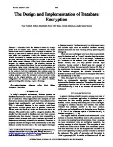
2. BLUETOOTH SECURITY ARCHITECTURE The Bluetooth specifications include security features at the link level [1]. They support authentication (unidirectional or mutual) and encryption (Fig. 1). These features are based on a secret link key that is shared by a pair of devices. Authentication is based on a challenge-response procedure [1], where the verifier issues a random number. This random number is encrypted by the claimant (the other unit) using the shared key and sent back to the
1
Proceedings of IEEE International Symposium on Circuits & Systems (ISCAS'02), Vol. IV, pp. 878-881, USA, May 26-29, 2002 verifier. The verifier checks if the encrypted message is correct. PIN
PIN
E2
E2
diffusion, and second, they use additive constant factors (Bias vectors) in the scheduling for weak keys avoidance. 0
1
2
3
4
5
6
7
8
9
10
11
12
13
14
15
K2r-1 128
e
Authentication
Link Key
E1
l
e
e
l
l
e
e
l
l
e
e
l
l
e
K 2r 128
E3
PHT
E3
Encryption E0
Figure 1: Bluetooth Security Architecture The authentication scheme is performed by using a stream-cipher (Ar), a common key and a Bluetooth address (Fig. 2). RAND
PHT
PHT
PHT
PHT
PHT
PHT
PHT
PHT
PHT
PHT
PHT
PHT
PHT
"Armenian Shuffle" Permutation
Encryption Key
Rounds r, r = 1,2,...,8
Encryption Key
l
Link Key
PHT
PHT
PHT
PHT
PHT
PHT
"Armenian Shuffle" Permutation
PHT
PHT
PHT
PHT
PHT
PHT
"Armenian Shuffle" Permutation
PHT
ADDRESS
PHT
PHT
PHT
PHT
PHT
K 17 K
128
Ar
0
ADD
2
3
4
5
6
7
8
9
10
11
12
13
14
15
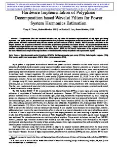
Figure 3: One Round of the SAFER+ Algorithm
XOR
offset
1
Extent
The SAFER+ algorithm consists of a set of eight round and a parallel mechanism for generating the round keys, which are used in each round [1]. The algorithm produces a 128 bits result from a 128 bit “random” input string and a 128 bits round key (Fig. 3). More details about the SAFER+ algorithm are described in [1], [2] and [7].
L
Ar'
SRES / ACO
Figure 2: Bluetooth Authentication Scheme
4. PROPOSED ARCHITECTUR E
The cipher seed generator is a version of the public SAFER+ cipher, which takes a 128 bits key and a 128 bits data block and proceeds the encrypted data [2]. The key exchange procedure is based on a common PIN number, which, entered manually by user on both communication units. It is then used to encrypt a common random number. The SAFER+ algorithm is an enhanced version of an existing 64 bits block cipher SAFER K-128.
The architecture for the hardware implementation of the SAFER+ algorithm consists of the two main components, the data encryption path and the key scheduling. The round keys are applied in parallel in the encryption data path. In addition the data encryption path consis ts of an encryption round structure. For the implementation of the total encryption algorithm the data are applied in a repeated manner to the round structure by using a Feedback Register and an Input Buffer. In this proposed design the whole single round of the SAFER+ algorithm is implemented in hardware. In order to run the whole SAFER+ algorithm eight loops of the single round implementation are needed (Fig. 4). The single round implementation is chosen because the required system throughput can be achieved and in the same time the covered area is minimized.
3. DESCRIPTION OF SAFER+ ALGORITHM The SAFER+ (Secure And Fast Encryption Routine) algorithm is based on the existing SAFER family of ciphers, which comprises the ciphers SAFER K-64, SAFER K-128, SAFER SK-128. They have been developed by James L. Massey at the ETH Zurich [4], [5], [6]. All algorithms are byte-oriented block encryption algorithms, which are characterized by the following two properties. First, they use a non-orthodox linear transformation, which, is called Pseudo-Hadamard-Transformation (PHT) for the desired
2
Proceedings of IEEE International Symposium on Circuits & Systems (ISCAS'02), Vol. IV, pp. 878-881, USA, May 26-29, 2002 Input Key
Control1
Key scheduling
128
implemented by using one look-up table (LUT) with 256 bytes. The Data Demapping unit performs the reverse function of the Data Mapping. This design results in a 25 percent reduction of the covered area comparing to the conventional implementation. After that, the output of the nonlinear layer is added by a mixed byte-addition/XOR with the round key K2r [8]. The operations after that are four Pseudo-Hadamard-Transformation (PHT) layers that are connected through by three permutations. The PHT boxes defined as PHT (in1, in 2) = ( 2in1 + in 2, in1 + in 2) . The outputs of the PHT, out1 = 2in1 + in2 and out2 = in1 + in2 are implemented over in GF(256). The design of PHT element is shown in Fig. 6.
Control Unit
128
Round Keys
Control2
Plaintext
Ciphertext
one SAFER+ encryption round
128 128 128
128
128
Input Register
128
Feedback Register
Figure 4: SAFER+ Block Diagram Hardware Implementation A multiplexer is used in order to feed the one SAFER+ round with the Plaintext in the first round, and for the next seven round with the round encryption internal data. The detailed design of the one SAFER+ encryption round unit with the Input and Feedback registers is shown in Fig. 5.
In1
In2 8
Plaintext 128
SHL 1 Clock Reset
0
1
8
2 8
3 8
4 8
INPUT REGISTER(BUFFER) 6 7 8 9 10 11 12 13 14 15
5
8
8
8
8
8
8
8
8
8
8
8
x
x2
Data_ready Reset_Data_ready
8
8
K2r-1 128
8
8
8
Data Mapping for e , l Functions x1 8 x2 8
e
l
+
y1 8 y2 8 Data Demapping for e , l Functions
+
K2 r 128
PHT
PHT
PHT
PHT
PHT
PHT
PHT
PHT
PHT
PHT
PHT
PHT
PHT
PHT
PHT
PHT
PHT
PHT
"Armenian Shuffle" Permutation
PHT
PHT
PHT
PHT
PHT
PHT
Out1
Round_complete
"Armenian Shuffle" Permutation
PHT
PHT
PHT
PHT
PHT
PHT
0
2
4
6 7 8 9 10 11 12 13 14 15 FEEDBACK REGISTER
Out2
Figure 6: The PHT Implementation Multiplication by 2 can be achieved by one bit left wired shift. The four linear PHT layers connected through the permutations. The permutation boxes show how input byte indices are mapped into the output byte indices. Thus, position 0 (leftmost) is mapped on position 8, position 1 is mapped on position 11, etc.
"Armenian Shuffle" Permutation
PHT
8
8
PHT
only after last round
K1 7
128
1
3
5
Reset_Complet e
128
Key Sel
128
128 bits Key Register
Complete Ciphertext
8
8
Sum bytes bit-by-bit modulo two
Figure 5: The One SAFER+ Encryption Round M U X 2
The output of the Input Register is used as input for the mixed XOR/byte-addition unit with subkey K2r-1 [8]. Symbol denotes bit-by-bit XOR (modulo-2 sum), and symbol denotes additions mod 256 which is implemented over GF(256). Then the set of the 16 8-bit outputs is used by the Data Mapping unit, which produced the X1 and X2 (8-bit words). These words are the input of the non-linear layer units (e and l). The nonlinear function “e” is implemented as y 1 = 45 x 1 in
Select bytes 8
M U X 1
K2r-1 128
8
Bias2r-1
Rotate each octet left by 3 bit positions 8
8
8
8
K 2r Select bytes
+16 128
Bias2r
Rotate each octet left by 3 bit positions 128
GF(257) with the exception 45128 = 0 . The “l” function is implemented as y 2 = log 45 ( x 2 ) in GF(257) with the exception
+16
Select bytes
K 17 +16 128
Bias17
log 45 (0) = 128 . Each non-linear function is
Figure 7: VLSI Implementation of the Key Scheduling
3
Proceedings of IEEE International Symposium on Circuits & Systems (ISCAS'02), Vol. IV, pp. 878-881, USA, May 26-29, 2002 The process of keys generation is characterized by the 128-bit user-selected key, which divided into 16 bytes. The round keys (Key Scheduling) generation is illustrated in Fig. 7. The round keys r, (r=1, 2,…, 8) are denoted as K 2r −1 [ j ], K 2 r [ j], j = 0,1,2...,15 . The user-selected key itself is
Architecture
Rounds
Frequency
Archit. in [3]
8
44 MHz
704 Mb/sec
used as the first round key K 1[ j ] . Finally, the Key Scheduling use 16 16-byte bias vectors, B2, B3,...,B17 which are computed according to the equation [1]:
Archit. in [2] Software1 [3] Software2 [2]
8 8 8
62 MHz 200 MHz 16 MHz
58.9 Mb/sec 33 Mb/sec 25.6 Kb/sec
Proposed
8
20 MHz
320 Mb/sec
17 p +i +1
B[ p, i] = ((45(45
mod257 )
Throughput
Table II: Performance Comparisons
mod 257 ) mod 256) 6. CONCLUSIONS In this paper, a high-speed implementation for the SAFER+ algorithm is proposed. With the aid of iterative looping structure a very high data throughput of 320 Mbit/sec at a clock of 20 Mhz was achieved, with 25 percent covered area reduction. The whole design was captured entirely in VHDL language and implemented in a XILINX VIRTEX XCV400 FPGA device. Measurement results and comparisons between the proposed and previous hardware and software implementations are presented.
for i=0,…15. The B[p,i] correspondence the i-th byte of the bias vector Bp. The bias vectors are implemented by using one 16x16-byte look-up table (LUT). The Key scheduling design allows an on-the-fly computation of the round keys because the Bluetooth demand only the encryption mode of the SAFER+ algorithm. This means that there is no time delay for the key calculation. 5. EXPERIMENTAL AND SIMULATION RESULTS The whole design was captured entirely in VHDL language. All of the system components have been described with structural architecture. The proposed architecture is synthesized by using FPGA device of XILINX [9]. The system was simulated, for the verification of the correct functionality in real time operation conditions. The test vectors provided by [7] for the SAFER+ algorithm were applied to assure that the design was working as intended. Measurements for the proposed SAFER+ implementation resource utilization are presented in Table I. Target Device VIRTEX XCV400 [9] Speed Grade -3 Resource Used Avail Utilization I/Os 392 404 97 % Functions 8335 9600 87 % Generators CLB Slices 4168 4800 87 % Dffs or Latches 810 9600 8.5 %
7.
REFERENCES
[1] “Specification of the Bluetooth System”, Specification Volume 1, Version 1.1, February 22, 2001. [2] J. L. Massey, G. H. Khachatrian, M. K. Kuregian, “SAFER+ Cylink Corporation’s Submission for the Advanced Encryption Standard”, First Advanced Encryption Standard Candidate Conference, Ventura, CA, August 20-22, 1998. [3] J. L. Massey, “On the Optimality of SAFER+ Diffusion”, Second Advanced Encryption Standard Candidate Conference (AES2), Rome, Italy, March 22-23, on line available at http://csrc.nist.gov/encryption/aes/round1/conf2/aes2conf.htm. [4] J. L. Massey, “SAFER K-64: A Byte-Oriented Block Ciphering Algorithm”, Fast Software Encryption, Proceedings of the Cambridge Security Workshop, Cambridge, U.K, 1998, pp. 1-17. [5] J. L. Massey, “SAFER K-64: One Year Later”, Fast Software Encryption, Lectures Notes in Computer Science No. 809, New York, Springer, pp. 212-241, 1994. [6] B. Schneier, “Applied Cryptography, Protocols, Algorithms, and Source Code in C”, John Wiley & Sons 1994. [7] J. L. Massey, G. H. Khachatrian, M. K. Kuregian, “Nomination of SAFER+ as Candidate Algorithm for the Advance Encryption Standard”, First Advanced Encryption Standard Candidate Conference, Ventura, CA, August 20-22, 1998. [8] A. Schubert, V. Meyer, W. Anheier, “Reusable Cryptographic VLSI Core Based on the SAFER K-128 Algorithm with 251,8 Mbits/s Throughput”, IEEE Workshop on Signal Processing Systems, 1998, pp. 437-446. [9] Xilinx, San Jose, California, USA, Virtex, 2.5 V Field Programmable Gate Arrays, 2001, www.xilinx.com
Table I: Resource Utilization Measurements Performance comparisons between the proposed and previous designs are shown in Table II. The software1 implementation was coded in C and executed on 200 MHz Pentium PC [2], [3], and software2 implementation was coded in Assembly on 8-bit Processors of the MCS 51 family [2]. The encryption throughput of the proposed implementation is 5 times higher than the one proposed in [2], and many times higher comparing to the software implementations.
4