Hardware implementation study of the Deficit Table egress link scheduling algorithm R. Mart´ınez
J.M. Claver
F.J. Alfaro, J.L. S´anchez
Intel-UPC Barcelona Research Center Barcelona, SPAIN 08034 Email:
[email protected]
Dpto. de Inform´atica Univ. Valencia Burjassot, SPAIN 46100 Email:
[email protected]
Dpto. de Sistemas Inform´aticos Univ. Castilla-La Mancha Albacete, SPAIN 02071 Email: falfaro,
[email protected]
Abstract—The provision of Quality of Service (QoS) in computing and communication environments has increasingly focused the attention from academia and industry during the last decades. Some of the current interconnection technologies include hardware support that, adequately used, allows to offer QoS guarantees to the applications. The egress link scheduling algorithm is a key part of that support. Apart from providing a good performance in terms of, for example, good end-to-end delay (also called latency) and fair bandwidth allocation, an ideal scheduling algorithm implemented in a high-performance network with QoS support should satisfy other important property which is to have a low computational and implementation complexity. In this paper, we propose a specific implementation of the DTable scheduling algorithm and show estimates about its complexity in terms of silicon area and computation delay. In order to obtain these estimates, we have performed our own hardware implementation using the Handel-C language and employed the DK design suite tool from Celoxica.
I. I NTRODUCTION The availability of high-speed networking has introduced opportunities for new applications. Current packet networks are required to carry not only traffic of applications, such as e-mail or file transfer, which does not require pre-specified service guarantees, but also traffic of other applications that requires different performance guarantees, like real-time video or telecommunications [12]. The best-effort service model, though suitable for the first type of applications, is not so for applications of the other type [14]. Even in the same application, different kinds of traffic (e.g. I/O requests, coherence control messages, synchronization and communication messages, etc.) can be considered, and it would be very interesting that they were treated according to their priority [5]. The provision of QoS in computing and communication environments has been the focus of much discussion and research in industry and academia during the last decades. A sign of this growing interest in industry is the inclusion of mechanisms intended for providing QoS in some of the last network standards like Gigabit Ethernet, InfiniBand (IBA), or Advanced Switching (AS). Note that these technologies are the most common ones for the construction of clusters. An interesting survey with the QoS capabilities of the three standards can be found in [15].
Common characteristics of the specifications of these network technologies intended to provide QoS are the use of a link-level flow control mechanism, which makes the networks lossless, a reduced set of Virtual Channels (VCs), and an egress link scheduler to arbitrate among the traffic transmitted in each VC. These last two mechanisms permit us to aggregate traffic with similar characteristics in the same VC and to provide each VC with a different treatment according to its requirements, at the style of the differentiated services (DiffServ) QoS model [2]. The output (or egress link) scheduling algorithm (also called service discipline) is a key component of this kind of interconnect technologies [6],[21]. A lot of possible scheduling algorithms have been proposed in the literature. However, most of these algorithms were proposed for the Internet scenario with a high number of possible flows, without taking into account a link-level flow control mechanism, and were intended mainly to be implemented by software. These characteristics differ from the requirements of current high-performance networks, which are used for example in clusters. Apart from providing a good performance in terms of, for example, good end-to-end delay (also called latency) and fair bandwidth allocation, an ideal scheduling algorithm implemented in a high-performance network with QoS support should satisfy other important property which is to have a low computational and implementation complexity [17]. We can measure the complexity of a scheduler based on two parameters: Silicon area required to implement the scheduling mechanism and time required to determine the next packet to be transmitted. A short scheduling time is an efficiency requirement that takes more importance in high-performance networks due to their high speed. Moreover, switches of highperformance interconnection technologies are usually implemented in a single chip. Therefore, the silicon area required to implement the switch elements is a key design feature. Note that the scenario that we are addressing here is very different than for example IP routers with QoS support, where these algorithms are usually implemented by software instead of hardware. The fair queuing algorithms are an important kind of scheduling algorithms that allocate bandwidth to the different flows in proportion to a specified set of weights. The perfect
120 100
50
WFQ SCFQ DRR DTable
Jitter VO (µs)
Average latency VO (µs)
140
80 60 40 20 0
40
WFQ SCFQ DRR DTable
30 20 10 0
0.6 0.65 0.7 0.75 0.8 0.85 0.9 0.95 1
0.6 0.65 0.7 0.75 0.8 0.85 0.9 0.95
140 120 100
50
WFQ SCFQ DRR DTable
80 60 40 20 0
40
WFQ SCFQ DRR DTable
30 20 10 0
0.6 0.65 0.7 0.75 0.8 0.85 0.9 0.95 1
0.6 0.65 0.7 0.75 0.8 0.85 0.9 0.95
Global Input Load
120 100
WFQ SCFQ DRR DTable
80 60 40 20 0
1
Global Input Load 50
Jitter CL (µs)
140
1
Global Input Load
Jitter VI (µs)
Average latency VI (µs)
Global Input Load
Average latency CL (µs)
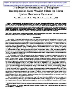
fair queuing scheduling algorithm is the General Processor Sharing (GPS) scheduler [6], [13], which is based on a fluid model that provides perfect instant fairness in bandwidth allocation and has many desirable properties [19], [13]. Different packet-by-packet approximations of GPS have been proposed, which try to emulate the GPS system as accurately and simply as possible while still treating packets as entities. Many scheduling algorithms have been proposed for that. Among them, the “sorted-priority” family of algorithms, like Weighted Fair Queuing (WFQ) [6], Self-Clock Fair Queuing SCFQ [8], and Worst Case Weighted Fair Queuing (WF2Q) [1] are known to offer a good delay [18]. However, their computational complexity is very high, making their implementation in highspeed networks rather difficult. To avoid the complexity of the sorted-priority approach, the Deficit Round Robin (DRR) algorithm [16] has been proposed. The aim of DRR is to implement fair queuing and achieve practically acceptable complexity at the expense of other performance metrics such as fairness and delay. On the other hand, table-based schedulers are intended to provide a good latency performance with a low computational complexity. This approach is followed by two of the last high-performance network interconnection proposals: AS and IBA. In [10] we proposed the Deficit Table (DTable) scheduler. This scheduler on the contrary than the IBA and the AS proposals works in a proper way in networks with variable packet sizes, as is usually the case in current network technologies. Moreover, we proposed a methodology to configure this scheduler in such a way that it permits us to decouple partially the bounding between the bandwidth and latency assignments. Note that in previous fair queuing algorithms the latency provided by the scheduler is directly associated with the amount of bandwidth assigned. In the case of the DTable scheduler, the latency provided to the different VCs depends on the maximum distance between consecutive entries assigned to each VC. In [9] we showed that the latency and the jitter performance provided by the DTable scheduler is near the provided by the much more complex SCFQ and WFQ sorted-priority schedulers and much better than the provided by the DRR scheduler. Some of these results are depicted again in Figure 1, which shows the performance provided by the different schedulers to three types of multimedia traffic that are simultaneously injected into the network with different amounts of best-effort traffic. Taking all this into account we concluded that the DTable scheduler is a good tradeoff among performance and complexity. In this paper, we propose a specific implementation (taking into account the characteristics of current high performance networks) of the DTable scheduling algorithm and show estimates about its complexity in terms of silicon area and computation delay varying some implementation parameters. In order to obtain these estimates, we have performed our own hardware implementation using the Handel-C language [3] and employed the DK design suite tool from Celoxica. The structure of the paper is as follows: Section II presents a summary of the fair queuing scheduling algorithms, focusing
40
WFQ SCFQ DRR DTable
30 20 10 0
0.6 0.65 0.7 0.75 0.8 0.85 0.9 0.95 1
Global Input Load
0.6 0.65 0.7 0.75 0.8 0.85 0.9 0.95
1
Global Input Load
Figure 1. Latency and jitter comparison for controlled load (CL), video (VI), and voice (VO) traffic, for the WFQ, SCFQ, DRR, and DTable schedulers.
on the table-based family of schedulers, including the DTable scheduler. Section III discuss several aspects of the hardware implementation of the DTable scheduler. In Section IV a study of the implementation and computational complexity of the DTable is provided. Finally, some conclusions are given. II. TABLE - BASED FAIR
QUEUING ALGORITHMS
As stated before, the “Sorted-priority” family of algorithms, which includes the WFQ and SCFQ algorithms, is known to offer good delay bounds [18]. This kind of scheduling algorithms assign each packet a tag and the scheduling is made based on the ordering of these tags. However, this family of algorithms suffers from two major problems. The first problem is that these algorithms require processing at line speeds for tag calculation and tag sorting. In other words, each time a packet arrives at a node, its time tag is calculated and the packet is inserted at the appropriate position in the ordered list of packets waiting for transmission. Moreover, a common problem in the sorted-priority approach is that tags cannot be reinitialized to zero until the system is completely empty and all the sessions are idle. The reason is that these tags depend on a common-reference virtual clock and are an increasing function of the time. In other words, it is impossible to reinitialize the virtual clock during the busy period, which, although statistically finite (if the traffic is constrained), can be extremely long, especially given that most communication traffic exhibits self-similar patterns which lead to heavily tailed buffer occupancy distributions. Therefore, for a practical implementation of sorted-priority algorithms, very high-speed hardware is required to perform the sorting, and floating-point units must be involved in the computation of the time tags.
The Deficit Round Robin (DRR) algorithm [16] is a variation of the Weighted Round Robin (WRR) algorithm that works on a proper way with variable packet sizes. In order to handle properly variable packet sizes, the DRR algorithm associates each queue with a quantum and a deficit counter. The quantum assigned to a flow is proportional to the bandwidth assigned to that flow. The sum of all the quantums is called the frame length. For each flow, the scheduler transmits as many packets as the quantum allows. When a packet is transmitted, the quantum is reduced by the packet size. The unused quantum is saved in the deficit counter, representing the amount of quantum that the scheduler owes the flow. At the next round, the scheduler will add the previously saved quantum to the current quantum. When the queue has no packets to transmit, the quantum is discarded, since the flow has wasted its opportunity to transmit packets. The main advantage of the DRR scheduler is its computational simplicity. Due to this, recent research in the Differentiated Services area proposes the DRR as a feasible solution for implementing the Expedited Forwarding Per-hop Behavior [7]. However, the main problem of this algorithm is that its delay depends on the frame length. Depending on the situation, the frame can be very long, and thus, the latency could be very bad. Two recent network technology standards, AS and IBA, incorporate table-based schedulers, which are intended to provide a good latency performance with a small computational complexity. In order to provide a good latency performance, the table-based schedulers distribute the service throughout the entire frame, instead of serving packets of a flow in a single visit per frame. AS and IBA use Virtual Channels (VCs) to aggregate flows with similar characteristics and the arbitration is made at a VC level. In both cases, the maximum number of unicast VCs that a port can implement is 16. The AS tablebased scheduler employs an arbitration table that consists in a register array with fixed-size entries of 8 bits. Each entry contains a field of 5 bits with a VC identifier value and a reserved field of 3 bits. When arbitration is needed, the table is cycled through sequentially and a packet is transmitted from the VC indicated in the current table entry regardless of the packet size. If the current entry points to an empty VC, that entry is skipped. The number of entries may be 32, 64, 128, 256, 512, or 1024. InfiniBand defines a scheduler that uses two tables, one for scheduling packets from high-priority VCs and another one for low-priority VCs. The maximum amount of data that can be transmitted from high-priority VCs before transmitting a packet from the low-priority VCs can be configured. Each table has up to 64 entries. Each entry contains a VC identifier and a weight, which is the number of units of 64 bytes to be transmitted from that VC. This weight must be in the range of 0 to 255, and is always rounded up as a whole packet. On the other hand, Chaskar and Madhow [4] propose a category of scheduler called list-based Weighted Round Robin for being used in networks with fixed packet sizes. Chaskar and Madhow propose three of these list-based WRR
schedulers. All of these schedulers can actually be implemented with the AS table-based scheduler. In all the cases the proportion of table entries associated with each flow indicates the bandwidth assigned to each flow. Therefore, the difference among the three schedulers is in the way of distributing the flow identifiers among the table entries. These different forms of interleaving the flow identifiers result in different latency characteristics for the three schedulers. In their tests, the variant that provides the best latency performance tries to emulate the behavior of the WF2Q algorithm. In [10] we showed that both the AS and IBA table-based schedulers do not work properly with variable packet sizes and proposed a new table-based scheduling algorithm that solves this problem. We have called this algorithm Deficit Table scheduler, or just DTable scheduler, since it is a mix between the previously proposed table-based schedulers and the DRR algorithm. Our scheduler works in a similar way than the DRR algorithm but instead of serving packets of a flow in a single visit per frame, the quantum associated to each flow is distributed throughout the entire frame. Note that we have also considered the possibility of a link-level flow control mechanism when defining this scheduler. This new table-based scheduler defines an arbitration table in which each table entry has associated a flow identifier and an entry weight, which is usually expressed in flow control credits in networks with a credit-based link-level flow control (like AS and IBA). Moreover, each flow has assigned a deficit counter that is set to 0 at the beginning. When scheduling is needed, the table is cycled through sequentially until an entry assigned to an active flow is found. A flow is considered active when it stores at least one packet and the flow control allows that flow to transmit packets. When a table entry is selected, the accumulated weight is computed. The accumulated weight is equal to the sum of the deficit counter for the selected flow and the current entry weight. The scheduler transmits as many packets from the active flow as the accumulated weight allows. When a packet is transmitted, the accumulated weight is reduced by the packet size. The next active table entry is selected if the flow becomes inactive or the accumulated weight becomes smaller than the size of the packet at the head of the queue. In the first case, the remaining accumulated weight is discarded and the deficit counter is set to zero. In the second case, the unused accumulated weight is saved in the deficit counter, representing the weight that the scheduler owes the queue. This behavior, which already considers VCs instead of flows, is represented in the pseudocode shown in Figure 2. Note that, when using the scheduling algorithm with an arbitration table of N entries, the bandwidth assigned to the ith flow φi is: X weightj φi =
j∈I N −1 X e=0
weighte
while (There is at least one active VC) if ((selectedV C is not active) or (selectedV CsizeF irst > accumulatedW eight)) selectedV Cdef icitCounter ← accumulatedW eight tableEntry ← Next table entry assigned to an active VC selectedV C ← tableEntryV CIdentif ier accumulatedW eight ← selectedV Cdef icitCounter + tableEntryweight accumulatedW eight = accumulatedW eight − selectedV CsizeF irst Transmit packet from selectedV C if ((There are no packets in the queue of selectedV C) or (The flow control does not allow transmitting from selectedV C)) accumulatedW eight ← 0 Figure 2.
Pseudocode of the DTable scheduler.
where I is the set of table entries assigned to the ith flow and weight is the entry weight assigned to a table entry. In order to keep the computational complexity low, we set the minimum value that a table entry can have associated to the MTU of the network. This is the smallest value that ensures that there will never be necessary to cycle through the entire table several times in order to gather enough weight for the transmission of a single packet. This means that each time an entry from an active flow is selected, at least one packet is going to be transmitted from that flow. Note that this consideration is also made in the DRR algorithm definition [16]. Note also that in the IBA table-based scheduler this issue is solved by rounding up to a whole packet the remaining weight in a table entry. III. I MPLEMENTING THE D EFICIT TABLE
SCHEDULER
In this section, we discuss several aspects of the hardware implementation of the DTable scheduler. Specifically, we propose several ways of implementing the weight that is assigned to each table entry and show how to convert the AS and IBA table-based schedulers into DTable schedulers. Finally, we address the actual implementation of the next entry search mechanism. A. Possibilities for implementing the entry weights In a general implementation of the DTable scheduler, each entry would consist of a number of bits to store a VC identifier and a big enough number of bits to store an entry weight that allow a flexible assignation of weights of the configuration methodology. However, in order to reduce the memory required by the DTable scheduler, other implementations are possible. 1) Using a fixed weight per entry: The simplest way of implementing the DTable scheduler would be to assign all the table entries the same fixed weight: tableEntry.weight ← W eight In this way, each table entry would only require to specify the VC identifier. However, this approach limits a lot the configuration possibilities of the DTable scheduler. Note that,
in this case, the number of entries assigned to each VC totally determines the bandwidth distribution. 2) Using a limited amount of bits: This possibility consists in employing a reduced number of bits. With this approach the number of possible weights is going to be very limited and thus, several considerations must be made. First of all, as stated before, the entry weight must represent at least the value of the MTU. Therefore, a weight of 0 is not going to be used, and thus, we propose to consider the weight 0 as 1, the weight 1 as 2, etc. This allows us to specify a weight between 1 and 8 with for example a 3-bit field. Moreover, if the number of bits is not enough to represent a value of at least the MTU, each weight unit will represent a weight m equivalent to a certain number of flow control credits. Therefore, when an entry is selected its weight must be translated into its value in flow control credits: tableEntry.weight ← (tableEntry.value + 1) × m Note that this approach limits in a high degree the variability in the weights assignation and thus, the granularity of the bandwidth distribution. 3) Using only one weight per VC: The third possibility that we propose is to associate the same weight to all the entries assigned to a VC. Therefore, we only need to specify a table weight per VC instead of per table entry. This requires, however, an additional structure to configure a weight per VC. When a new table entry is selected, the accumulated weight is computed as: tableEntry.weight ← weightselectedV C B. Converting the AS and IBA table schedulers to a DTable scheduler As stated before, AS and IBA employ table-based schedulers in the egress links to provide QoS. In this section, we show how to implement the DTable scheduler in these technologies modifying as little as possible their specifications. 1) InfiniBand: Each table entry of the IBA scheduling mechanism specifies a VC identifier and a weight. Therefore, the difference between the IBA table and the DTable arises when the size of the packet at the head of the selected VC is
bigger than the remaining amount of information to transmit from that VC. In the InfiniBand case, the packet is transmitted exhausting the remaining weight, but in the DTable case, other table entry is selected, and the remaining weight is stored for future use in the VC deficit counter. Therefore, in order to implement the DTable scheduler in IBA, it is only necessary to add the deficit mechanism. This means to add a deficit counter to each VC and the logic to store and load the remaining weight. Note that these counters are set to zero at the beginning and are modified dynamically by the scheduler itself during the scheduling process, and thus they do not require any user configuration. 2) Advanced Switching: As stated in Section II, the AS arbitration table consists in a list of VC identifiers without any weight assigned to each entry as it is the case in the DTable scheduler. Specifically, each entry contains a field of 5 bits with a VC identifier value and a reserved field of 3 bits. Therefore, apart from adding the hardware to manage a deficit counter per VC, we must indicate in some way the weight assigned to each table entry. As stated before, we have several possibilities: To employ the same weight for all the entries, to use the 3-bit reserved field of each table entry to assign a weight to each entry (this would have the drawbacks stated before), or to modify the structure of the arbitration table in order to dedicate a higher number of bits to the entry weight. In particular, we propose to use two bytes per table entry, and use 5 bits for the VC identifier and up to 11 for the entry weight. This number of bits is high enough to directly employ it for storing the entry weight. These possibilities and the benefits and drawbacks of each one are discussed in more detail in [11]. C. Hardware implementation of the DTable scheduler When a new packet is notified to the DTable scheduler, it just takes note of the packet size and actives the VC if there are enough flow control credits to transmit that packet. Once one VC has been selected to transmit, the scheduler transmits from the same VC until the VC becomes inactive or the remaining entry weight is not enough to transmit the packet at the head of the VC queue. In order to select a new VC to transmit from, the arbitration table must be looked over sequentially searching for the next active entry and skipping those entries that refer to a VC without packets or credits to transmit. Although the checking of each entry can be made with very simple computational units, in the worst case all the table must be looked over in order to find the next active entry. In order to make the process faster, several entries of the table can be read simultaneously at the expense of increasing the silicon area and probably the cycle time. This algorithm also requires the memory necessary to store the arbitration table. A possible way to read several entries simultaneously in an efficient way is to split the register array or memory block in several subblocks and read one entry of each of these subblocks in the same cycle. We have called the number of simultaneous table entries that are read in a single cycle the parallelization grade. Figure 3 shows the structure of the
Figure 3.
Structure of the selector module for the parallel table scheduler.
mechanism that we have implemented to obtain the next active table entry. First of all we read from the last selected table entry a certain number of consecutive table entries equal to the parallelization grade. The next cycle, we check if any of those entries refers to an active VC. At the same time, the next ‘parallelization grade’ entries are read. When the mechanism realizes that at least one entry is active in the set of table entries, the process stops and a bitonic network is employed to calculate which is the first active entry in the subblock. Table I shows the number of cycles required to make the arbitration decision in both cases, when the table is cycle through sequentially or, when various entries are processed at the same time. Note that the number of cycles required to complete the arbitration is variable and depends on how far from the last selected entry is the next selected entry. When the load of the network is low, more cycles will be probably required in average to find the next table entry. When the load of the network is high, most VCs will be active anytime, and thus the average number of cycles will be very small. Note also that the arbitration time includes the entry search but also other aditional operations that are already reflected in Table I. IV. H ARDWARE
ESTIMATES
In this section we analyze our proposal for an implementation of the DTable scheduler in terms of its implementation and computational complexity. We have modeled this scheduler using Handel-C language [3] and employed the DK design suite tool from Celoxica in order to obtain hardware estimates on silicon area and arbitration time. Handel-C’s level of design abstraction is above Register Transfer Level (RTL) languages, like VHDL and Verilog, but below behavioral. In Handel-C each assignment infers a register and takes one clock cycle to complete, so it is not a behavioral language in terms of timing. The source code completely describes the execution sequence and the most complex expression determines the clock period. Note that the Handel-C code that we have designed can actually be used to implement the DTable scheduler in a Field Programmable Gate Array (FPGA) or, if the appropriate
Table I A RBITRATION TIME IN CYCLES FOR SEQUENTIAL AND PARALLEL IMPLEMENTATIONS OF THE DTABLE SCHEDULER .
Search Sequential Parallel
Number of cycles [3 .. #Entries + 2] #Entries [log2 (P arallel Grade) + 4 .. + log2 (P arallel Grade) + 3] P arallel Grade
conversion is made, in an Application Specific Integrated Circuit (ASIC). However, this has not been the objective of our work, but to obtain the relative differences on silicon area and arbitration time required by our implementation of the DTable scheduler under different implementation parameters. In order to obtain the hardware estimates in which we are interested: 1) We have modeled in Handel-C a full egress queuing system, including the scheduler. 2) We have validated the scheduler employing the simulation and debugging functionality of the DK design suite. 3) We have isolated the scheduler module in order to obtain estimates without influence of other modules. 4) We have obtained the Electronic Design Interchange Format (EDIF) output for a Virtex 4 FPGA from Xilinx. A cycle count is available from the Handel-C source code: Each statement in the Handel-C source code is executed in a single cycle in the resulting hardware design and thus, the number of cycles required to perform a given function can be deduced directly from the source code. Moreover, an estimate of gate count and cycle time is generated by the EDIF Handel-C compiler. The cycle time estimate is totally dependent on the specific target FPGA, in this case the Virtex 4 [20], which is one of the last FPGA models provided by Xilinx. However, as our objective is to obtain relative values instead of absolute ones, we consider that this approach is good enough to be able to compare the complexity in terms of silicon area and scheduling time of the different configurations. Figure 4 reflects the design flow that we have followed.
Figure 4.
Design flow with the DK employing Handel-C.
In order to obtain hardware estimates of the DTable scheduler we have considered the number of VCs, the number of table entries, and the parallelization grade as design parameters. Moreover, we have also calculated hardware estimates to compare the original AS table with the possible implementations of the DTable scheduler shown in Section III-A. Figure 5 shows the difference in silicon area and arbitration time for different possibilities to implement the entry weight. Specifically, it compares a table without the deficit mechanism, like the original AS table based scheduler (Original), a table that employs the same weight for all the table entries (FixedW), a table that assigns the same weight for all the entries assigned to a VC (W-VC), a table that employs 3 bits for specifying the entry weight (3-bits), and a table that employs two bytes to codify both the VC identifier and the table entry weight (2-bytes). The figure shows the increment in silicon area and time with respect to the original AS table scheduler. Note that the increment in time refers to both, the minimum and maximum arbitration time required by the scheduler. In that figure we can see that employing a fixed weight for all the table entries only requires 10% more silicon area than the original AS table scheduler. In the case of the AS table scheduler this would solve the problem of the original scheduler with variable packet size, although the decoupling methodology could not be used. In the case of IBA, that 10% increment in area would represent the deficit mechanism, and as each IBA table entry already specifies a weight, the result would be a full DTable scheduler. This figure also shows that the 2-byte option is the most demanding one. This option requires 80% more silicon area than the original AS table compared with the 35% of the 3-bit option. Moreover, the arbitration time is slightly higher (0.85%) than in the rest of the cases, which have the same arbitration time, and thus the increment is 0%. In the rest of this work we will show statistics of the 2-byte DTable option because is the worst case for all the table implementations. Moreover, this is the possibility that provides the best flexibility and granularity to the decoupling methodology. Figure 6 shows the effect of the number of VCs over the complexity of the DTable. Specifically, it shows the increment in silicon area and arbitration time required with respect to the 2-VC case. This figure shows that this parameter affects in a high degree the silicon area required and, when the number of VCs is very high, a little the arbitration time. Note that in these figures the X axis is in logarithmic scale, thus a linear growth in data plot actually means a logarithmic data growth, and an
40 20
600 500
0.6 0.4 0.2
0 W−VC
3−bits
400 300 200
0
2−bytes
Original FixedW
Table implementation
W−VC
3−bits
1
4
8
Arbitration time incr. (%)
50
0
15
16
5
2
4
8
16
Cycle time incr. (%)
Area increment (%)
500 400 300 200 100 0 512
4000 3000 2000 1000 0 Table entries
8
16
32
Minimum Maximum
400 300 200 100
64
1
4
8
16
32
64
Parallelization grade
1024
1200
2 VCs 4 VCs 8 VCs 16 VCs 32 VCs
6000 4000
1000 800
2 VCs 4 VCs 8 VCs 16 VCs 32 VCs
600 400 200 0
32
64
128
256
512
1024
32
64
Table entries
300
4000
200
64
128
256
512
1024
1000
Minimum Maximum
800 600
3500 3000 2500
2 VCs 4 VCs 8 VCs 16 VCs 32 VCs
2000 1500 1000 500 64
128
256
Table entries
200
32
64
128
256
512
1024
256
512
1024
3500 3000 2500
512
1024
2 VCs 4 VCs 8 VCs 16 VCs 32 VCs
2000 1500 1000 500 0
32 400
128
Table entries 4000
0
0 512
8000
400
32
Arbitration time incr. zoom (%)
Arbitration time incr. (%)
5000
256
4
0
Table entries
6000
128
64
0
10000
500
1024
Minimum Maximum
64
500
12000
600
0
32
1000
2000
Table entries
7000
1500
Cycle time incr. (%)
700
100
8000
32
32
800
256
16
VCs
600
128
8
Parallelization grade
Figure 8. Effect of the parallelization grade over the DTable silicon area and arbitration time (8 VCs and 128 entries).
32
Figure 6. Effect of the number of VCs over the DTable silicon area and arbitration time (128 entries and a parallelization grade of 16).
64
4
500
Parallelization grade
VCs
32
1
Max. Arbitration time incr. (%)
8
64
Minimum Maximum
1
Area increment (%)
4
32
2000
10
0 2
16
0
Min. Arbitration time incr. (%)
Area increment (%)
20
Arbitration time incr. (%)
2500
100
5
Parallelization grade
Figure 5. Complexity comparison of the different possible DTable implementations (8 VCs, 128 entries, and a parallelization grade of 16).
150
10
0
2−bytes
Table implementation
200
15
100
0 Original FixedW
20 Cycle time incr. (%)
60
1 0.8
Arbitration time incr. zoom (%)
80
Area increment (%)
Arbitration time incr. (%)
Area increment (%)
100
512
1024
32
64
128
256
Table entries
Figure 9. Silicon area and arbitration time increment for the combined effect of the number of table entries and of VCs (parallelization grade of 16).
Table entries
Figure 7. Effect of the number of table entries over the DTable silicon area and arbitration time (8 VCs and a parallelization grade of 16).
exponential growth actually means a linear data growth. Figure 7 shows the effect of the number of table entries over the complexity of the DTable. Specifically, this figure shows the increment in silicon area, cycle time, and minimum and maximum time required to perform the arbitration with respect to the silicon area and minimum time required in the 32-entry case. This parameter affects in a high degree both the silicon area and the arbitration time. The increment in the silicon area is due to the increment in the space required to store the arbitration table and the extra logic to handle it. Note that if we were considering some of the other possibilities to codify the entry weight, and not the 2-byte option like is the case, the increment would be lower. Regarding the arbitration time, its increment is due to the increment in the cycle time, but also to the extra number of cycles required to process a bigger table. In particular, the increment in the cycle time
determines the increment in the minimum time required to make the arbitration. Note that we use the same parallelization grade in all the cases and thus, the same minimum number of cycles is required to perform the arbitration. On the other hand, the maximum number of required cycles increases with the table size and thus, the maximum required time increases due to both, the cycle time and the number of cycles increment. A way to reduce the arbitration time is to increase the parallelization grade. Figure 8 shows the effect of this parameter over the DTable scheduler. Specifically, this figure shows the increment in silicon area, cycle time, and minimum and maximum time required to perform the arbitration, with respect to the silicon area and minimum time required when the parallelization grade is 1 (sequential search). This figure shows that increasing the parallelization grade also increases in a high degree the silicon area required. This extra area is not so exacerbate when we increase only a bit the parallelization grade. However, if we increase the value of this parameter a lot, the silicon area increases much faster. Figure 8 also
shows that given a certain number of entries (128 in this case), the effect of increasing the parallelization grade is to reduce the maximum number of cycles required to perform the arbitration at the cost of increasing the minimum number of cycles. However, this figure shows that increasing too much the parallelization grade affects in a negative way both the minimum and maximum arbitration time because of the increment in the cycle time. Until now we have shown the individual effects of varying the value of the different design parameters over a basic configuration of a 2-byte DTable with 128 entries, a parallelization grade of 16, and 8 VCs. Figure 9 shows a more general picture in which we observe the effect of varying the number of VCs for every table size. At the same time we vary the parallelization grade in order to keep constant and equal to 16 the number of cycles required to process all the table entries (number of entries / parallelization grade = 16). Note that even with this last consideration, the number of cycles is not the same in each combination of number of entries and parallelization grade (see Table II). The increments shown are with respect to a DTable with 32 entries and 2 VCs. Table II C OMBINATION OF VALUES FOR THE NUMBER OF TABLE ENTRIES , THE PARALLELIZATION GRADE , AND THE ARBITRATION TIME IN CYCLES .
Number of table entries 32 64 128 256 512 1024
Parallelization grade 4 8 16 32 64 128
Arbitration time (cycles) 6 - 13 7 - 14 8 - 15 9 - 16 10 - 17 11 - 18
Figure 9 shows that when the number of table entries grows, the silicon area required increases dramatically due to the accumulated effect of the increment on the table size and the parallelization grade. A smaller arbitration time could be achieved increasing more the parallelization grade. However, this would increase even more the silicon area required. Figure 9 also shows that the number of VCs is only relevant for the arbitration time for small arbitration table sizes. If the number of entries in the arbitration table is high, then the cycle time, and consequently the arbitration time, are independent of the number of VCs. V. C ONCLUSIONS
AND FUTURE WORK
In this paper, we propose a specific implementation of the DTable scheduling algorithm. Specifically, we propose to employ a parallel traversal of the table entries in order to reduce the maximum number of cycles required to perform the scheduling. We have also proposed several possibilities to decrease the area requirements of the table employed by the scheduler. Moreover, we have obtained estimates about DTable scheduler complexity in terms of silicon area and computation time varying some implementation parameters. In order to
obtain these estimates, we have performed our own hardware implementation using the Handel-C language. The hardware estimates show that with only 10% increment in area the InfiniBand table scheduler would be converted in a full DTable scheduler. In the case of the AS table scheduler, that 10% increment would solve this scheduler problem with variable packet sizes, and with 80% increment (for a table with 128 entries and 16 VCs) we would have a full implementation. The hardware estimates also show the importance of the number of entries and the parallelization grade, which is the number of table entries that we read each cycle in our parallel implementation, over the area and arbitration time of the scheduler. The number of VCs is also an important parameter but in a lower degree. R EFERENCES [1] J. Bennett and H. Zhang. WF2Q: Worst-case fair weighted fair queueing. INFOCOM, 1996. [2] S. Blake, D. Back, M. Carlson, E. Davies, Z. Wang, and W. Weiss. An Architecture for Differentiated Services. Internet Request for Comment RFC 2475, Internet Engineering Task Force, December 1998. [3] Celoxica. Handel-C Language Reference Manual for DK4, 2005. [4] H. M. Chaskar and U. Madhow. Fair scheduling with tunable latency: A round-robin approach. IEEE/ACM Transactions on Networking, 11(4):592–601, 2003. [5] L. Cheng, N. Muralimanohar, K. Ramani, R. Balasubramonian, and J. B. Carter. Interconnect-aware coherence protocols for chip multiprocessors. In ISCA, pages 339–351. IEEE Computer Society, 2006. [6] A. Demers, S. Keshav, and S. Shenker. Analysis and simulations of a fair queuing algorithm. In SIGCOMM, 1989. [7] A. Charny et al. Supplemental information for the new definition of EF PHB (Expedited Forwarding Per-Hop-Behavior). RFC 3247, March 2002. [8] S. J. Golestani. A self-clocked fair queueing scheme for broadband applications. In INFOCOM, 1994. [9] R. Mart´ınez, F. J. Alfaro, and J. L. S´anchez. A framework to provide quality of service over Advanced Switching. IEEE Transactions on Parallel and Distributed Systems, 19(8):1111–1123, 2008. [10] R. Mart´ınez, F. J. Alfaro, and J.L. S´anchez. Decoupling the bandwidth and latency bounding for table-based schedulers. International Conference on Parallel Processing (ICPP), August 2006. [11] R. Mart´ınez, F. J. Alfaro, and J.L. S´anchez. Studying several proposals for the adaptation of the DTable scheduler to Advanced Switching. International Symposium on Parallel and Distributed Processing and Applications (ISPA), December 2006. [12] P. L. Montessoro and D. Pierattoni. Advanced research issues for tomorrow’s multimedia networks. In International Symposium on Information Technology (ITCC), 2001. [13] A. K. Parekh and R. G. Gallager. A generalized processor sharing approach to flow control in integrated services networks: The singlenode case. IEEE/ACM Transactions on Networking, 1993. [14] K. I Park. QoS in Packet Networks. Springer, 2005. [15] S.A. Reinemo, T. Skeie, T. Sødring, O. Lysne, and O. Trudbakken. An overview of QoS capabilities in InfiniBand, Advanced Switching Interconnect, and Ethernet. IEEE Communications Magazine, 44(7):32– 38, 2006. [16] M. Shreedhar and G. Varghese. Efficient fair queueing using deficit round robin. In SIGCOMM, pages 231–242, 1995. [17] V. Sivaraman. End-to-Ent delay service in high speed packet networks using Erliest Deadline First Scheduling. PhD thesis, University of California, 2000. [18] D. Stiliadis and A. Varma. Latency-rate servers: A general model for analysis of traffic scheduling algorithms. IEEE/ACM Transactions on Networking, 1998. [19] J. S. Turner. New directions in communications (or which way to the information age). IEEE Communications, 24(10):8–15, October 1986. [20] Xilinx. Virtex-4 family overview. Fact sheet DS112 (v2.0), June 2007. [21] H. Zhang. Service disciplines for guaranteed performance service in packet-switching networks, 1995.