Indian Journal of Geo-Marine Sciences Vol. 41(6), December 2012, pp. 575-580
Hardware-In-the-loop simulation platform for the design, testing and validation of autonomous control system for unmanned underwater vehicle Vishnu Kumar Kaliappan1+, Agus Budiyono2*, Dugki Min1#, Muljowidodo K3, SaptoAdiNugroho3 1
School of computer Science and Engineering, Konkuk University, Seoul, Korea. 2
Department of Aerospace Engineering, Konkuk University, Seoul, Korea.
3
Center for Unmanned System Studies (CentrUMS), InstitutTeknologi Bandung, Bandung, Indonesia [E-mail: #
[email protected],
[email protected], *
[email protected]] Received 26 July 2012; revised 17 August 2012
Significant advances in various relevant science and engineering disciplines have propelled the development of more advanced, yet reliable and practical underwater vehicles. A great array of vehicle types and applications has been produced along with a wide range of innovative approaches for enhancing the performance of unmanned underwater vehicle (UUV). These recent advances enable the extension of UUVs’ flight envelope comparable to that of manned vehicles. For undertaking longer missions, therefore more advanced control and navigation will be required to maintain an accurate position over larger operational envelope particularly when a close proximity to obstacles (such as manned vehicles, pipelines, underwater structures) is involved. In this case, a sufficiently good model is prerequisite of control system design. System evaluation and testing of unmanned underwater vehicles in certain environment can be tedious, time consuming and expensive. This paper, focused on developing dynamic model of UUV for the purpose of guidance and control. Along with this a HILS (Hardware-In-the-Loop Simulation) based novel framework for rapid construction of testing scenarios with embedded systems has been investigated. The modeling approach is implemented for the AUV Squid, an autonomous underwater vehicle that was designed, developed and tested by research team at Center for Unmanned System Studies at InstitutTeknologi Bandung. Keywords: Robotics Fault tolerant controller, unmanned aerial vehicle, reconfigurable controller, fault detection, Hardware in the Loop.
Introduction Unmanned vehicles are widely used in military and civilian segments. These systems include unmanned aerial vehicle (UAV), unmanned ground vehicle (UGV), and unmanned underground vehicle (UUV)1. Most of the system are only semi autonomous, and rely on human interventions. To make such system to be fully autonomous, an fully flexible and reliable autonomous control system should be developed. Especially very few research work is undertaken in development of UUV control system. UUV shares a common control problem like UUV and UGV except few limitations in an underwater environment. Developing the control system for UUV presents several challenges due to number of factors such as inherent nonlinearity of the underwater vehicle dynamics, calculation of hydrodynamic coefficients, limited operational underwater sensors, etc. Few —————— *Author for correspondence
control techniques has been investigated for UUV in both simulation and actual water experiments. Among them few approach of control algorithm are behaviorbased2, reference model3,4, artificial intelligent based approach5, etc. This paper focus on the development of modelbased control design and navigation system design and a novel testing framework was developed to validate the system. The system uses Hardware-inthe-loop-simulation environment where the UUV is visualized in virtual space. Based on the real control data the virtual UUV forms the underwater trajectory. Unmanned Underwater Vehicle (UUV) model The equations of motion of UUV contain three elements: vehicle kinematics, rigid body dynamics and vehicle mechanics. The center of gravity is taken as the origin for body coordinate system used for deriving the equations of motion. More complete derivation can be found in6.
576
INDIAN J. MAR.SCI., VOL. 41, NO. 6, DECEMBER 2012
Kinematics of UUV
Two coordinate systems are used in describing the motion of UUV: Earth inertial system (fixed frame) and body coordinate (moving frame). The relation between Euler angular rates and angular velocities with respect to body frame is given by:
… (7) … (8) Gravity and Buoyancy Forces and Moments
… (1) or
The first components of forces and moments come from gravity and buoyancy representing hydrostatic forces. Expressed in the body frame, the hydrostatic forces and moments can be written as: … (9)
... (2) Dynamics of UUV as a Rigid Body
The description of forces equation for a vehicle moving in inertial frame of reference is given by Euler-Newton equation: … (10) … (3) Assuming the vehicle mass is constant and the forces are evaluated with respect to body frame which moves with respect to the inertial frame of reference, the expression can be rewritten as: ... (4) the forces equation can be decomposed into three scalar components:
Added Mass Forces and Moments
The second components are from added mass which is the hydrodynamic force due to the acceleration of the vehicle. For a general body, the added mass is given in terms of tensor with elements of Aij representing the magnitude of the added mass in the –i direction due to acceleration in the –j direction. The values of i,j from 1 to 3 represents the masses associated with surge, sway and heave motions while those from 4 to 6 the moment of inertias associated with roll, pitch and yaw motions. In terms of the equivalent derivative coefficients:
… (5) By the same token, the moments equation read
… (11) Steady-state Forces and Moments
… (6) Dynamics Modeling of UUV
At this stage, to express the external forces and moments that works on a UUV. In general, they can be written in terms of the following contributions:
The steady-state forces and moments are the result of viscous fluid effect and are usually calculated based on semi-empirical/empirical formula or model testing. Multivariate Taylor series expansion around equilibrium point is used to describe the forces and moments. In this approach, it is assumed that the force and moment are function of velocity only: =
KALIAPPAN et al: HARDWARE-IN-THE-LOOP SIMULATION PLATFORM
… (12)
Where
577
Note that for pitch-up or pitch-down maneuver, all three thrusters can also be used simultaneously. Following the description of control for AUV Squid as given in Table 1, each thrust can be expressed as: … (18)
and
In this case, the propulsion force can be given as:
… (13) In practice third order expansion is considered enough. The total number of terms for total forces and moments will be 498. This number can be reduced considerably due to geometric symmetry in two planes and cruciform fin configuration. Propulsion Forces and Moments
The AUV Squid has propeller-based thrusters. For this type of propulsion, the thrust is function of velocity and the number of blade n.
… (19) The control force and moment can therefore be written as:
… (20) or
… (21) … (14) where KT is thrust coefficient, J = advance ratio, ρ= fluid density, and D = propeller diameter. The thrust coefficient can be expressed in terms of cubic of advance ration. … (15) Coefficient of the advance ratio is function of number of blades, pitch-diameter ratio and blade area. The thrust can then be calculated as:
… (16)
Equations of Motion in Longitudinal Mode
Using the expression for the forces and moments contribution from gravity, buoyancy, added-mass, propulsion and control, the equations of motion of the AUV Squid can be formulated Fig. 1. For longitudinal case the expression of forces and moments working on AUV Squid is summarized in Table 2. The control term contains three differential thrusters: δT1, δT2 and δT3. Table 1—Use of thruster in the longitudinal mode Thruster
Maneuver
Control Input
T1
pitch up pitch down
reduction of thrust, δ T1 increase of thrust, +δ T1
T1,T1
pitch up pitch down
increase of thrust, +δ T2,3 reduction of thrust, δ T2,3
and … (17)
Where UA = µ - µw Control Forces and Moments
The control of AUV Squid is provided by differential thrust from three different thrusters. The use of thruster for the control in the longitudinal mode is described in Table 1. For longitudinal mode maneuver, thrusters 2 and 3 can be used simultaneously for the same differential thrust.
Fig. 1—CDM block diagram.
INDIAN J. MAR.SCI., VOL. 41, NO. 6, DECEMBER 2012
578
Table 2—Linear model for longitudinal dynamics of UUV Inertial
Hydrostatics
Added Mass
Steady States
Propulsions
Controls Kinematics
Experimental Test-bed for UUV HILS (Hardware-in-the-loop-simulation)
In the cases like real time testing, most effective method to build an embedded system is to bond embedded system to real dynamics. Most of the system cannot be validated in real time due to the cost effectiveness, complexities in the environments like underwater to compensate; the HIL (Hardware-in-theloop) simulation is used. In this section the complete development of HILS is discussed. The architecture for HILS is exemplified in Figure 2. Vehicle Control Computer (VCC)
It consists of standard PC 104 board (Celeron®M 1GHZ, 256MB DDR DRAM, 64MB Compactable Flash card) running under QNX neutrino6 real time operating system (RTOS). Interface to the embedded processor include Ethernet, USB, RS232 and RS422/485 serial ports. Sensor board consist 6 different I/O modules including PWM, AD, DA, CAN, counter and DIO. It also has PCMCIA for WLAN. The I/O is capable of driving standard servos. The embedded processor communicates with virtual space and plant model with serial ports via HIL bridge. The Ethernet is used to transfer the binaries from the host PC. QNX IDE is capable of uploading the latest vehicle executives to the target embedded board. Figure 4 picture depicts PC104 based onboard computer.
Surface control Station (SCS)
Surface control station (SCS) enables operators to pass commands and monitor the status of the vehicle while in underwater. The software is written in C++ run under windows platform. It is capable of transmit and receive data via Wibro. For test purpose we used serial communication between VCC and SCS. The operator can select different vehicle modes which include manual, semi-auto, fixed-point, automatic, and waypoint. Using waypoint mode the operator can directly assigns the coordinates using the graph. Once the operator assigns the vehicle mode and location to navigate, the SCS transmits the data to FCC via Wibro adapter (for experiment we use serial communication). The status of the UUV is received from VCC and displayed. 3D Vehicle Visualizer
The platform which we developed for metaverse interface has been utilized for this system. It uses open-source 3D engine called OpenSimulator7. In our work we investigated OpenSimulator for developing cost effective environment to test our control algorithms which equal to real time testing. The communication is done using the user datagram protocol (UDP) via xml-rpc8. The library is written in LSL scripting and encapsulated with OpenSimulator. The 3D model for UUV is designed in 3D studio max8 and exported to virtual space.
KALIAPPAN et al: HARDWARE-IN-THE-LOOP SIMULATION PLATFORM
579
Fig. 2—Functional Hardware architecture of UUV Hardware-In-the-Loop-Simulation.
Fig. 4—PC 104 based onboard computer unit. Software Architecture for HILS system
Fig. 3—Software Architecture of Hardware-in-The-Loop-Simulation.
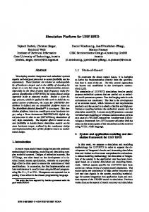
The software architecture of the Hardware-In-theLoop for autonomous system, as shown in Figure 3 composed of five independent modules. Theyare Virtual Space, Vehicle control computer (VCC), SCS (Surface control Station), HIL Bridge and Vehicle model. The bridging application uses a simulation library to communicate with virtual space and
580
INDIAN J. MAR.SCI., VOL. 41, NO. 6, DECEMBER 2012
virtual UUV navigate to its assigned destination. As a preliminary test we implemented the communication between plant model, VCC and 3D vehicle visualize (Figure 5 and Figure 6).
Fig. 5—Screenshot of virtual UUV in OpenSimulator.
Fig. 6—Trajectory Unmanned Underwater Vehicle.
connects to the embedded PC104 board, emulating the inputs and outputs from the vehicle model. VCC outputs serial data in packed binary identical to the packet produce by the vehicle space and vehicle model. It also accepts command outputs from SCS. This provides a realistic test of remaining components of the system. The virtual space forwards a raw data to VCC. The given data are in engineering unit. Therefore, the HIL Bridge application must perform reverse conversion on the data before sending it to the PC104 embedded board. Similarly the control surface position received from the embedded board is in raw format the HIL Bridge converts normalized positions to helicopter plant model. Experimental Test Results The performance of the proposed system is validated with HILS platform. Figure 4 illustrates the
Conclusion System evaluation and testing of unmanned underwater vehicle in certain environment can be tedious and time consuming. In this paper we outline a design, development of control system for unmanned underwater vehicle Along with this a testing environment for UUV is developed to validate proposed system. Complete system is run under QNX RTOS based PC104 embedded board. Through the HILS simulation the proposed approach was demonstrated and validated. As a preliminary test the virtual UUV navigated in the assigned path. In future, the complete set of control system will be tested on a proposed platform. Acknowledgement The work was supported by a grant from Korea Research Council of Fundamental Science & Technology funded by Ministry of Education, Science and Technology in 2012. References 1
2 3 4
5 6
7 8
L. N. Long, S. D. Hanford, O. Janrathitikarn, G. L. Sinsley, and J. A.Miller, “A review of intelligent systems software for autonomous vehicles, ”Computational Intelligence in Security and Defense Applications, USA, April 2007. Arkin, R.C., Behavior-Based Robotics, MIT Press, Cambridge, 1998. Meystel, A.M. and Albus, J., Intelligent Systems: Architecture, Design, Control, Wiley, New York 2001. Bekey, G.A., Autonomous Robots: From Biological Inspiration to Implementation and Control, MIT Press, Cambridge 2005. Russell, S.J. and Norvig, P., Artificial Intelligence: A Modern Approach, Prentice Hall, New Jersey, 1995. Budiyono, A. Sugama, Muljowidodo, &SaptoAdiNugroho, Dynamics analysis of AUV Sotong, paper presented at the 2nd International Conference on Underwater System Technology: Theory and Applications 2008 (USYS’08),Bali, Indonesia, 2008. QNX Operating system: http://www.qnx.com/. OpenSimulator: http://opensimulator.org/wiki/Main_Page.