412
IEEE TRANSACTIONS ON ELECTROMAGNETIC COMPATIBILITY, VOL. 46, NO. 3, AUGUST 2004
Hardware Invariant Protocol Disruptive Interference for 100BaseTX Ethernet Communications Ian Jeffrey, Colin Gilmore, Greg Siemens, and Joe LoVetri, Member, IEEE
Abstract—In this paper, we introduce a new concept that we refer to as hardware invariant protocol disruptive interference (HIPDI). Such interference would pose a severe threat as intentional EMI to the corresponding protocol for which it was designed. In this paper, we consider only the 100BaseTX Ethernet protocol over UTP CAT-5 cable which is used extensively in local-area networks. We show that low power, narrowband, differential-mode voltage levels on a 100BaseTX Ethernet twisted-pair can seriously degrade network throughput independent of the physical features of the network or the protocol interpreter hardware. Moreover, we show that the required parameters of disruptive interference can be derived from the protocol itself using a concept we call hardware aperture. The experimental results reported herein indicate that creating such interference is practically feasible and therefore, is a possible threat to existing communication networks. Index Terms—Data communication, intentional electromagnetic interference (EMI), protocols, susceptibility.
I. INTRODUCTION
U
SE OF INTERNET communications is ubiquitous in almost every industry as well as government and military agencies. Moreover, there are numerous different protocols and physical hardware implementations responsible for data-transfer worldwide such as fiber-optic links, which account for the majority of long-distance data transfer, and wired or wireless communication systems which comprise most of the local or short-distance data transfer. While previous research shows the possibility of seriously disrupting wired network communications using high-power microwave (HPM) pulses [1], such interference is often expensive to generate and rather than disrupting communications can easily crash personal computer systems. HPM is an overt threat which is usually meant to permanently damage electronic hardware [2]–[5]. The goal of this paper is to investigate the possibility of covertly effecting serious communication degradation which is relatively invariant to the hardware implementation of that communication. Specifically, we have selected the 100BaseTX Ethernet protocol operating over Category-5 (CAT-5) cables as our target protocol simply because it is a widely used network protocol. We wish to determine the possibility of using low power, radiated electromagnetic interference to severely degrade Ethernet Manuscript received July 15, 2003; revised March 14, 2004. This work was supported by a Grant from the Natural Sciences and Engineering Research Council of Canada. The authors are with the Department of Electrical and Computer Engineering, University of Manitoba, Winnipeg, MB R3T 2N2, Canada (e-mail:
[email protected]). Digital Object Identifier 10.1109/TEMC.2004.831885
communication while maintaining computer functionality in every other respect. We also wish to accomplish such communication degradation without knowing the exact physical features of the network nor the specific hardware involved. We are looking for what we call hardware invariant protocol disruptive interference (HIPDI). We will first elaborate on the HIPDI concept as well as introduce the idea of hardware aperture in Section II. Section III presents a discussion of the hardware aperture for 100BaseTX Ethernet while an overview of the experimental setup in discussed in Section IV. We next describe the configuration of the network as well as the interference used in the experiments conducted to find a HIPDI and then give the results of these experiments. II. HIPDI AND HARDWARE APERTURE While the theoretical concept of HIPDI is a simple one, disruptive interference, which is totally hardware invariant is impossible because the required radiation power level, which is a feature of the interference, will vary with the physical implementation of the network. Specifically, for a wired network, the spatial orientation of the cable will affect the amount of energy coupled into the system. If, however, the required radiation level is low enough that the shielding of the network becomes a practical impossibility we consider such interference almost or quasi-invariant to the hardware implementation and physical configuration of the network. Therefore, the research presented herein is not specifically concerned with the coupling problem (the coupling problem has been effectively studied previously; see, for example, [6]). In sum, we are looking for waveforms that will effectively disrupt Ethernet communication with minimal power: an amount of power for which it is practically feasible to generate, launch, and couple covertly into the network and have a high probability of effecting disruption. It is intuitive, that for any communication network, HIPDI could be accomplished if the energy coupled into the system was indistinguishable from actual communication data. In this manner HIPDI would be the result of simple information overload in which the hardware interpreter, the hardware device responsible for receiving (or transmitting) information, would be constantly occupied receiving the HIPDI. Although hardware interpreters are designed by many different manufacturers, they all respond to signals having parameters as specified by the protocol. Beyond interpreting the parameters required for the protocol, different hardware interpreters may function quite differently. Interference which is very distinct from communication data must immediately be rejected as possible HIPDI since physical protection techniques are available to deal with
0018-9375/04$20.00 © 2004 IEEE
JEFFREY et al.: HIPDI FOR 100BASETX ETHERNET COMMUNICATIONS
413
Fig. 1. Mapping from a 4b/5b data stream to MLT-3 signal level.
such interference (e.g., chokes). HIPDI should therefore come as close as possible to resembling data. In the practical sense, this is most easily accomplished by considering the frequency spectrum and the signal level of the data. The idea that a hardware interpreter must respond accordingly to signals defined by the protocol is what we call the hardware aperture of the protocol. Application of this concept for 100BaseTX Ethernet is presented in the following section. III. 100BASETX ETHERNET AND HARDWARE APERTURE The physical layer of the network under test is implemented using CAT-5 Unshielded Twisted Pair (UTP) cables. Such cables are specified as having a 100- characteristic impedance and are typically rated to 100 MHz although “enhanced” 350 MHz cables are available commercially. The cables we selected are of the un-enhanced 100-MHz kind. While other types of cables such as CAT-6 and CAT-5 incorporating shielded twisted pairs (STP) are available, we have selected unshielded CAT-5 due to its wide use in computer networks. CAT-5 cable is characterized by four pairs of twisted wires enclosed by a protective plastic covering. Specifically, one such pair is used to transmit information and, depending on the implementation, the same pair, or a different pair, is used to receive information (half- or full-duplex operation). The other two pair of wires have various applications depending on the implementation and are not relevant to our discussion. If a HIPDI exists for the 100BaseTX Ethernet protocol, it will be the protocol itself that indicates what sort of parameters the interference must have. The 100BaseTX Ethernet protocol is a 100 Mb/s communication scheme in which data is transmitted in differential-mode using a pair of wires, which we denote as the data pair. The 100BaseTX protocol can use separate pairs for sending and receiving, but for our purpose we consider only a single transmitter and a single receiver, in which case the transmit and receive pairs are the same (full-duplex operation). Logical data is encoded by first converting binary information to what is commonly referred to as a 4-bit-to-5-bit (4b/5b) encoding scheme [7]. Every 4 bits of data to be sent are encoded into 5 bits via a lookup table. This is done to prevent a long string of successive “1”s or “0”s in the data transmission. Once encoded by 4b/5b, the data is further encoded using the multilevel 3 (MLT-3) encoding scheme. MLT-3 functions by making , and (physically represented by use of 3 signal levels and V) and making a transition from 0 to 1 or and to . In encoding a logical 1, from signal level 0, from or MLT-3 moves to 1 if a move to was made previously and
vice-versa. In the case of a logic 0 the MLT-3 level remains the same. An example of MLT-3 encoding for an arbitrary 4b/5b encoded data-stream is shown in Fig. 1. Because the 4b/5b encoding increases 100 Mbits to 125 Mbits, data is transmitted at 125 Mbps in order to achieve the 100 Mbps data rate. Of particular interest is that this dual scheme of 4b/5b encoding and MLT-3 has the added benefit that the maximum cycle frequency (here cycle time refers to the MLT-3 level cycling once through its values from 0 and back to 0) is 31.25 MHz occurring when the data stream represents all logical ones. Of course, for any other bit stream the fundamental frequency will be below 31.25 MHz. This upper frequency limit allows 100BaseTX systems to conform to the FCC standards for radiated emissions and is a parameter characteristic of all 100BaseTX communications. One additional feature of 100BaseTX communications is that out of the sixteen 5-bit symbols that do not represent 4-bit data, an idle symbol, 11111, is selected and constantly transmitted in the absence of data. This idle signal is running at exactly 31.25 MHz under MLT-3. It is used in the absence of data transfer to verify link integrity. It is the 100BaseTX Ethernet protocol itself that defines its hardware aperture. We can immediately infer that HIPDI should be a differential interference on the data pair. The reason for this conclusion is that although common-mode interference can be converted to differential-mode due to imbalances in differential receiver hardware, such conversion is a function of the hardware implementation and therefore cannot be classified as HIPDI. In addition, common-mode interference itself can only cause hardware failure. Furthermore, for HIPDI to resemble data as much as possible, it should exist in the frequency range of the protocol below 100 MHz as limited by the use of CAT-5 cables (fundamental frequencies above this could be filtered without degradation to communication). We also know however, that based on the encoding scheme (as well as the data-packaging scheme of the protocol not discussed herein) the fundamental frequency of the data on the line will vary with time. This fact is clearly demonstrated by taking a Continuous Wavelet Transform (CWT) of typical 100BaseTX signals as they would appear being transmitted over the 100BaseTX protocol (relevant theory regarding the CWT and its application to electromagnetic interference can be found in [8] with a recent application of the CWT to EMC presented in [9]). We have applied various wavelet transforms to simulated 100BaseTX bitstreams and found that a 10th order Complex Gaussian Wavelet utilizing 60 frequency points from 1 to 100 MHz provides the sufficient time and frequency resolution. The upper frequency limit was
414
IEEE TRANSACTIONS ON ELECTROMAGNETIC COMPATIBILITY, VOL. 46, NO. 3, AUGUST 2004
Fig. 2. CWT of a 100BaseTX idle signal—normalized CWT coefficients (dB).
Fig. 3. CWT of a 100BaseTX random data file: normalized CWT coefficients (dB).
selected based on the physical limitation of the CAT-5 cable. Fig. 2 depicts the CWT of a 100BaseTX idle signal while Fig. 3 shows the CWT of a simulated set of random Ethernet data. For dB has been aesthetic reasons, any coefficient lower than set to dB. As expected, the MLT-3 idle signal has a fundamental frequency of 31.25 MHz and the simulated random data has its largest spectral components in the range of 10–50 MHz.
Fig. 2 also shows that significant energy lies in the range of 80–100 MHz, near the third harmonic of the MLT-3 idle signal. Therefore, to resemble data (or the idle signal), HIPDI should contain energy in either of these frequency bands. Both Figs. 2 and 3 exhibit a null around 62.5 MHz (although this is much more prominent in the idle signal). This is explained by the fact that MLT-3 encoding is (approximately) a square wave and square waves symmetric across 0 V are missing even
JEFFREY et al.: HIPDI FOR 100BASETX ETHERNET COMMUNICATIONS
Fig. 4.
415
Experimental test setup.
harmonics. As there is no data information contained in this part of the spectrum, we suspect that it could be very susceptible to interference since the presence of energy where it is not meant to exist could act to confuse the hardware interpreters. Based on this theoretical analysis, we can conclude that 100BaseTX Ethernet HIPDI should be differential interference having fundamental frequency in the range of the fundamental or harmonic data frequencies: 10–50, 60–70 or 80–100 MHz. This conclusion guides the experiments presented in the following sections. IV. OVERVIEW OF EXPERIMENTAL SYSTEM The experimental system consists of the following major parts: a test communication network consisting of a server and a client PC (communicating point-to-point via Ethernet for which only the interconnecting Ethernet cable is radiated); an electromagnetic interference generating system consisting of a EMCO 5317 GTEM cell (wherein the radiation of the cable takes place), a signal generator and amplifier both programmable by the control PC over the general purpose interface bus (GPIB); an interference measurement system consisting of an electromagnetic interference (EMI) receiver, two oscilloscopes and high-impedance probes; and lastly, data communication throughput monitoring software (running on a control PC). The general setup is shown in Fig. 4. A. The Network Communication and Monitoring Software To communicate using the Ethernet protocol, each of the server and client computers were equipped with server and client User Datagram Protocol (UDP) software (programmed in Java by the authors). UDP is a data-packaging protocol commonly used over Ethernet by numerous streaming audiovideo applications. It has the desirable feature that if a packet is lost or corrupt, there is no attempt to resend the information. In this way, we are able to simply send UDP data (called UDP packets) over Ethernet and monitor the throughput. The actual
UDP data is configurable in content, length, and inter-packet delay. The control PC is equipped with software for querying the throughput rate of the client and server PCs. Using the GPIB network, the process of establishing communication, monitoring throughput, setting radiation levels, and reading differential- and common-mode power levels was fully automated via the control PC. B. The Test Networks Two test networks, A and B, were used in the experiments. Network A consists of two Pentium III 667-MHz computers running the Linux operating system forming the client and server for the Ethernet transfer link. Network B consists of two Pentium II 266-MHz computers, once again running Linux. Linux, without graphical user interface, was installed on the client–server computers in order to reduce any transfer fluctuations that might be caused by maintaining a graphical user interface on these (relatively slow) machines. The hardware responsible for transmitting and receiving information over Ethernet is commonly referred to as a network interface controller (NIC). For Network A, the client and server computers each had NIC cards installed: one pair was used for the nonradiated connection to the experiment control computer, and the two other pairs for introducing variation in the hardware technology used to implement the communications (note that our purpose is not to determine the hardware susceptibility of the NIC cards themselves). For Network B, the client and server computers each had two NIC cards installed, one for the nonradiated connection and one for the radiated connection. In total, three different commercial NIC models were used for communicating over the transfer link. C. The Ethernet Cable Two lengths of 100-MHz rated CAT-5 Ethernet cable were used as the cable under test: 30 m (100 ft) or 14 m (46 ft) for Network A and 14 m for Network B.
416
IEEE TRANSACTIONS ON ELECTROMAGNETIC COMPATIBILITY, VOL. 46, NO. 3, AUGUST 2004
D. Differential-Mode Interference Generation To simulate the covert manner in which HIPDI might be exploited it was decided that remote radiation of the cable is the appropriate means of generating differential-mode interference on the cable. We could instead simply inject differential interference directly onto the cable and handle the coupling problem later, but this is not as revealing because single point injection may produce a less applicable effect than distributive injection by means of radiation. It was decided to radiate the cable in our GTEM cell and monitor the differential power induced on the data-pair. This requires that any interference that generates no reduction in information throughput must be checked in order to ensure that the interference is truly non-HIPDI rather than a coupling null (a region where little or no coupling to the cable is attained). Radiative interference is generated with the use of a signal generator capable of producing both continuous wave (CW) and amplitude modulated (AM) signals, an amplifier capable of producing 100 W of output power, and a GTEM cell. The GTEM cell is used to expose the cable to plane-wave interference and to isolate the rest of the network. The leakage from the GTEM cell into the laboratory room was measured to be minimal over the frequency of interest (a small amount of leakage was unavoidable because of the way the cable was fed through the GTEM cell). The operation of the computers was not affected by this leakage energy. E. Network Interface Cards and Network Hardware Configuration Three types of network interface cards produced by two different manufacturers were used for the experiments. All three of these NICs are peripheral component interconnect (PCI) bus based cards and are compatible with all PCs having PCI supported motherboards. The NIC selection was made simply based on availability in the commercial market. For each experiment one of the NIC pairs was selected which, in what follows, we refer to as NIC pair A, B or C. F. UDP Data Parameters Each UDP packet was selected to be a set of random data (the same random data for each packet). Due to the overhead in the java programs themselves (thread creation and packet monitoring) an inter-packet delay was set so that the transfer and receive rates were equal and maximum in the absence of interference. For Network A, a UDP packet of 200 bytes was used resulting in roughly 2800 packets per second while for Network B, a UDP packet size of 20 bytes was used resulting in roughly 1000 packets per second. V. EXPERIMENTAL INTERFERENCE CONFIGURATION Two types of interference signals were used in all tests; CW and AM. The AM modulation was set to 100% using a 15 kHz square wave. This choice was based on preliminary test results which showed that data-rate degradation was nearly invariant to AM frequencies below 15 kHz. For both CW and AM signals, discrete carrier frequencies from 1 to 100 MHz (in 1 MHz
increments) were used. This frequency range was selected for a number of reasons: first, as suggested in Section III, HIPDI should lie in the frequency range of 10–50 MHz, 60–70 MHz or 80–100 MHz. Secondly, preliminary tests conducted up to 1 GHz, showed little or no effect above 100 MHz for the power levels considered. Finally, the selected CAT-5 cable is only rated to 100 MHz and therefore, frequencies above 100 MHz cannot be considered HIPDI as the hardware implementation of the network may vary above this frequency. VI. EXPERIMENTAL PROCEDURES Two experimental procedures were performed in order to gain as much information as possible regarding the 100BaseTX protocol’s susceptibility to interference. The first set of experiments was performed on Network A and the second on Network B and these will be denoted as Experiments A and Experiments B, respectively. They are described in the following sections. A. Experiments A In the first set of experiments, we show general results with no detailed analysis of the coupling energy. In these experiments, the Ethernet cable was selected as either 30 or 14 m in length, which we will simple refer to as long and short, respectively. The cable was randomly oriented in the GTEM cell and attached to the client and server PCs. The portion of the cable outside of the cell was left unshielded and no attempt was made to reduce the common-mode component of the coupled interference. In order to monitor the differential power on the data-pair, a small portion of cable covering, roughly 5 cm in length, near the client PC, was removed in order to place a high-impedance probe across the data pair. The differential power measured by the probe was recorded using the EMI receiver shown in Fig. 4 (the power measurements taken using the EMI receiver and probe were calibrated using a signal generator). Each experiment of type A consists of four tests. A typical test consists of a single interference signal type (CW or AM), over the frequency range (1–100 MHz), where the radiation power level is adjusted in order to achieve a desired coupled power level on the data-pair (as measured using the EMI receiver and probe). The desired power levels on the data-pair chosen were 20 15 10, and 5 dBm. It was found that taking measurements using the EMI receiver and probe in this way caused no effect on data throughput in the absence of interference and was therefore assumed to have no effect on data throughput in the presence of radiation. This method does not give an accurate measurement of the differential-mode interference induced onto the cable because: 1) the Ethernet cable was left unshielded and the large common-mode current induced on the cable inductively couples to the probe and 2) we are using an unbalanced probe to measure the power on a balanced pair. While results of these experiments do not accurately show the amount of power required to produce throughput degradation, these experiments still show frequencies at which throughput degradation is possible. A set power level on the cable was achieved for each test so as to compensate for variations in cable coupling over frequency (the power level is a combination of differential- and
JEFFREY et al.: HIPDI FOR 100BASETX ETHERNET COMMUNICATIONS
TABLE I EXPERIMENTS OF TYPE A
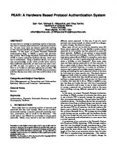
common-mode). The selected setups for each experiment are summarized in Table I. B. Experiments B For experiments of type B, the Ethernet cable selected was 14 m in length. To limit the common-mode coupling and to increase the differential-mode coupling, the cable was oriented parallel to the septum in the cross section of the GTEM. Inside the cell, a large portion of the cable sheath (approximately 2 m in length), was removed and the data pair was untwisted and separated by roughly 5 mm in order to maximize the amount of differential-mode coupled into the cable. Data throughput and the integrity of the data waveform were checked after this modification to ensure that the physical changes to the cable caused no change in performance. The portions of the cable outside of the cell were shielded and grounded to the GTEM cell and the client or server PC to reduce the common-mode radiation outside the cell and reduce the probe coupling that occurred in Experiments A. Finally, common-mode chokes were used inside the cell in order to further minimize the amount of common-mode on the cable. Each Experiment B consist of ten tests where a test consists of a single interference signal type (CW or AM), over the frequency range (1–100 MHz), each using a single radiation power level. The total experiment is simply the ensemble of the test W input results for the CW power levels of into the GTEM cell. No probing was performed during the tests, only the throughput was monitored. Afterwards, an oscilloscope was used in the absence of data to measure the differential- and common-mode voltage on the data pair. The differential voltage was probed using two high-impedance probes. The “commonmode” voltage was measured by using a single high-impedance probe from one of the data lines to the ground of the computer case. (Although, this is not truly common-mode, it is what we are calling common-mode in this paper.) Experiments B are summarized in Table II. VII. RESULTS AND ANALYSIS In order to analyze the interference results, the data is presented in a series of throughput plots. We have plotted the percent throughput as a function of frequency and either the power
417
TABLE II EXPERIMENTS OF TYPE B
level on the Ethernet cable (in the case of Experiments A) or radiation power level (in the case of Experiments B). For example, Fig. 5 shows the contour plot for Experiment A1. The darkest regions of the plot depict the regions where less than 10% throughput resulted. We see that in the frequency range of 10–18 MHz, and with a power level induced on the cable of dBm (100 mV), we have completely halted commore than munication. The white regions denote complete throughput, i.e., no degradation and will henceforth be referred to as “immunity regions.” As previously discussed, such white regions could be the result of coupling nulls or high immunity. We will now discuss the results of both types of experiments. A. Experiments A: Results As seen from Fig. 5, it is possible to disrupt communication completely under some interference signals, while others seem to have no affect on throughput. From detailed analysis of the actual interference power measured on the twisted-pair, we have confirmed that some of the immunity regions correspond directly to frequency bands in which it was not possible to couple the desired power into the network. The region around 20 MHz in Fig. 5 is a coupling null. When we compare Experiment A1 and Experiment A2 (which differ only in cable length), we see that the contours are quite different. These are shown in Figs. 5 and 6, respectively. Above 80 MHz, for instance, it was difficult to achieve any degradation in Experiment A2 using the short cable whereas with the long cable in Experiment A1 significant degradation regions are visible. We verified that at these frequencies there were no coupling nulls for either cable. We speculate that the differences between the two plots above 80 MHz is due to the probing method used to measure the induced power on the cable, as it does not sufficiently differentiate between common and differential-mode interference. Deeper degradation regions were found at lower frequencies. Comparing the results of the two experiments below 80 MHz shows that many of the coupling nulls present in Experiment A1 (e.g., 20, 48, and 52 MHz) are not present for the short cable in Experiment A2. On the other hand, Experiment A2 has nulls where A1 does not. It is well known, that different cable lengths will show resonances at different frequencies; the experiments simply confirm this. Scanning the results of Experiments A1 and A2 lead us to think that simple CW radiation in the ranges 10–50 MHz, 50–70 MHz, and 80–100 MHz may be areas where HIPDI is possible. But comparing with the results of Experiment A6, shown in Fig. 7, reveals that varying the NIC pair from A to C, over the short cable, reduces the degradation significantly.
418
IEEE TRANSACTIONS ON ELECTROMAGNETIC COMPATIBILITY, VOL. 46, NO. 3, AUGUST 2004
Fig. 5. Experiment A1—CW radiation of Network A for NIC pair A—long cable.
Fig. 6. Experiment A2—CW radiation of Network A for NIC pair A—short cable.
Specifically, in the 10 to 18 MHz region, dBm is now required to produce severe degradation compared with the dBm required for NIC pair A. Also, no degradation was achieved above 60 MHz. One possible reason for this could be that although great care was taken to maintain the cable positioning when changing NIC pairs, the orientation may have been disturbed resulting in different coupling. The other explanation is simply that some of the regions of throughput re-
duction in Experiments A1, A2 and A6 are hardware dependent. to dB of normalized Although Fig. 2 and Fig. 3 show CWT coefficient level in the range of 80–100 MHz (initially assumed to indicate significant power levels), the difference in throughput above 80 MHz shows that, at least for CW, it is not a significant aperture for HIPDI. (Results from Experiments B support this.) Results similar to Experiment A6 (NIC pair C), were obtained for NIC pair B (A4). As expected, changing the
JEFFREY et al.: HIPDI FOR 100BASETX ETHERNET COMMUNICATIONS
419
Fig. 7. Experiment A6—CW radiation of Network A for NIC pair C—short cable.
Fig. 8. Experiment A12—AM radiation of Network A for NIC pair C—short cable.
cable length made little difference to the degradation contour. This indicates that although degradation occurs within the frequency spectrum of the Hardware Aperture, variations due to the hardware are apparent. The case changes when we broaden the spectrum of the interference by adding AM. For AM interference we find much deeper and broader degradation regions. An example is shown in Fig. 8 where the results of experiment A12 are displayed. Here, the short cable
was used with NIC pair C as in experiment A6 of Fig. 6, however AM interference was used instead of CW interference. We notice immediately that in the same regions where CW interference showed degradation, AM interference shows similar degradation at a lower power level. The 10–50 MHz range (except for a null around 20 MHz) is such a region. We suspect that AM is more effective because of its broader spectrum which is more similar to the spectrum of 100BaseTX data than simple CW.
420
IEEE TRANSACTIONS ON ELECTROMAGNETIC COMPATIBILITY, VOL. 46, NO. 3, AUGUST 2004
Fig. 9. Experiment B1—CW radiation of Network B for NIC pair A—short cable, 20 W forward power.
As the theory predicted this whole range of frequencies appears to be a good candidate for HIPDI. Isolated coupling nulls in this region will be dependant on cable length and therefore a successful HIPDI would have to span this whole region. Though not shown, this was confirmed by very similar results when NIC pairs A and B were exposed to AM interference. For each NIC pair, the predicted frequency ranges of 10–50 MHz and 60–70 MHz are susceptible to AM interference while the susceptibility of the 80–100 MHz band seems to be hardware dependent. It should be noted that for all experiments of type A degradation occurred only to the throughput and no effect was detectable in the operation of the server and client computers themselves. That is to say, all non-network programs running on these computers always executed normally. Therefore, although the HIPDI we are searching for is differential-mode, it seems that common-mode and differential-mode interference can be used to degrade network throughput undetectable to the end user, but only differential-mode can be hardware independent.
B. Experiment B: Results As discussed in Section VI-A, the probing method used to measure the induced cable interference for Experiments A does not allow us to differentiate between common- and differential-mode. Because we have theorized that a true HIPDI for 100BaseTX Ethernet should be differential-mode, we adopted the more accurate probing technique detailed in Section VI-B. In these tests, for every significant region indicated by the interference results, accurate measurements of the differential and common-mode cable interference were taken in the absence of data.
Figs. 9 and 10 show the results of Experiment B1 for 20 W, and 60 W of forward power (approximately 30 and 55 V/m, respectively, at the location of the cable inside the cell). Disruption occurred at such low power levels that contour plots are not as revealing as they are for Experiments A. From the figures we see throughput disruption over a wide range of frequencies as in Experiments A. In this case, frequencies up to 17 MHz were found to be coupling nulls. In Experiments A we saw very little disruption above 60 MHz, but in these tests, where the differential power levels were increased, we see disruption to 100 MHz. In particular at both 33 MHz and 65 MHz it is possible to generate large throughput reduction with as little as 20 W of forward power. Although we show only CW results, the difference when AM was used is similar to the difference between CW and AM for Experiments A. More careful analysis of these results shows some very interesting properties. Tables III and IV summarize the main features of the CW test at frequencies of interest. Table III shows frequencies where disruption occurred (where the lowest power level at each frequency denotes the minimum required interference power for disruption to occur) and Table IV shows frequencies (other than the null below 17 MHz) where disruption was not possible up to 100 W of forward power. Overall, for the lowest forward power level, the most significant reduction occurred near 33, 65, 72, and 86 MHz. Whether or not this is strictly due to differential-mode, is revealed by the tables. The maximum common-mode induced on the cable was 2.56 V pk-pk at 33 MHz (subsequent voltage levels indicate pk-pk values), whereas the minimum common-mode level was less than 0.5 V. The remaining frequencies of Table III (18, 54, 67, 81, 96) correspond to throughput reduction above a certain radiation level and no reduction below that radiation level. In all of these cases, the common-mode does not exceed 4.8 V and is
JEFFREY et al.: HIPDI FOR 100BASETX ETHERNET COMMUNICATIONS
Fig. 10.
421
Experiment B1: CW radiation of Network B for NIC pair A; short cable, 60 W forward power. TABLE III EXPERIMENT B1 SUSCEPTIBLE FREQUENCIES
TABLE IV EXPERIMENT B1 INSUSCEPTIBLE FREQUENCIES
this level of differential-mode interference was seen at the onset of throughput reduction in all cases except for 65 MHz where only 142 mV was required. From Table IV, even more inferences are made. The four frequencies correspond to areas of zero throughput reduction up to 100 W. The frequencies 24 and 58 MHz were not capable of generating 340 mV of differential-mode. In order to determine whether or not degradation is due to common-mode, we note that at 38 MHz which is inside our Hardware Aperture, the common-mode was above 9 V, the highest at any of the selected test frequencies, and no disruption occurred. This is merely an indication that common-mode coupling is not always a cause of throughput disruption and leads us to believe that, at least at this frequency, high-level common-mode interference has no effect. Finally, at 38 and 92 MHz, more than 790 mV of differential-mode was on the pair and no failure occurred. We expected to see an effect at both of these frequencies but this did not show up in our results. For 92 MHz this is consistent with the results of Experiments A1, A2, and A6 which showed that interference in this spectrum might not have a significant aperture for HIPDI. At 38 MHz, throughput disruption was possible when the interference was changed from CW to AM. This once again suggests that AM interference is a more suitable HIPDI candidate.
VIII. CONCLUSION
typically 1–2 V. For the differential-mode, it seems that approximately 340 mV is the threshold for disruption to occur. In fact,
In this paper, we have introduced a new concept, HIPDI. The existence of HIPDI would pose a severe threat, if implemented as intentional EMI, to the corresponding protocol for which it was designed. The reason for its severity is that little can be done to guard against it or to detect it as such interference has properties similar to the protocol itself. These properties can be
422
IEEE TRANSACTIONS ON ELECTROMAGNETIC COMPATIBILITY, VOL. 46, NO. 3, AUGUST 2004
theoretically extracted by considering the protocol and properties of the protocol (such as frequency) that make interference feasible. We have shown that narrowband differential-mode voltage levels as low as 142 mV on a 100BaseTX Ethernet twisted-pair can seriously degrade network throughput. We have verified that the 100BaseTX protocol is susceptible to CW radiation with frequencies from 10–50 MHz and AM radiation in the frequency ranges of 10–50 MHz, 60–70 MHz, and 80–100 MHz (in all test cases when the problem of sufficient coupling is ignored) We suspect that AM interference causes greater throughput degradation as its broader spectrum resembles data better than CW. As our experiments were designed to produce maximum differential-mode interference in the cable, there is no guarantee that, given an arbitrary network, it is feasible to generate this amount of interference covertly. CAT-5 cable is specifically designed to suppress radiation resulting from differential-mode current and by consequence is therefore well-protected against differential-mode interference. We feel, however, that the approach presented herein is of great importance and can be applied to any number of protocols for any type of network. Specifically, future work will move toward covert disruption of wireless networks in which shielding is not feasibly possible. Finally, though we have no formal proof that the throughput reductions achieved were independent of the hardware implementation (if such a formal proof exists), we can conclude that communication on every network we have tested fails in the presence of HIPDI-type radiation that does not disrupt computer functionality in other regards. ACKNOWLEDGMENT The authors would like to gratefully acknowledge the advice on Ethernet communications given by R. McLeod of the University of Manitoba. Programming advice and network communication troubleshooting was also provided by J. Berkes, D. Schaub, and T. Czyrnyj. REFERENCES [1] C. Mojert, D. Nitsch, H. Friedjoff, J. Maack, F. Sabath, M. Camp, and H. Garbe, “UWB and EMP susceptibility of microprocessors and networks,” in Proc. 14th Int. Zürich Symp. EMC, Zürich, Switzerland, Feb. 20–22, 2001, pp. 47–52. [2] I. Kohlberb and R. J. Carter, “Some theoretical considerations regarding the susceptibility of information systems to unwanted electromagnetic signals,” in Proc. 14th Int. Zürich Symp. EMC, Zürich, Switzerland, Feb. 20–22, 2001, pp. 41–46. [3] F. Sonnermann, “Susceptibility investigations of high-power EM-fields on electronic systems,” in Proc. 15th Int. Zürich Symp. EMC, Zürich, Switzerland, Feb. 18–20, 2003, pp. 115–120. [4] D. Nitsch, F. Sabath, H. U. Schmidt, and C. Braun, “Comparison of the high power microwave and ultra wide band susceptibility of modern microprocessor boards,” in Proc. 15th Int. Zürich Symp. EMC, Zürich, Switzerland, Feb. 18–20, 2003, pp. 121–126. [5] M. A. Messier, K. S. Smith, W. A. Radasky, and M. J. Madrid, “Response of telecom protection to three IEC waveforms,” in Proc. 15th Int. Zürich Symp. EMC, Zürich, Switzerland, Feb. 18–20, 2003, pp. 127–132. [6] C. R. Paul, Analysis of Multiconductor Transmission Lines. New York: Wiley, 1994.
[7] IEEE Standard for Information Technology—Telecommunications and Information Exchange Between Systems—Local and Metropolitan Area Networks—Specific Requirements—Part 3: Carrier Sense Multiple Access with Collision Detection (CSMA/CD) Access Method and Physical Layer Specifications.. IEEE std. 802.3-2002. [8] T. K. Sarkar and C. Su, “A tutorial on wavelets from an electrical engineering perspective, Part 2: The continuous case,” IEEE Antennas Propagat. Mag., vol. 40, pp. 36–49, Dec. 1998. [9] B. Kordi, J. LoVetri, and G. Bridges, “Using wavelets to characterize time-frequency features of electromagnetic coupling problems,” in Proc.ANTEM’2002, Quebec, Canada, July 31–Aug. 2 2002, pp. 115–120. [10] J. Postel, Ed., Transmission Control Protocol—DARPA Internet Program Protocol Specification. Los Angeles, CA: USC Inform. Sci. Inst., Sept. 1981. RFC 793. [11] J. Postel, Ed., User Datagram Protocol: USC Inform. Sci. Inst., Aug. 1980. RFC 768.
Ian Jeffrey received the B.Sc. degree in computer engineering (with distinction) from the University of Manitoba, Winnipeg, Canada in 2002, where he is currently working toward the M.Sc. degree in the fields of electromagnetic compatibility, ground-penetrating and through-wall radar, signal and image processing and computational electromagnetics. Mr. Jeffrey currently holds a Natural Sciences and Engineering Research Council of Canada Postgraduate Scholarship.
Colin Gilmore received the B.Sc. degree in electrical engineering (with distinction, and receiving the gold medal) from the University of Manitoba, Winnipeg, Canada in 2002, where he is currently working toward the M.Sc. degree in the fields of ground-penetrating and through-wall radar, signal and image processing and inverse scattering. Mr. Gilmore currently holds a Natural Sciences and Engineering Research Council of Canada Postgraduate Scholarship.
Greg Siemens is currently working toward the B.Sc. degree in electrical engineering from the University of Manitoba, Winnipeg, Canada. He is currently working in the fields of throughwall radar, field-probe design and microwave system design. Mr. Siemens held, from 2000 to 2003, a Natural Sciences and Engineering Research Council of Canada Undergraduate Scholarship.
Joe LoVetri (M’91) received the Ph.D. degree in electrical engineering from the University of Ottawa, ON, Canada, in 1991. From 1991 to 1999, he was an Associate Professor in the Department of Electrical and Computer Engineering, University of Western Ontario, Canada. He is currently a Professor in the Department of Electrical and Computer Engineering, University of Manitoba, Winnipeg, Canada. His main research interests are in time-domain CEM, modeling of EMC problems, GPR, and inverse imaging techniques.