tual realization as well as the design-flow which led to this development, including C software simulation, full-custom design and automated VHDL-based ...
HARDWARE REALIZATION OF A HAMMING NEURAL NETWORK WITH ON-CHIP LEARNING Alexandre Schmid, Yusuf Leblebici and Daniel Mlynek Swiss Federal Institute of Technology (EPFL) Integrated Systems Center (C3i) CH-1015 Lausanne, Switzerland ABSTRACT
x1 y1
yn Output Buffers
xm
{
This paper addresses the mixed analog-digital hardware implementation of a Hamming artificial neural network with on-chip learning. The developed integrated circuit architecture consists of a charge-based variable-weight neural network, and a digital module implementing the chip control, as well as the on-chip learning algorithm as a hardwareoriented adaptation of the well-known error-correction algorithm. Both the analog and the digital parts interact with each other to perform a pattern recognition task. A dedicated digital memory unit acts as the interface to temporarily hold the newly processed weights. We describe the actual realization as well as the design-flow which led to this development, including C software simulation, full-custom design and automated VHDL-based synthesis.
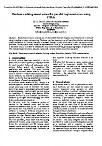
Quantifier Subnet
Discriminator Subnet
Figure 1: Schematic description of a Hamming network. 1. INTRODUCTION 2. CIRCUIT ARCHITECTURE Hardware realization of artificial neural networks aims at efficiently accelerating the processing speed of neural network specific tasks such as pattern classification, system control, and function predictions. Another aim is to increase the autonomy of systems to be integrated as specialized units into larger, neuro-computer based modular architectures, as well as into intelligent autonomous systems. This paper outlines the architecture and operation of a Hamming neural network classifier with on-chip learning ability. The Hamming network [1] is a two-layer feed-forward network (see Fig. 1) with the ability to classify noise corrupted patterns, which has the property of always converging toward one of the patterns that was stored during a training phase, prior to the classification (recall) phase. The first layer known as the quantifier subnet computes the Hamming distance between the input pattern to be recognized (classified) and the patterns stored in the network as neuron’s weight values. The second layer is the discriminator subnet which selects the first-layer neuron with highest amplitude response as the winner neuron : the one with the smallest Hamming distance to the current input pattern.
The overall circuit architecture is a mixed analog-digital realization (see Fig. 2) [2] allowing a flexible and straightforward design-flow with reusability properties, while keeping the objective of efficient and compact design. It is well known that small silicon area and fast processing speed are the most relevant characteristics of analog VLSI circuits. Their drawbacks are in terms of sensitivity to noise and physical parameter mismatches, as well as difficulty in obtaining and storing large precision values. On the other hand, purely digital realizations exhibit better immunity to noise, allow easier and more flexible automation of the design process, and support a simpler interfacing with other digital units. One drawback of this approach is the limited, but well defined precision associated to the quantification of all processed values. The Hamming network is realized as an analog module composed of a primary artificial neural network layer (ANN) of charge-based neurons to perform the weighted sum of inputs, which drives a MOS-based WTA unit [3] to carry out the classification task. of complexity n
O (
n
0-7803-4455-3/98/$10.00 (c) 1998 IEEE
�
n
)
), as the same input vector component ( the upper capacitor plates are tied together to build up the dendritic row. The capacitor values associated with each synapse are chosen as , where and (unit capacitance) = 17 fF in our realization. The capacitors are realized by comb-shaped POLY1-POLY2 overlaps resulting in exact integer multiples of the unit capacitance. Dummy capacitors are included in the architecture in order to equalize the total row capacitance, which is required for proper WTA operation. The 4-bit precision is not dictated by any limitation of the circuit technique; it was validated by careful simulations to perform satisfyingly in the pattern classification task. The noise immunity of the device is improved by a grounded MET1 shield on top of the capacitances. V
;
j
=
1
;
2
;
:
:
:
;
m
j
DIGITAL
n
C
=
2
C
i
chip ctrl
n
=
0
;
�
�
�
;
3
u
C
ANN clk
u
chip ctrl master clk load ζ
ctrl weights
weights clk weights weights
result
data ctrl threshold
ANN : quantification
V ref
ANALOG
f
f
f
f
f
f
f
f
f
f
f
f
Φ1
3. HAMMING NETWORK INTEGRATION ISSUES For the design of the Hamming network, we use a modified, adaptable weights version of the architecture first presented in [4]. Each of the neurons in the primary layer (see Fig. 3) is composed of several charge-based synapses along a common dendrite. One synapse (see Fig. 4) is made of four binary weighted capacitors as well as four memory latches to support programmability of the weights. The bottom capacitor plates of one synapse (see Fig. 4 top) receive
Φ5
Φ4
n1
Vi
Figure 2: Block-diagram of the implemented architecture. The Circuit Control Unit (CCU), Clock Generation Unit (CGU) and On-Chip Learning Unit (OLU) have been realized as purely digital units. Full-custom design methodology was applied to the design of all analog parts as well as to the design of the Multipurpose Memory Unit (MMU), which is the data interface between the analog and the digital parts, and also acts as a test structure. Significant emphasis was given to the development of macro-modules with a high degree of repetability in order to easily regenerate the circuit by the means of parametrizable scripts. On the other hand, the digital parts were first designed and functionally validated in a high-level hardware description language (VHDL), to be synthesized and integrated as standard cells by a placement and routing software tool. Cell-based high-level synthesis offers a significant reduction of the design time and a technology independent development process for the relatively small cost (in our application at least) of reduced area efficiency.
WTA : discrimination V DD 2 Φ1
ni
nn
ne Φ3
Φ1
Φ2 V1
V θ
Vm
Vj
PRECHARGE Φ1 EVALUATION Φ2 WTA PULL-DOWN Φ3 WTA PULL-UP Φ4 RESULT SAMPLE Φ5
Figure 3: Gate-level description of the Hamming network. The ANN operation requires five locally generated clock signals as illustrated in Figure 3. The quantification and phase starts by precharging the synaptic lines to the rows to on . The evaluation takes place on by applying a new pattern on the lines, which will perturbate each row voltage according to Equation 1, depending on the degree of matching between the new input data and the previously stored weights. V
D
V
R
�
e
f
=
2
D
�
1
2
� �
m
X
V 1
D
V
R
=
i
V
r
+
e
C
f
i
V
j
,
j
D
(1)
n
C
t
2
o
t
j
=
1
Here stands for the dendritic voltage after capacitive is the analog input voltage on line perturbation of row i; is the total capacitance on one row, including parj; V
R
i
V
j
C
t
o
t
0-7803-4455-3/98/$10.00 (c) 1998 IEEE
grated in the OLU (see Equation 3). The value is dictated to the system by the external supervisor controller to allow more flexibility than a hard-wired solution. �
dendrite 34fF
17fF 4 1 bit memory transmission gate
VRi
68fF
136fF w
Vj
Vj
(
n
+
1
)
=
w
(
n
)
+
�
[
d (
n
)
,
y (
n
)
]
x
(
n
)
(2)
Here stands for the weight vector, for the input vector, is the expected output and the actual neuron output result, is the learning rate, is the time increment. w
Vj
x
d
y
�
n
VRi
w
(
n
+
1
)
=
w
(
n
)
�
(3) �
where command lines
34fF
68fF �
=
�
[
d (
n
�
Figure 4: Top : circuit schematic of one synapse. Bottom : layout of two comb-shaped capacitors in the same synapse. is the synaptic capacitance of beasitic capacitances; tween row i and line j. The discrimination phase starts on the rising edge of , that sets all dendritic voltages into competition; the winner as the selection of the neuron selection is performed on with highest dendritic voltage. The classification result is at the ouput. sampled on The developed architecture operates in two distinctive modes, the training mode and the forward processing mode (recall) in which the ANN and WTA units assume different tasks. During the training phase each of the neurons (one at a time) has its weights updated each time its answer to the input vector is wrong. This answer is given by comparison of the dendritic voltage after perturbation against an external by the WTA, which acts as a two-input threshold level voltage comparator to perform the non-linear hard-limiting activation function. While training one neuron into recognizing a specific pattern, all other neurons are being set in idle state in order to avoid unwanted perturbation of the process. In forward processing mode however, all the neurons are active and have their dendritic voltages perturbed by the input pattern. The WTA then acts as a multiport sense amplifier that will raise the voltage of the winner and pull down to ground the dendritic voltages of all other neurons. C
i
j
�
3
�
4
�
5
V
�
4. A HARDWARE-ORIENTED LEARNING ALGORITHM The well known error-correction learning rule (see Equation 2) [5] was implemented in order to perform training of the ANN by updating its weights. A hardware-friendly adaptation of this algorithm, taking into account the requirement of a Hamming network for binary input vectors is inte-
)
=
,
0
y (
n
)
or if
]
x
x
=
(
n
)
if
x
=
1
j
0
j
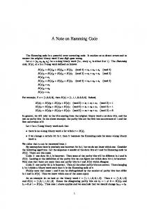
A simulation software was developed in C language to validate the architecture as well as the algorithms on a pattern classification application. The model of neuron that was implemented takes all significant characteristics of the charge-based circuit technique into account. The architecture proved to work efficiently on classifying patterns belonging to the training set, as well as on generalizing on unseen vectors. Figure 5 illustrates a ( )-bit pattern recognition application. The patterns to be recognized were chosen so as to have a relatively low degree of correlation, since the number of input pixels is relatively small in this realization. 3
�
3
5. HARDWARE REALIZATION An integrated hardware implementation of the described architecture was realized using the AMS (Austria Micro Systems) CMOS 0.8 micron technology (see Fig. 6). A network consisting of 20 neurons, each with 10 variableweight synapses, was integrated. The die size is less than , while the active chip area (including ANN, learning-supervision unit, peripheral units and clock gener. Several test structures were also inator) is less than cluded on chip, to be packaged into a 100 PGA comprising several test pins. The small area of this realization confirms the area efficiency of our mixed analog-digital approach. The test stategy included an extension of the VHDL model as well as the use of UNIX tools to automatically generate the test vectors into the appropriate format. An HP82000 ASIC tester was used for the low-end circuit test. All the constituting parts could be succesfully validated. The test of the whole circuit requires the integration on a board including a soft-programmed microcontroller, thus building up a real-time interactive environment. Our modular architectural approach gives us high confidence for this further test, which has to be considered as part of the developement of a specialized neuro-computer peripheral unit. 2
1
3
m m
2
5
m m
0-7803-4455-3/98/$10.00 (c) 1998 IEEE
PAT. 1 PAT. 2 PAT. 3 PAT. 4 PAT. 5 PAT. 6 PAT. 7 PAT. 8 PAT. 9 A
W TA
B
ANN C
D E
1 2 3 0 3 1 0 1 2
15 0 15 13 0 14 13 13 12 4 15 2 8 0 0 14 14 8 0 15 0 14 3 12 0 6 1 15 15 15 14 3 0 14 3 0 14 0 14 14 1 11 1512 13 4 15 0 14 14 8 8 0 0 1000
F IGURE A B C D E
2 1 3 3 0 1 3 2 0
2 2 1 4 0 2 1 2 3 0 2 4 4 3 0 1 3 2 0 0 4 3 1 4 4 1 2 4 1 0 2 3 1 4 3 1
105 0
1050
900
900
900
3 4 2 1 0 2 4 0 1
0 3 2 0 2 1 1 4 3
900
MM U
CCU
C GU
2 1 1 4 3 2 0 4 2
OL U
9 14 14 0 0 9 9 8 8 0 3 14 0 4 14 11 3 9 0 0 7 8 14 14 7 11 9 900
CL K DVR
1000
L EGEND Noiseless patterns to be recognized PAT. 1 TO PAT. 9 Noisy patterns Initial weights Resulting weights Threshold �
Figure 5: Simulation of the implemented pattern recognition algorithms. 6. CONCLUSION We have demonstrated in this paper the design methodology as well as the silicon integration of a charge-based Hamming artificial neural network. The neural network has a full-custom analog realization, while its learning-supervising unit has a VHDL-based digital realization, which ensures efficient area optimization and fast, automatizable designflow. Further developments include board-level integration as a specialized neuro-computer peripheral unit, automatization of the design-flow into as a ANN silicon compiler, as well as the extension of the demonstrated principles to larger ANN architectures. 7. REFERENCES [1] Richard P. Lippmann, An Introduction to Computing with Neural Nets, IEEE ASSP Magazine , April 1987.
U NIT WTA ANN CGU OLU CCU MMU CLK DVR
F UNCTION Winner-Take-All Unit Artificial Neural Network, Hamming capacitor matrix Clock Generation Unit On-Chip Learning Unit (error correction) Chip Control Unit Multipurpose Memory Unit Clock Drivers
A/D A A D D D D D
Figure 6: Microphotograph of the integrated circuit, showing the main units of the mixed analog-digital architecture. Learning Ability, Proceedings of the 5th European Congress on Intelligent Techniques & Soft Computing EUFIT’97, Aachen, Germany, September 1997. [3] Z. Sezgin G¨unay and Edgar S´anchez-Sinencio, CMOS Winner-Take-All Circuits: A Detail Comparison, Proceedings of the 1997 International Symposium on Circuits and Systems ISCAS’97, Hong Kong, 1997. [4] U˘gur Cilingiro˘glu, A Charge-Based Neural Hamming Classifier, IEEE Journal of Solid-State Circuit, Vol. 28, No. 1, January 1993. [5] Simon Haykin, Neural Networks : A Comprehensive Fundation, Macmillan College Publishing Company, New-York, 1994.
[2] Alexandre Schmid, Yusuf Leblebici and Daniel Mlynek, A Charge-Based Artificial Neural Network with On-Chip
0-7803-4455-3/98/$10.00 (c) 1998 IEEE