In this paper a hardware implementation of a neural network using Field
Programmable Gate Arrays (FPGA) is presented. A digital system architecture is ...
HARDWARE IMPLEMENTATION OF A FEEDFORWARD NEURAL NETWORK USING FPGAs Aydoğan Savran, Serkan Ünsal Ege University, Department of Electrical and Electronics Engineering
[email protected],
[email protected] Abstract In this paper a hardware implementation of a neural network using Field Programmable Gate Arrays (FPGA) is presented. A digital system architecture is designed to realize a feedforward multilayer neural network. The designed architecture is described using Very High Speed Integrated Circuits Hardware Description Language (VHDL) and implemented in an FPGA chip. The design is verified on an FPGA demo board.
I. INTRODUCTION Artificial Neural Networks have been widely used in many fields. A great variety of problems can be solved with ANNs in the areas of pattern recognition, signal processing, control systems etc. Most of the work done in this field until now consists of software simulations, investigating capabilities of ANN models or new algorithms. But hardware implementations are also essential for applicability and for taking the advantage of neural network’s inherent parallelism. There are analog, digital and also mixed system architectures proposed for the implementation of ANNs. The analog ones are more precise but difficult to implement and have problems with weight storage. Digital designs have the advantage of low noise sensitivity, and weight storage is not a problem. With the advance in programmable logic device technologies, FPGAs has gained much interest in digital system design. They are user configurable and there are powerful tools for design entry, syntheses and programming. ANNs are biologically inspired and require parallel computations in their nature. Microprocessors and DSPs are not suitable for parallel designs. Designing fully parallel modules can be available by ASICs and VLSIs but it is expensive and time consuming to develop such chips. In addition the design results in an ANN suited only for one target application. FPGAs not only offer parallelism but also flexible designs, savings in cost and design cycle.
Networks Processing Toolbox. Then calculated weights are written to a VHDL Package file. This file, along with other VHDL coding is compiled, synthesized and implemented with Xilinx ISE software tools. Simulations are made with ModelSim. Finally the design is realized on a Digilent DIIE demo board having the Xilinx FPGA chip. III. DATA REPRESENTATION Before beginning a hardware implementation of an ANN, a number format (fixed, floating point etc.) must be considered for the inputs, weights and activation function. And also the precision (number of bits) should be considered. Increasing the precision of the design elements significantly increases the resources used. Accuracy has a great impact in the learning phase; so the precision of the numbers must be as high as possible during training. However during the propagation phase, lower precisions are acceptable [5]. The resulting errors will be small enough to be neglected especially in classification applications [1, 3, 4]. In the XOR problem we applied, the input space is between –1 and 1. The training resulted in weights residing between –2 and 2. We chose 8-bit precision for the system to cover the [-2,2) range, resulting in a precision of 1/64. Table 1 shows various numbers in this range and their 8-bit representation. To represent negative numbers, 2’s complement method is used. Table 1. Data representations. Number
Representation
-2
10000000
-1
11000000
0
00000000
0.015625
00000001
II. APPLICATION
0.734375
00101111
The application selected in this work is a three input XOR problem. A 3-5-1 backpropagation network (three neurons in the input layer, five neurons in the hidden layer and one neuron in the output layer) is implemented on a XILINX Spartan II chip with 200,000 typical gate count. First the network is trained in software using MATLAB Neural
1
01000000
1.984375
01111111
IV. NETWORK ARCHITECTURE
Layer Architecture
Implementation of a fully parallel neural network is possible in FPGAs. A fully parallel network is fast but inflexible. Because; in a fully parallel network the number of multipliers per neuron must be equal to the number of connections to this neuron. Since all of the products must be summed, the number of full adders equals to the number of connections to the previous layer minus one. For example in a 3-5-1 network the output neuron must have 5 multipliers and 4 full adders while the neurons in the hidden layer must have 3 multipliers and 2 full adders. So different neuron architectures have to be designed for each layer. Because multipliers are the most resource using elements in a neuron structure, a second drawback of a fully parallel network is gate resource usage. Krips et. al. [3] proposed such architecture.
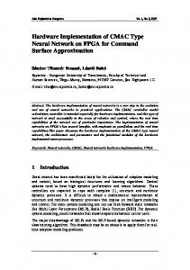
In our design an ANN layer has one input, which is connected to all neurons in this layer. But previous layer may have several outputs depending on the number of neurons it has. Each input to the layer coming from the previous layer is fed successively at each clock cycle. All of the neurons in the layer operate parallel. They take an input from their common input line, multiply it with the corresponding weight from their weight ROM and accumulate the product. If the previous layer has 3 neurons, present layer takes and processes these inputs in 3 clock cycles. After these 3 clock cycles, every neuron in the layer has its net values ready. Then the layer starts to transfer these values to its output one by one for the next layer to take them successively by enabling corresponding neuron’s three-state output. The block diagram of a layer architecture including 3 neurons is shown in Figure 2.
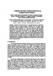
Neuron Architecture In this work we chose multiply and accumulate structure for neurons. In this structure there is one multiplier and one accumulator per neuron. The inputs from previous layer neurons enter the neuron serially and are multiplied with their corresponding weights. Every neuron has its own weight storage ROM. Multiplied values are summed in an accumulator. The processes are synchronized to clock signal. The number of clock cycles for a neuron to finish its work, equals to the number of connections from the previous layer. The accumulator has a load signal, so that the bias values are loaded to all neurons at start-up. This neuron architecture is shown in Figure 1. In this design the neuron architecture is fixed throughout the network and is not dependent on the number of connections.
Figure 1. Block diagram of a single neuron. The precision of the weights and input values are both 8 bits. The multiplier is an 8-bit by 8-bit multiplier, which results in a 16-bit product, and the accumulator is 16-bits wide. The accumulator has also an enable signal, which enables the accumulating function and an out_enable signal for its three-state outputs. Here the multiplier has a parallel, non-pipelined, combinational structure, which is generated by Xilinx Logicore Multiplier Generator V5.0 [7].
Figure 2. Block diagram of a layer consisting of 3 neurons. Since only one neuron’s output have to be present at the layer’s output at a time, instead of implementing an activation function for each neuron it is convenient to implement one activation function for each layer. In this layer structure pipelining is also possible. A new input
pattern can enter the network while another is propagating through the layers. Activation Function The activation function is implemented by means of lookup tables. The look-up table’s input space is designed so that it covers a range between –8 and +8. In our data representation system this range corresponds to 10 bits. So a 1024x8 ROM is needed to implement the activation function’s look-up table. We used Xilinx Logicore’s Single-Port Block Memory to implement this ROM efficiently in the target Spartan FPGA. The contents of the ROM are prepared in MATLAB and written to a memory initialization file in a special format, which Xilinx’s core generator can read. Network Architecture The control signals in the system are generated by a state machine. This state machine is responsible of controlling all of the operations in the network. First it activates the load signals of the neurons and the neurons load their bias values. Then hidden layer is enabled for 3 clock cycles, and then the output layer consisting of a single neuron is enabled for 5 clock cycles. Out enable signals are also activated by this state machine. The state machine is designed using generic VHDL coding so that it can easily be applied to different network configurations. The state machine generates weight ROM addresses in a priory determined sequence so that same address lines can be used by all of the neurons in the system. Input RAM also uses this address line. Once the input RAM is loaded by input values using the switches on the board, the propagation phase starts and the output of the network is displayed. The block diagram of the network is shown in Figure 3.
V. IMPLEMENTATION RESULTS The FPGA equipped chip in our demo board is a Xilinx SpartanII 2s200epq208-6. This chip has 2352 slices and 14 block RAMs. A slice is a logic unit, which includes two 4-input look-up tables (LUT) and two flip-flops. The resource usage of a single neuron, activation function and state machine is shown in Table 2. In Table 3 the resource usage of the whole design is shown. To emphasize the networks resource usage, we excluded the display interface’s and input RAM’s resource usages in these tables. Table 2. Resource usage of the design elements. Activation State Neuron Function Machine Number of 12 12 Slices Number of 22 11 Slice Flip-Flops Number of 23 17 4-input LUTs Number of 2 Block RAMs Table 3. Resource usage of the design elements. 91 Number of Slices 151 Number of Slice Flip-Flops 161 Number of 4-input LUTs 4 Number of Block RAMs
Figure 3. Block diagram of the 3-5-1 network.
VI. CONCLUSION This paper has presented the implementation of neural networks by FPGAs. The proposed network architecture is modular, being possible to easily increase or decrease the number of neurons as well as layers. FPGAs can be used for portable, modular, and reconfigurable hardware solutions for neural networks, which have been mostly used to be realized on computers until now. With the internal layer parallelism we used, it takes only 10 clock cycles for the applied 3-5-1 network to calculate its output. If this network was realized with a microprocessor it would take more than one hundred clock cycles to make all the 20 multiplications and 20 summations. Because neural networks are inherently parallel structures, parallel architectures always result faster than serial ones. In our design the clock period can be as low as 20ns taking the propagation delays in the FPGA into account. FPGA technologies are fairly new and rapidly advancing in gate count and speed. We think that they are the best candidates in neural network implementations among the other alternatives. VII. REFERENCES 1.
2.
3.
4.
5.
6.
7. 8.
J.J. Blake, L.P. Maguire, T.M. McGinnity, B. Roche, L.J. McDaid, “The Implementation of Fuzzy Systems, Neural Networks using FPGAs”, Information Sciences, Vol. 112, pp.151-168, 1998. C. Cox and W. Blanz, “GANGLION-A Fast FieldProgrammable Gate Array Implementation of a Connectionist Classifier,” IEEE Journal of SolidState Circuits, Vol. 27, No. 3, pp288-299, 1992. M. Krips, T. Lammert, and Anton Kummert, “FPGA Implementation of a Neural Network for a Real-Time Hand Tracking System”, Proceedings of the first IEEE International Workshop on Electronic Design, Test and Applications, 2002. H. Ossoinig, E. Reisinger, C. Steger, and Reinhold Weiss. “Design and FPGA-Implementation of a Neural Network.” Proceedings of the 7th International Conference on Signal Processing Applications & Technology, pp 939-943, Boston, USA,October 1996. M. Stevenson, R. Weinter, and B. Widow, “Sensitivity of Feedforward Neural Networks to Weight Errors,” IEEE Transactions on Neural Networks, Vol. 1, No. 2, pp 71-80, 1990. R. Gadea, J. Cerda, F. Ballester, A. Mocholi, “Artificial neural network implementation on a single FPGA of a pipelined on-line backpropagation”, Proceedings of the 13th International Symposium on System Synthesis (ISSS'00), pp 225-230, Madrid, Spain, 2000. Xilinx, “Logicore Multiplier Generator V5.0 Product Specification,” San Jose, 2002. Xilinx, “Logicore’s Single-Port Block Memory for Virtex, Virtex-II, Virtex-II Pro, Spartan-II, and Spartan-IIE V4.0,” San Jose, 2001.