vi_x, vi_y, vi_z, vj_x, vj_y, vj_z, hi, hj, fi, fj, ci, cj, pi, pj, rhoi, rhoj, mj. Fig. 6. Data flow graph of SPH pressure force calculation (with assigned node number in each ...
Hardware Task Scheduling Optimizations for Reconfigurable Computing Miaoqing Huang, Harald Simmler, Proshanta Saha, and Tarek El-Ghazawi NSF Center for High-Performance Reconfigurable Computing (CHREC) Department of Electrical and Computer Engineering, The George Washington University {mqhuang,simmler,sahap,tarek}@gwu.edu Abstract—Reconfigurable Computers (RC) can provide significant performance improvement for domain applications. However, wide acceptance of today’s RCs among domain scientist is hindered by the complexity of design tools and the required hardware design experience. Recent developments in hardware/software co-design methodologies for these systems provide the ease of use, but they are not comparable in performance to manual co-design. This paper aims at improving the overall performance of hardware tasks assigned to FPGA. Particularly the analysis of inter-task communication as well as data dependencies among tasks are used to reduce the number of configurations and to minimize the communication overhead and task processing time. This work leverages algorithms developed in the RC and Reconfigurable Hardware (RH) domains to address efficient use of hardware resources to propose two algorithms, Weight-Based Scheduling (WBS) and Highest Priority First-Next Fit (HPF-NF). However, traditional resource based scheduling alone is not sufficient to reduce the performance bottleneck, therefore a comprehensive algorithm is necessary. The Reduced Data Movement Scheduling (RDMS) algorithm is proposed to address dependency analysis and inter-task communication optimizations. Simulation shows that compared to WBS and HPFNF, RDMS is able to reduce the amount of FPGA configurations to schedule random generated graphs with heavy weight nodes by 30% and 11% respectively. Additionally, the proof-of-concept implementation of a complex 13-node example task graph on the SGI RC100 reconfigurable computer shows that RDMS is not only able to trim down the amount of necessary configurations from 6 to 4 but also to reduce communication overhead by 48% and the hardware processing time by 33%.
I. I NTRODUCTION Reconfigurable computing is a rapidly evolving technology with a potential to accelerate scientific applications. The adoption of RCs by the wider scientific community has been a key focal point for the success of this field. However, until recently, manual hardware/software (hw/sw) co-design on RC platform and the use of Hardware Description Languages (HDL) were still the only way to reap the benefits of an RC. With the emergence of high performance reconfigurable computers (HPRC), several design methodologies were heavily investigated to improve the usability of the platforms. (1) High-Level Language (HLL) to Register Transfer Level (RTL) compilers, such as Carte-C, Impulse-C, and HandelC, were introduced as a bridge for domain scientists with This work was supported in part by the I/UCRC Program of the National Science Foundation under the NSF Center for High-Performance Reconfigurable Computing (CHREC).
little hardware knowledge to program for the systems [1]. (2) The introduction of hardware libraries in [2] and efforts by [3], [4] and others have made it possible to efficiently utilize the FPGA without significant hardware experience. However, both approaches still relied heavily on the user’s hardware knowledge to achieve high performance. The work in [5], [6], [7], [8], [9], [10], [11], [12] was an early attempt to increase the performance of the hardware through the use of task placement algorithms in reconfigurable hardware (RH). With minimal intervention from the user the task placement algorithms allocate area on the FPGA to dynamically place another task. However, the techniques proposed by task placement algorithms only reduce the overhead of reconfiguration and do not address the performance of the tasks allocated. To fully exploit the performance of an RC system, new optimization techniques, including hardware task scheduling algorithm targeting HPRCs, need to be developed. In this paper, optimization methodologies are presented to address the performance bottlenecks of tasks scheduled for the hardware. The proposed methodology optimizes the performance of function level hardware modules of a user application at compile time after a hw/sw partition. The optimization is achieved by identifying inter-task communication through data dependency analysis in the hardware module scheduling process to increase the processing concurrency and reduce the data communication overhead between FPGA and µP . Further, the FPGA configuration overhead is reduced by optimal hardware module scheduling. The following assumptions are made in this work. (1) The FPGA device is configured as a whole. (2) All hardware modules are treated as black boxes during the optimization process. (3) The directed acyclic function level dataflow graph (DAG) of the application is given. The remaining text is organized as follows. Section II introduces the related work. Section III presents the optimization mechanisms, mainly hardware task scheduling algorithms. Section IV focuses on the implementation and results. Finally, Section V summaries this work. II. R ELATED W ORK Early work in RH focused on task placement on the reconfigurable hardware in order to reduce the configuration
c 2008 IEEE 978-1-4244-2826-7/08/$25.00
overhead. In [5], an offline 3D placement of tasks in time and space dimensions for partially reconfigurable devices was presented. In [6], efficient data structures and algorithms for fast online task placements and simulation experiments for variants of first fit, best fit and bottom left bin-packing algorithms were presented. In [7], the fragmentation problem on partially reconfigurable FPGA devices was addressed. Task rearrangements were performed by techniques denoted as local repacking and ordered compaction. In [8], non-rectangular tasks were explored such that a given fragmentation metric was minimized. Furthermore, a task’s shape may be changed in order to facilitate task placement. In [9], a column-oriented one-dimensional task placement problem was discussed. Task relocations and transformations to reduce fragmentation were proposed in [10] based on a proposed FPGA architecture that supported efficient row-wise relocation. In [11], three improved partitioning algorithms based on [6] were presented. In [12], a fast algorithm for finding empty rectangles in partially reconfigurable FPGA device was presented. However, these algorithms only focused on utilizing the FPGA device efficiently through optimal task placement techniques and did not address the performance optimization among tasks in a given application, which is the main concern of the users of an HPRC system. Related work in the embedded computing domain presented algorithms for scheduling periodic real-time tasks [13] in order to meet the real-time constraints. Task scheduling algorithms developed in embedded domain are not performance-centric, and thus cannot be used to solve the performance optimization issue in HPRC domain directly. More recently hw/sw co-design algorithms for RC systems emerged bringing the ease of use urgently needed in the RC domain. In [14], a hw/sw co-design model comprised of a single µP and an array of hardware processing elements (PEs implemented on FPGAs) was presented. Small tasks in a user program were dynamically assigned onto PEs. However, even if a single PE could accommodate multiple tasks, the tasks were executed in a sequential way. This was a drawback as it is not able to exploit concurrency of an RC system. In [15], an automatic hw/sw co-design approach on RCs was proposed. The proposed ReCoS algorithm partitioned a program into hardware tasks and software tasks and co-scheduled the tasks on their respective PEs. Although the ReCoS algorithm places multiple hardware tasks into a single device, it does not further optimize the tasks to improve throughput and reduce communication overhead. Each task assigned to the FPGA is treated as a stand-alone hardware module; and no data paths are defined between the tasks even if they resided in the same configuration. In the following section, the optimization techniques applied on the hardware tasks, mainly the task scheduling algorithms, will be discussed from the performance improvement perspective.
process cycle …...
FPGA Configuration
Data Communication
HW Processing
Data
Communication
FPGA Configuration
…...
time
Fig. 1.
A basic execution model of hardware tasks on FPGA device.
III. H ARDWARE TASK S CHEDULING A LGORITHMS Due to the limited size of the FPGA device, hardware tasks in a given application generally need to be scheduled into multiple FPGA configurations for execution. Since in most RC systems, the FPGA works as a co-processor for the general purpose processor, data needs to be transferred back and forth between FPGA and µP as well as between subsequent FPGA configurations. Figure 1 shows the basic execution model of hardware tasks running on FPGA. After the device is configured and before the hardware tasks start functioning, raw data are transferred from µP to FPGA device. After these hardware tasks end their jobs and before the new configuration is loaded into the device, processed data are transferred back from FPGA device to µP . In general, the execution of hardware tasks on FPGA devices consists of three portions of time: • The time used by hardware modules to process data. This portion of time is denoted as hardware processing time. • The time used to transfer data between FPGA device and µP . This portion time is denoted as data communication time. • The time used to configure the FPGA device. This portion time is denoted as FPGA configuration time. Take AES-256 data encryption application on SGI RC100 reconfigurable computer [16] as one example. The throughput of the AES core is 3.2 GB/s (16B×200MHz) and we assume 1 GB data is to be encrypted. Then the hardware processing time is roughly 312,500 µs. Besides this, one full FPGA configuration will take on average 965,634 µs and the data communication will take on average 952,380 µs. In the entire hardware execution period, only 14% of time is used for processing data. The remaining 86% of time is used for configuration and communication. Since data communication time and FPGA configuration time are pure overhead introduced by using hardware for processing data, these two portions of time should be reduced by using fewer FPGA configurations and decreasing the data movement between µP and FPGA. The hardware processing time can be minimized as well by chaining the hardware tasks belonging to the same FPGA configuration into long pipelines. In order to achieve these objectives, all the tasks in the same configuration should be able to finish their jobs in the same instantiation∗ and their processing should be overlapped as much as possible. In the following text of this section, we introduce three hardware task scheduling algorithms, Weight-Based Schedul∗ One instantiation of a FPGA configuration is denoted to the process of loading the corresponding bitstream into the device, configuring it, executing the tasks in the configuration, and then releasing the device.
2
1
1
1
Algorithm 2: HPF-NF Scheduling Algorithm Input: n tasks {1, . . . , n} each of which has weight wi , H1 H2 H3 H4 and an upper bound W ; a DAG of the corresponding n nodes. 1 2 2 2 3 Node Sequence 1 No. Output: A sequencePof disjoint subsets {S1 , . . . , Sj } satisfying i∈Sk wi ≤ W , k = 1, . . . , j. H5 3 H6 H7 0 2.1 Apply Algorithm 1 on task graph to assign priorities; 2 2.2 Let O denote the set of current remaining tasks and 1 4 3 2 initialize O = {1, . . . , n}, set the status of nodes in O unvisited, let k=1; Communication Volume H8 H9 H10 H11 2.3 while O is not empty do P 1 if All nodes are visited or i∈Sk wi = W then 2.4 4 3 7 2.5 k = k + 1; 2.6 Set the status of nodes in O unvisited; Node weight, i.e., normalized hardware H12 H13 2.7 else resource utilization 2 3 2.8 Find the highest priority node from unvisited nodes P and assume it is node x; if i∈Sk wi + wx ≤ W and node x has no 2.9 Fig. 2. An example hardware task graph to be executed by FPGA. visited parent nodes then 2.10 Put node x into Sk and remove it from O Algorithm 1: Weight-Based Scheduling Algorithm and DAG; else Input: n tasks {1, . . . , n} each of which has weight wi , 2.11 2.12 Set the status of node x visited; and an upper bound W ; a DAG of the corresponding n nodes. Output: A sequencePof disjoint subsets {S1 , . . . , Sj } satisfying i∈Sk wi ≤ W , k = 1, . . . , j. 1.1 Let O denote the set of current remaining tasks and optimizations. Among the nodes in the same level of a DAG, initialize O = {1, . . . , n}, k=1 ; WBS first sorts the nodes based on their weight, and then 1.2 while O is not empty do visits them in an increasing order. Once all of the nodes in 1.3 Find the lightest node in the current top level of the current level have been visited, WBS targets the next level DAG and assume it is node x; and so on. The algorithm is shown in Algorithm 1 in which P if i∈Sk wi + wx > W then 1.4 W † is the available resource of the FPGA. As shown in Figure 1.5 k = k + 1; 3(a), the 13 hardware nodes are scheduled into 6 different 1.6
Put node x into Sk , remove it from O and DAG;
ing Algorithm, Highest Priority First - Next Fit Algorithm, and Reduced Data Movement Scheduling Algorithm to optimize the scheduling process of hardware tasks onto FPGA device. A. Weight-Based Scheduling Algorithm Inspired by the hw/sw Reconfigurable Co-Scheduling (ReCoS) algorithm [15], Weight-Based Scheduling Algorithm (WBS) extends the functionality to further optimize the hardware task schedule. Figure 2 shows an example hardware task graph (i.e., a DAG) consisting of 13 hardware nodes, H1–H13, which are grouped into 4 different levels based on the data dependency among them. The edges represent the data flows among these nodes, and the number next to each edge is the unitless volume of data communication over the corresponding edge. The weight of each node shown inside the circle is the normalized hardware resource utilization (e.g., slices) of the corresponding hardware module. Given a hardware task graph, WBS utilizes a breadthfirst searching algorithm to discover possible communication
FPGA configurations after applying WBS algorithm on the example DAG. Since the algorithm always schedules the nodes in the same level before it goes to the next level, every task is guaranteed to have access to the necessary data from the tasks in the same configuration or previously generated configurations. Therefore, every configuration only requires one instantiation to execute. The WBS algorithm only checks the nodes of one level during the scheduling process and misses the chance to schedule the nodes crossing different levels at the same time. B. Highest Priority First - Next Fit Scheduling Algorithm The HPF-NF algorithm is inspired by the Earliest Deadline First - Next Fit (EDF-NF) algorithm from Danne et al. in [13]. Unlike the EDF-NF algorithm HPF-NF does not consider task deadlines, and favors higher throughput and performance instead. In addition, HPF-NF exploits the data-dependency of the tasks to reduce the communication overhead between task nodes. HPF-NF assigns priorities based on the order in which the tasks need to execute. In other words, parent nodes have higher † In
all the example graphs in this paper, W = 100.
35
28
55
45
23
34
27
13
10
25
15
35 4
12
55 7
66
45 10
28 3
23 2
34 6
27 9
13 8
10 12
(a)
(b)
15 1
35
12 5
55
66 11
45
25 13
28
23
15
34
27
12
13
10
66
25
(c)
Fig. 3. Scheduling results of the example task graph using three different algorithms (W = 100) (the task nodes inside the same curve belong to the same FPGA configuration) : (a) WBS, (b) HPF-NF (the number next to each node is the assigned priority using Algorithm 10 ), (c) RDMS.
priorities than their child nodes. Since parent nodes need to execute earlier than their child nodes, their priorities can be assigned based on the data dependency within them. Algorithm 1 can be slightly modified to assign a priority to each task. Instead of scheduling nodes into different configurations in Algorithm 1, they are put into a queue. The nodes are then assigned with priorities starting from “1” based on their sequence in the queue. The modified Algorithm 1 is referred as Algorithm 10 . Figure 3(b) shows the example hardware task graph with assigned priority for every node in which the smaller the number, the higher the priority. As an FPGA can generally fit multiple tasks, a decision has to be made when the next highest priority task cannot be added into the current FPGA configuration. HPF-NF considers both the weight and data dependency of the node in scheduling process. Only if the next highest priority node can fit with respect to the weight and all of its parent nodes have been scheduled into the same or previous generated configurations, this task node will be scheduled. Otherwise, HPF-NF proceeds to schedule the nodes of lower priorities. The HPF-NF algorithm is shown as Algorithm 2 in which the scheduling process for one FPGA configuration always starts from the top of the DAG following the order of priorities of the nodes until the current configuration becomes full or all nodes have been visited. Figure 3(b) shows the scheduling result of the example DAG using HPF-NF algorithm. Compared to the scheduling result by WBS in Figure 3(a), the number of configurations is reduced to 5. Furthermore, the direct data forwarding between two tasks in the same configuration becomes more popular due to the cross level analysis. For example, the output from task H4 can be forwarded to task H7 directly since these two tasks are scheduled in the same configuration. The same situation applies to pairs H6-H10, H9-H12, and H11-H13 as well. However, the scheduling process of HPF-NF is a static process, in which the decision to select one node is fixed as soon it is made. Hence, HPF-NF is not able to generate optimal scheduling result, and a more comprehensive algorithm is necessary.
C. Reduced Data Movement Scheduling Algorithm As mentioned earlier, configuration time and data communication time are pure overhead for using RCs and should be reduced to minimum. Two strategies are applied to achieve this objective. (1) Group related nodes into the same configuration so that these nodes can be chained together to reduce the data communication time between FPGA and µP . (2) Use as few FPGA configurations as possible to reduce the configuration overhead and further reduce the communication overhead. In this section, we propose Reduced Data Movement Scheduling (RDMS) algorithm, a heuristic, to produce a nearoptimal solution with respect to minimal data communication and minimal number of configurations. Similar to WBS and HPF-NF algorithms, RDMS schedules the hardware tasks in a graph into a sequence of configurations in order. However, RDMS makes sure that each configuration utilizes the maximum combined resource while exploiting the data dependency. In order to achieve this, a dynamic programming algorithm, Algorithm for Dependent Subset Sum Problem, is used to find the subset of hardware nodes with maximum combined weight. Dependent subset sum problem is a special case of subset sum problem. In [17], a dynamic programming algorithm is given to solve the problem, which does not consider the dependency among the items (e.g., nodes in a graph). In our case, when a hardware task is scheduled into one configuration, it is necessary to make sure all parent tasks have been scheduled before, i.e., the data dependency has to be taken into account during the scheduling process. The dependent subset sum problem is described formally as follows. Given n nodes of positive weight, which are represented by a DAG and numbered in an increasing order from top to bottom and from left to right at same level, a subset P S ⊆ {1, . . . , n} of the nodes is to be selected, so that i∈S wi ≤ W P (the given upper bound) and, subject to two restrictions, (1) i∈S wi is as large as possible, and (2) all the parent nodes of any node i ∈ S belong to S as well. A dynamic programming algorithm,
( OP T (i − 1, w) if wi > w OP T (i, w) = max(OP T (i − 1, w), wi + OP T (i − 1, wj )) Otherwise S(i − 1, w) ( S(i, w) = S(i − 1, w) if OP T (i − 1, w) > wi + OP T (i − 1, wj ) {S(i − 1, wj ), i} Otherwise
if wi > w
(1)
Otherwise
where wj = max{x|x ≤ w − wi and all of node i’s parent nodes belong to S(i − 1, x)}
Algorithm 3: Algorithm for Dependent Subset Sum Problem Input: Array OP T [0..n, 0..W ], S[0..n, 0..W ] and a DAG of corresponding n nodes plus an imaginary root node 0. All nodes in the DAG are numbered in an increasing order from top to bottom and from left to right at the same level. Output: OP T [n, W ] is the optimal weight combination and S[n, W ] is the corresponding nodes. 3.1 Initialize OP T [0, w] = S[0, w] = 0 for 0 ≤ w ≤ W , and OP T [i, 0] = S[i, 0] = 0 for 0 ≤ i ≤ n; 3.2 for i = 1 to n do 3.3 for w = 1 to W do 3.4 Use the recurrence (Equation 1) to compute OP T [i, w] and fill in S[i, w];
shown in Algorithm 3, is used to solve the dependent subset sum problem. OPT(i, w) denotes the value of the optimal solution over a subset of the items {1, . . . , i} with P maximum allowed weight w; that is, OP T (i, w) = max j∈S wj , where the P maximum is over subset S ⊆ {1, . . . , i} that satisfies j∈S wj ≤ w. Similarly, S(i, w) is the corresponding subset. Equation 1 describes the recurrence among OPT(i, w)s and S(i, w)s. Furthermore, one imaginary root node with zero weight is added on top of the DAG and serves as the parent node of the nodes in the first level. The RDMS algorithm, shown in Algorithm 4, applies Algorithm 3 on the DAG multiple times until all the nodes are scheduled. The scheduling result of the example graph using RDMS algorithm is shown in Figure 3(c). Compared to the scheduling results by WBS algorithm and HPF-NF algorithm, the number of configurations is reduced to 4. IV. R ESULTS A. Simulation Results In order to compare the scheduling efficiency and time among the three algorithms, these algorithms have been implemented in C++ and tested on a Linux system running on Intel Xeon 2.8 GHz. Randomly generated task graphs were applied and the number of configurations were recorded. For each task graph, there are ten nodes in each level. Every node is randomly connected to one to three parent nodes; the weight of each node is randomly assigned between 1 and a maximum
Algorithm 4: RDMS Algorithm Input: n tasks {1, . . . , n} each of which has weight wi , and an upper bound W ; a DAG of the corresponding n nodes plus an imaginary root node 0. Output: A sequencePof disjoint subsets {S1 , . . . , Sj } satisfying i∈Sk wi ≤ W , k = 1, . . . , j. 4.1 Let O denote the set of current remaining items and initialize O = {1, . . . , n}, let k=1; 4.2 while O is not empty do 4.3 Apply Algorithm 3 on O and DAG to find the subset Sk ; 4.4 Remove the items in the subset Sk from O and corresponding nodes from the DAG; 4.5 Connect those nodes whose parent nodes have been taken to the root node directly; 4.6 k = k + 1;
weight. Two different tests were conducted for each scheduling algorithm. In the first test, the number of nodes in a graph was fixed and the maximum weight of node was changed from graph to graph. In the second test, the maximum weight of node was fixed and the number of nodes was changed from graph to graph. In Figure 4(a), the number of nodes is fixed at 200 (for the graphs in upper three curves) and 50 (for the graphs in low three curves) respectively; however, the maximum weight of node is changed from 10 to 100. For both cases, the difference of scheduling efficiency among the three algorithms is quite insignificant when the maximum node weight is small (≤ 20). When the weights of all nodes are very light compared to the overall weight of an FPGA device and are distributed into a small region ([1..20]), it is easy to generate configurations without leaving many resources unutilized. Therefore, different scheduling algorithms may produce almost same number of configurations. For graphs consisting of light weight nodes (i.e., maximum node weight < 50) shown in the left half of Figure 4(a), WBS and HPFNF averagely generate 10% and 5% more configurations than RDMS, respectively. As the maximum node weight increases, the weights of all nodes are distributed into bigger regions and the distribution itself becomes more uneven. WBS algorithm only checks the lightest node at the top level and apparently
Fig. 4. The scheduling efficiency comparison among three scheduling algorithms when (a) the number of nodes is fixed and the max weight of node changes, and (b) the max weight of node is fixed and the number of nodes changes; (c) the scheduling time comparison among three scheduling algorithms when the max weight of node is fixed at 70 and the number of nodes changes
will generate configurations with large number of unutilized resources. HPF-NF algorithm will check all nodes trying to fill the configuration; however, it does not dynamically adjust the scheduling result during the process. RDMS performs the most comprehensive analysis during the scheduling process and always generate configurations with smallest amount of unutilized resources. Due to this reason, WBS and HPF-NF generate approximately 20% and 10% more configurations than RDMS, respectively, for graphs mainly comprising heavy weight nodes (i.e., maximum node weight > 50) shown in the right half of Figure 4(a), For the second test, the maximum node weight is fixed at 70 (for the graphs in upper three curves in Figure 4(b)) and 30 (for the graphs in low three curves in Figure 4(b)), respectively. The scheduling results shown in Figure 4(b) are quite consistent with the results in Figure 4(a). For a graph including mainly light weight nodes (≤ 30), WBS and HPFNF averagely generate 10% and 3% more configurations than RDMS, respectively. For the case of maximum node weight fixed at 70, the two corresponding numbers are 30% and 11% respectively. However, the improved scheduling efficiency of RDMS algorithm compared to WBS algorithm and HPF-NF algorithm comes at the cost of a longer scheduling time, show in Figure 4(c). The primary reason of the longer scheduling time, particularly when the graph becomes big and consists of heavy weight nodes, is that RDMS needs to search the graph aggressively and adjust the results dynamically during the scheduling process in order to generate FPGA configurations of maximum combined weight for reducing data communication, configuration time, and the hardware processing time. Furthermore, the bigger the graph is, the heavier the nodes become, the more configurations are needed to fit the nodes in one graph, which in turn requires more rounds of the RDMS algorithm to complete the scheduling process. B. Experimental Results In order to verify the efficiency of the RDMS algorithm on complex data graphs, such as an astro-physics N-body
TABLE I T HEORETICAL THROUGHPUT OF HARDWARE TASKS IN THE EXAMPLE TASK GRAPH (MB/ S ). H1 H2 H3 H4 H5 H6 H7 H8 H9 H10 H11 H12 H13 400 200 200 200 400 800 200 200 700 400 800 1400 1100
simulation [18], we use the data graph shown in Figure 2 for a proof-of-concept implementation. The graph is applied to all three algorithms and we measure the number of configurations, the communication overhead and the hardware processing time on a RC system. The hardware implementation was carried out on the SGI Altix 4700 reconfigurable computer with RC100 blades [16]. The used RC1000 FPGA blade consists of two Xilinx Virtex-4 LX200 chips with 40MB local SRAM memory each. NUMALink-4, which has the sustained bandwidth of 2.1 GB/s, is used to connect the FPGA and µP . One full FPGA configuration on RC100 has been measured as 965,634 µs. If the FPGA is already loaded with a bitstream, the device allocation time is 19,611 µs. In our implementation, two 16 MB of FPGA local memory were allocated for storing raw and processed data. Therefore, data sets larger than 16MB are split up and executed by running the same configuration multiple times. The first configuration run typically incurs the overhead of one full FPGA configuration time. The following runs of the same configuration only incur the comparable light overhead of device allocation time. In order to maximize the processing concurrency within the tasks in the same configuration, the tasks among which there is no data dependency are run in parallel; otherwise, they are chained together to overlap their processing. The theoretical throughput of each task is listed in Table I. In terms of number of configurations, the three algorithms schedule the tasks in the graph into 6, 5, and 4 different configurations, as shown in Figure 3. The reduction of each FPGA reconfiguration has an significant effect on the total execution time considering the relatively long configuration
these particles, they are smoothed by folding their discrete mass distribution with a smoothing kernel W . This folding means that the point masses of the particles become smeared so that they form a density distribution. At a given position the density is calculated by summing the smoothed densities of the surrounding particles. Mathematically, the summation can be written as ρi =
N X
mj W (~ri − ~rj , h)
(2)
j=1
Fig. 5. The comparison of hardware processing time and communication overhead among the three implementations of the example task graph.
time. Scheduling as many tasks as possible into the same configuration not only reduces the configuration overhead, but also reduces the data movement between µP and FPGA by minimizing inter-configuration communication. In Figure 3, if we account the input data volume of H1-H4 and the output data volume of H12 and H13 once (transfer once between µP and FPGA), and the data communication cross configurations twice (transfer twice between µP and FPGA), the predicted overall data communication volume with WBS and HPFNF are 92 and 60 respectively. The predicted overall data communication volume with RDMS is 48. The measured data communication time, shown as the top half bars in Figure 5 confirmed the predicted distribution. Compared to WBS and HPF-NF, RDMS is able to reduce the communication overhead by 48% and 20% respectively. The second effect of scheduling related hardware tasks into the same configuration is the reduction of the hardware processing time. Combining multiple tasks, which are dependent to each other, into the same bitstream can result in deep pipeline chains that increase the overall performance significantly through concurrent processing. WBS uses the highest number of configurations and schedules the nodes of different levels into different configurations in general, the parallelism and concurrency among the tasks is the smallest. On the other hand, RDMS achieves the best overall processing concurrency by scheduling tasks into the fewest number of configurations and schedule related tasks into the same configuration. As shown on the bottom half bars in Figure 5, the implementation with RDMS was able to reduce the hardware processing time by 33% and 22% respectively compared to the implementations with WBS and HPF-NF. C. N-Body Simulation The target application we intent to implement on reconfigurable computer is part of astrophysical N-Body simulations where gasdynamical effects are treated by smoothed particle hydrodynamics (SPH) method [19], [20], [21], [22], [23], [18]. The principle of this method is that the gaseous matter is represented by particles, which have a position, velocity and mass. In order to form a continuous distribution of gas from
where h is the smoothing length specifying the radius of the summation space. Commonly used smoothing kernels are strongly peaked functions around zero and are non-zero only in a limited area. A natural choice of the kernel is the spherically symmetric spline kernel proposed by Monaghan and Lattanzio [21], defined by � � |~ri − ~rj | 1 W (~ri − ~rj , h) = 3 B x = h h 3 3 2 3 (3) 1 − 2 x + 4 x 0 < x ≤ 1 with B(x) = 41 (2 − x)3 12 The important point of SPH is that any gasdynamical variables and even their derivatives can be calculated by a simple summation over the particle data multiplied by the smoothing kernel or its derivative. The motion of the SPH particles is determined by the gasdynamical force calculated via the smoothing method, and the particles move as Newtonian point masses under this force. Equation 4 is the physical formulation of the velocity derivative given by the pressure force and the artificial viscosity. d~vi 1 = − ∇Pi + ~avisc i dt ρi
(4)
The SPH method transform Equation 4 to the formulation in Equation 5, which is only one of several possibilities. N X d~vi pi pj =− mj ( 2 + 2 + Πij )∇i W (~rij , hij ) dt ρ ρ i j j=1 ( −αc µ +βµ2 ij ij ij ~vij ~rij ≤ 0 ρij Πij = 0 ~vij ~rij > 0 ρi + ρj ~rij = ~ri − ~rj , ~vij = ~vi − ~vj , ρij = 2 fi + fj ci + cj hi + hj fij = , cij = , hij = 2 2 2 hij ~vij ~rij fij µij = 2 ~rij + η 2 h2ij
(5)
The gradient of W in Equation 5 consists of three components in Cartesian coordinates (x, y, z). The x-component of the gradient of the smoothing kernel is shown in Equation 6. The calculation of y and z-components is the same.
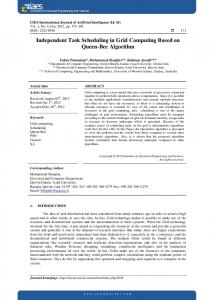
Input Data ri_x, ri_y, ri_z, rj_x, rj_y, rj_z, vi_x, vi_y, vi_z, vj_x, vj_y, vj_z, hi, hj, fi, fj, ci, cj, pi, pj, rhoi, rhoj, mj
#1 Difference Vector vij_x = vi_x – vj_x vij_y = vi_y – vj_y vij_z = vi_z – vj_z
#2 Difference Vector rij_x = ri_x – rj_x rij_y = ri_y – rj_y rij_z = ri_z – rj_z
#3 Mean Value hij = (hi + hj) / 2
#4 Mean Value fij = (fi + fj) / 2
#9 Scalarprod vrij = (vij_x × rij_x) + (vij_y × rij_y) + (vij_z × rij_z)
#5 Mean Value cij = (ci + cj) / 2
#10 Scalarprod rij2 = (rij_x × rij_x) + (rij_y × rij_y) + (rij_z × rij_z)
#12 muij muij = hij × vrij × fij / (rij2 + eta × hij × hij)
#13 Squareroot rij = sqrt rij2
#15 rh = rij × ihij
#6 Mean Value rhoij = (rhoi + rhoj) / 2
#7 p/rho2 prhoi2 = pi / (rhoi × rhoi)
#8 p/rho2 prhoj2 = pj / (rhoj × rhoj)
#11 ihij = 1 / hij
#14 ihij5 = ihij^5
#16 piij if vrij > 0 then piij = 0 else piij = (-alpha × cij × muij + beta × muij × muij) / rhoij
#17 Gradient of W if 0 < rh ≤ 1 then dW = (9 × rh / 4 - 3) × ihij5 else if 1 < rh ≤ 2 then dW = (-3 × rh /4 + 3 – 3 / rh) × ihij5 else dW = 0
#18 Scalar Factor dvs dvs = mj × (prhoi2 + prhoj2 + piij) × dW
#19 Build dv vector dv_x = dv_x + rij_x × dvs dv_y = dv_y + rij_y × dvs dv_z = dv_z + rij_z × dvs
Fig. 6.
Data flow graph of SPH pressure force calculation (with assigned node number in each box).
9|~r | |~ r | ij 3 0 < hij ≤1 ( 4h6ij − h5ij )(rix − rjx ) ij ∂i W 3|~ rij | |~ rij | 3 3 = (− 4h6 + h5 − h4 |~rij | )(rix − rjx ) 1 < hij ≤ 2 ij ij ij ∂x |~ rij | 0 hij > 2 (6) The diagram in Figure 6 shows the data flow to compute Equation 5, in which 19 nodes exist. In order to get desired performance and computation accuracy, fully pipelined double-precision (64-bit) floating point arithmetic units are needed to implement the graph in hardware. Many previous work have reported various floating-point arithmetic designs on FPGA devices [24], [25], [26], [27], [28], [29]. The resource utilization of pipelined double-precision (64-bit) floating-point operators based on literature survey is listed in Table II. Regarding the adder/subtractor (+/−) and multiplier (×), we select the results reported in [26], which are consistent
with the numbers reported in [29]. In terms of the divider (÷), the number reported in [27] is used since it is very close to the number reported in [26] and the reported operating frequency is above 200MHz, which is the frequency we are going to use for implementing the graph in Figure 6 on RCs. With respect √ to the square root operator ( ), the number reported in [28] is very close the number reported in [26]. We use the former since it targets Xilinx Virtex-II6000 device, which is used in one of target RC platforms, SRC-6 [30]. These primitive operators are used to construct the functionality of nodes in Figure 6. In general, multiple primitive operators are used to build a pipelined hardware node so that all operations in one FPGA configuration can be executed in parallel to maximize the throughput. For instance, node #12 needs 1 adder, 4 multipliers and 1 divider, which is denoted as “1A,4M,1D” in Table III, to implement so that it can operate in a pipelined fashion. The amount of slices occupied
TABLE II R ESOURCE UTILIZATION OF PIPELINED DOUBLE - PRECISION (64- BIT ) FLOATING - POINT OPERATORS .
Slices
+/− 1,640 [26]
× 2,085 [29]
÷ 4,173 [27]
√ 2,700 [28]
TABLE III R ESOURCE U TILIZATION OF N ODES ON T HREE D IFFERENT D EVICES Node No. 1 2 3 4 5 6 7 8 9 10 11 12 13 14 15 16 17 18 19 Overall a A:
Operatora Combination 3A 3A 1A 1A 1A 1A 1M,1D 1M,1D 2A,3M 2A,3M 1D 1A,4M,1D 1S 4M 1M 1A,4M,1D 3A,4M,1D 2A,2M 3A,3M 24A,30M,6D,1S
Slices 4,920 4,920 1,640 1,640 1,640 1,640 6,258 6,258 9,535 9,535 4,173 14,153 2,700 8,340 2,085 14,153 17,433 7,450 11,175 129,648
Percentage of Device Utilizationb V4LX200 V2-6000 V2P50 6.50 17.13 24.51 6.50 17.13 24.51 2.17 5.71 8.17 2.17 5.71 8.17 2.17 5.71 8.17 2.17 5.71 8.17 8.26 21.79 31.17 8.26 21.79 31.17 12.59 33.20 47.50 12.59 33.20 47.50 5.51 14.53 20.79 18.69 49.27 70.50 3.57 9.40 13.45 11.01 29.04 41.55 2.75 7.26 10.39 18.69 49.27 70.50 23.02 60.69 86.84 9.84 25.94 37.11 14.76 38.91 55.67 171.21 451.37 645.85
adder/subtractor, M: multiplier, D: divider, S: square root. 15% of slices in device are reserved for vendor service logic.
b Assume
by each node is simply the summation of the slices of the primitive operators. We list the percentage of slice utilization of each node on the FPGA devices of three representative reconfigurable computers in Table III, i.e., Xilinx Virtex4LX200 with SGI RC100, Virtex-II6000 with SRC-6 [30] and Virtex-IIP50 with Cray XD1 [31]. Apparently, multiple FPGA configurations are required to implement the dataflow graph in Figure 6 on all three platforms. We plan to simulate the SPH pressure force calculation dataflow graph on these three different platforms based on the slice utilization listed in Table III. Three different scheduling approaches, WBS, HPF-NF and RDMS will be applied on the graph, and their corresponding performance will be compared, analyzed and reported in future publications. V. C ONCLUSIONS Hardware/software co-design methodology is essential for the wide acceptance of RCs among domain scientists. The automatic co-design methodologies provide the ease of use and make the co-design feasible for large applications or complex system, however, suffer from lower performance when compared to manual co-design. This paper propose a Reduced
Data Movement Scheduling (RDMS) algorithm, which focuses on the optimization of the hardware execution task schedule. RDMS reduces the communication overhead as well as the hardware processing time using optimization techniques such as data dependency exploration resulting in fewer FPGA configurations. Simulation results show that the RDMS algorithm is able to produce 30% and 11% fewer configurations compared to the other proposed algorithms, WBS and HPF-NF. Furthermore, a proof-of-concept implementation of a complex 13-node task graph on a SGI RC100 reconfigurable computer shows that RDMS is able to reduce communication overhead by 48% and hardware processing time by 33% compared to WBS. This performance achievement on a complex example task graph demonstrates the potential of RDMS to improve the performance of complex real-world applications such as an astro-physics N-body simulation. ACKNOWLEDGMENT The authors would like to thank Guillermo Marcus from Institute for Computer Engineering of the University of Heidelberg in Germany for helpful discussions about N-body simulation using FPGAs. The authors also would like to acknowledge Gerhard Lienhart, Andreas Kugel and Reinhard M¨anner from University of Mannheim in Germany for providing the data flow graph of SPH pressure force calculation. R EFERENCES [1] E. El-Araby, M. Taher, M. Abouellail, T. El-Ghazawi, and G. Newby, “Comparative analysis of high level programming for reconfigurable computers: Methodology and empirical study,” in Proc. IEEE 3rd Southern Conference on Programmable Logic 2007 (SPL 2007), Feb. 2007, pp. 99–106. [2] P. Saha, E. El-Araby, M. Huang, M. Taher, S. Lopez-Buedo, T. ElGhazawi, C. Shu, K. Gaj, A. Michalski, and D. Buell, “Portable library development for reconfigurable computing systems: A case study,” Parallel Computing, vol. 34, no. 4+5, pp. 245–260, May 2008. [3] M. Wirthlin, D. Poznanovic, and et al., “OpenFPGA corelib core library interoperability effort,” in Proc. The 2007 Reconfigurable Systems Summer Institute (RSSI’07), July 2007. [4] OPENCORES – http://www.opencores.org. [5] S. P. Fekete, E. K¨ohler, and J. Teich, “Optimal FPGA module placement with temporal precedence constraints,” in Proc. Design, Automation and Test in Europe Conference and Exhibition, 2001 (DATE’01), Mar. 2001, pp. 658–665. [6] K. Bazargan, R. Kastner, and M. Sarrafzadeh, “Fast template placement for reconfigurable computing systems,” IEEE Design and Test of Computers, vol. 17, no. 1, pp. 68–83, Jan. 2000. [7] O. Diessel, H. ElGindy, M. Middendorf, H. Schmeck, and B. Schmidt, “Dynamic scheduling of tasks on partially reconfigurable fpgas,” IEE Proceedings - Computers and Digital Techniques, Special Issue on Reconfigurable Systems, vol. 147, no. 3, pp. 181–188, May 2000. [8] H. Walder and M. Platzner, “Non-preemptive multitasking on fpga: Task placement and footprint transform,” in Proc. the 2nd International Conference on Engineering of Reconfigurable Systems and Architectures (ERSA), June 2002, pp. 24–30. [9] G. Brebner and O. Diessel, “Chip-based reconfigurable task management,” in Proc. International Conference on Field Programmable Logic and Applications, 2001 (FPL 2001), Aug. 2001, pp. 182–191. [10] K. Compton, Z. Li, J. Cooley, S. Knol, and S. Hauck, “Configuration relocation and defragmentation for run-time reconfigurable computing,” IEEE Trans. VLSI Syst., vol. 10, no. 3, pp. 209–220, June 2002. [11] H. Walder, C. Steiger, and M. Platzner, “Fast online task placement on FPGAs: free space partitioning and 2D-hashing,” in Proc. IEEE International Parallel and Distributed Processing Symposium, 2003 (IPDPS’03), Apr. 2003, pp. 178–185.
[12] M. Handa and R. Vemuri, “A fast algorithm for finding maximal empty rectangles for dynamic FPGA placement,” in Proc. Design, Automation and Test in Europe Conference and Exhibition, 2004 (DATE’04), vol. 1, Feb. 2004, pp. 744–745. [13] K. Danne and M. Platzner, “A heuristic approach to schedule periodic real-time tasks on reconfigurable hardware,” in Proc. the 16th International Conference on Field Programmable Logic and Applications, 2005 (FPL 2005), Aug. 2005, pp. 568–573. [14] T. Wiangtong, P. Cheung, and W. Luk, “Multitasking in hardwaresoftware codesign for reconfigurable computer,” in Proc. the 2003 International Symposium on Circuits and Systems, (ISCAS ’03), vol. 5, May 2003, pp. 621–624. [15] P. Saha, “Automatic software hardware co-design for reconfigurable computing systems,” in Proc. International Conference on Field Programmable Logic and Applications, 2007 (FPL 2007), Aug. 2007, pp. 507–508. [16] Reconfigurable Application-Specific Computing User’s Guide (0074718-007), Silicon Graphics, Inc., Jan. 2008. ´ Tardos, Algorithm Design. [17] J. Kleinberg and E. Boston, MA: Pearson/Addison-Wesley, Mar. 2005. [18] G. Lienhart, A. Kugel, and R. M¨anner, “Using floating-point arithmetic on FPGAs to accelerate scientific N-body simulations,” in Proc. the 10th Annual IEEE Symposium on Field-Programmable Custom Computing Machines (FCCM’02), Apr. 2002, pp. 182–191. [19] L. B. Lucy, “A numerical approach to the testing of the fission hypothesis,” The Astronomical Journal, vol. 82, no. 12, pp. 1013–1024, Dec. 1977. [20] M. Sch¨ussler and D. Schmitt, “Comments on smoothed particle hydrodynamics,” Astronomy and Astrophysics, vol. 97, pp. 373–379, 1981. [21] J. J. Monaghan and J. C. Lattanzio, “A refined particle method for astrophysical problems.”
[22] L. Hernquist and N. Katz, “TreeSPH: a unification of SPH with the hierarchical tree method,” The Astrophysical Journal Supplement Series, vol. 70, pp. 419–446, June 1989. [23] J. J. Monaghan, “Smoothed particle hydrodynamics,” Annual Review of Astronomy and Astrophysics, vol. 30, pp. 543–574, 1992. [24] S. Paschalakis and P. Lee, “Double precision floating-point arithmetic on FPGAs,” in Proc. 2003 IEEE International Conference on FieldProgrammable Technology (FPT’03), Dec. 2003, pp. 352–358. [25] G. Govindu, L. Zhuo, S. Choi, and V. K. Prasanna, “Analysis of highperformance floating-point arithmetic on FPGAs,” in Proc. 18th International Parallel and Distributed Processing Symposium 2004 (IPDPS’04), Apr. 2004, pp. 149–156. [26] G. Govindu, R. Scrofano, and V. K. Prasanna, “A library of parameterizable floating-point cores for FPGAs and their application to scientific computing,” in Proc. The International Conference on Engineering Reconfigurable Systems and Algorithms (ERSA’05), June 2005, pp. 137– 145. [27] K. S. Hemmert and K. D. Underwood, “Open source high performance floating-point modules,” in Proc. the 14th Annual IEEE Symposium on Field-Programmable Custom Computing Machines (FCCM’06), Apr. 2006, pp. 349–350. [28] A. J. Thakkar and A. Ejnioui, “Design and implementation of double precision floating point division and square root on FPGAs,” in Proc. IEEE Aerospace 2006, Mar. 2006. [29] L. Zhuo and V. K. Prasanna, “Scalable and modular algorithms for floating-point matrix multiplication on reconfigurable computing systems,” IEEE Trans. Parallel Distrib. Syst., vol. 18, no. 4, pp. 433–448, Apr. 2007. [30] SRC CarteTM C Programming Environment v2.2 Guide (SRC-007-18), SRC Computers, Inc., Aug. 2006. [31] Cray XD1TM FPGA Development (S-6400-14), Cray Inc., May 2006.