Scheduling (RDMS) algorithm takes data dependency among tasks, hardware task .... a program into hardware tasks and software tasks and co- scheduled the ...... ence on Field Programmable Logic and Applications, 2007. (FPL 2007), Aug.
RDMS: A Hardware Task Scheduling Algorithm for Reconfigurable Computing Miaoqing Huang, Harald Simmler, Olivier Serres, and Tarek El-Ghazawi NSF Center for High-Performance Reconfigurable Computing (CHREC) Department of Electrical and Computer Engineering, The George Washington University {mqhuang,serres}@gwmail.gwu.edu, {simmler,tarek}@gwu.edu
Abstract Reconfigurable Computers (RC) can provide significant performance improvement for domain applications. However, wide acceptance of today’s RCs among domain scientist is hindered by the complexity of design tools and the required hardware design experience. Recent developments in HW/SW co-design methodologies for these systems provide the ease of use, but they are not comparable in performance to manual co-design. This paper aims at improving the overall performance of hardware tasks assigned to FPGA devices by minimizing both the communication overhead and configuration overhead, which are introduced by using FPGA devices. The proposed Reduced Data Movement Scheduling (RDMS) algorithm takes data dependency among tasks, hardware task resource utilization, and inter-task communication into account during the scheduling process and adopts a dynamic programming approach to reduce the communication between µP and FPGA co-processor and the number of FPGA configurations to a minimum. Compared to two other approaches that consider data dependency and hardware resource utilization only, RDMS algorithm can reduce inter-configuration communication time by 11% and 44% respectively based on simulation using randomly generated data flow graphs. The implementation of RDMS on a real-life application, N-body simulation, verifies the efficiency of RDMS algorithm against other approaches.
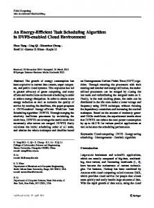
1. Introduction High-performance reconfigurable computers (HPRCs) are traditional HPCs extended with co-processors based on reconfigurable hardware like FPGAs. These enhanced systems are capable of providing significant performance improvement for scientific and engineering applications. Well known HPRC systems like the SGI RC100, the SRC-6, or the Cray XD1 use a high-speed interconnect, shown in Figure 1, to connect the general-purpose µP to the co-processor. Early attempts [1], [2], [3], [4], [5], [6], [7], [8] to improve the efficiency of FPGA co-processors used task placement algorithms in combination with partial run-time reconfiguration or dynamic reconfiguration to reduce the configuration This work was supported in part by the I/UCRC Program of the National Science Foundation under Grant No. IIP-0706352.
Host Memory
Microprocessor DMA
Interconnect
Vendor-Specific Service Logic
Local Memory Bank n-1
User Logic (IP)
Local Memory Bank 1
FPGA Device
Local Memory Bank 0
Figure 1. The General Architecture of A HighPerformance Reconfigurable Computer
overhead of the FPGA system. Most of these works map individual SW functions onto the FPGA to accelerate the whole application; however, the optimization strategies for task placement did not consider data communication or data dependencies among hardware tasks. We believe that an optimized hardware task scheduling algorithm has to take task dependencies, data communication, task resource utilization and system parameters into account to fully exploit the performance of an HPRC system. This paper presents an automated hardware task scheduling algorithm that is able to map simple and advanced data flow graphs (DFG) in an optimized way onto HPRC systems. More precisely, it is able to split a DFG onto multiple FPGA configurations optimizing the overall execution of the user application after the HW/SW partition has been done. The optimization is achieved by minimizing the amount of FPGA configurations and minimizing the inter-configuration communication overhead between the FPGA device and the µP using a data dependency analysis of the given DFG. Techniques like pipeline chaining of hardware tasks within the same FPGA configuration are used to improve the hardware processing concurrency. The described optimization is based on the facts that (1) we do not use partial reconfiguration, (2) we treat tasks in the DFG as black boxes, and (3) the DFG is directed and acyclic, i.e., a DAG. The remaining text is organized as follows. Section 2 introduces the related work. Section 3 presents the hardware task scheduling algorithm. Section 4 focuses on the implementation and results. Finally, Section 5 summaries this work.
2. Related Work Early work on hardware task placement for reconfigurable hardware focused on reducing configuration overhead and
therefore improving the efficiency of reconfigurable devices. In [1], an offline 3D module placement approach for partially reconfigurable devices was presented. Efficient data structures and algorithms for fast online task placements and simulation experiments for variants of first fit, best fit and bottom left bin-packing algorithms are presented in [2]. In [3], the fragmentation problem on partially reconfigurable FPGA devices was addressed. Task rearrangements were performed by techniques denoted as local repacking and ordered compaction. In [4], non-rectangular tasks were explored such that a given fragmentation metric was minimized. Furthermore, a task’s shape may be changed in order to facilitate task placement. In [5], a column-oriented one-dimensional task placement problem was discussed. Task relocations and transformations to reduce fragmentation were proposed in [6] based on a proposed FPGA architecture that supported efficient row-wise relocation. In [7], three improved partitioning algorithms based on [2] were presented. In [8], a fast algorithm for finding empty rectangles in partially reconfigurable FPGA device was presented. However, these algorithms only focused on utilizing the FPGA device efficiently through optimal task placement techniques and did not address the performance optimization among tasks in a given application, which is the main concern of the users of an HPRC system. More recently HW/SW co-design algorithms for RC systems emerged bringing the ease of use urgently needed in the RC domain. In [9], a HW/SW co-design model comprised of a single µP and an array of hardware processing elements (PEs implemented on FPGAs) was presented. Small tasks in a user program were dynamically assigned onto PEs. However, even if a single PE could accommodate multiple tasks, the tasks were executed in a sequential way. In [10], an automatic HW/SW co-design approach on RCs was proposed. The proposed ReCoS algorithm partitioned a program into hardware tasks and software tasks and coscheduled the tasks on their respective PEs. Although the ReCoS algorithm places multiple hardware tasks into the same configuration, each task is treated as a stand-alone hardware module. No data paths are defined between the tasks even if they reside in the same configuration.
3. Reduced Data Movement Scheduling Algorithm 3.1. Hardware Execution Model Executing an existing DFG on an FPGA device requires to configure the available array structure accordingly. Since the available resources in the FPGA device is limited, an existing DFG might have to be spread across multiple FPGA configurations. In addition to the necessary FPGA configuration time, input and output data have to be transferred between the FPGA device and the µP . This includes the
process cycle …...
FPGA Configuration
Data Communication
HW Data Processing
Data Communication
FPGA Configuration
…...
time
Figure 2. The Basic Execution Model of Hardware Tasks on FPGA Device data that have to be transferred between subsequent FPGA configurations as well. Figure 2 shows the basic execution model of hardware tasks running on an FPGA co-processor. After the device is configured and before hardware tasks start their computation, raw data are transferred from the µP to the FPGA device. After hardware tasks finish their computation, the processed data are transferred back from the FPGA device to the µP before the next FPGA configuration is loaded into the device∗ . In general, this sequence is defined as the process cycle containing three times: (1) FPGA configuration time, (2) hardware processing time, and (3) data communication time. FPGA configuration and data communication times are mostly system dependent and like on other co-processor approaches necessary for the operation. They are treated as pure overhead, because they have to be added to the hardware execution time and influence the overall co-processor system performance.
3.2. The Proposed Algorithm As mentioned earlier, configuration time and data communication time are pure overhead for using RCs and therefore they should be reduced to a minimum. Two strategies are applied to achieve this objective. (1) Execute as many tasks as possible in one FPGA configuration to minimize the amount of configurations. This will reduce the configuration overhead as well as the communication overhead between tasks. (2) Group communicating tasks into the same configuration to minimize the data communication time and to maximize the performance achieved through pipelining and concurrent task execution. In this section, we propose Reduced Data Movement Scheduling (RDMS) algorithm, a heuristic algorithm to produce a near-optimal scheduling solution with respect to minimum data communication and minimum amount of configurations. RDMS schedules the hardware tasks, given as a directed acyclic data flow graph, into a sequence of FPGA configurations† . ∗. In most cases the data communication and data processing are overlapped due to the high throughput of the hardware design. We intentionally distinguish these two times in this work for the sake of simplicity. †. Hardware processing time is not considered in the objective function since the communications and reconfigurable cost are greater than that time in most cases.
H0: imaginary root node 2
1
H1
1
H2 1
1 H5
1
H1
H3
2
2
3
3
H8
H9 1
4
Normalized node configuration time
2
Node Sequence No.
H5
H6
H7
4
3 H10
Node weight, i.e., normalized hardware resource utilization
H4
H7
2 2
H3
H4 2
H6
1
H2
H11
3
7
H12
H13
Normalized Communication Time
H8
H9
H10
H12
H11
H13
3
Figure 3. (a) An Example DFG Consisting of 13 Nodes; (b) Scheduling Result of the Example DFG Using RDMS
We identified the scheduling task as a dependent knapsack problem, which is a special case of the knapsack problem[11]. For the single-objective independent knapsack problem, there exists an exact solution that can be computed using a dynamic programming approach [12]. In the traditional knapsack problem, each object is associated with two parameters, the weight and the profit. The weight can be seen as a penalty that has to be paid for selecting an object and the profit is a reward. The goal of the knapsack problem is to maximize the profit subject to a maximum total weight. In our task scheduling case, we have a dependent knapsack problem where we have to take care of the task dependencies and make sure that all parent tasks have been scheduled before scheduling the corresponding child task so that internal data forwarding can become possible. The objects in the task scheduling knapsack problem are the hardware tasks given in the DFG. The weight of each object is the hardware resource utilization of the corresponding task. Because the objective of the knapsack problem is to maximize the profit, we have to define the profit according to our two goals: maximize the amount of tasks and maximize the inter-task communication in each configuration. Both profits are transformed into a common unit, time, so that it is able to summarize them into an overall profit that can be compared to other solutions. The amount of tasks is dependent on the allocated resources for each task. Therefore, we define one part of the profit to be the configuration time of each task. This configuration time is the fraction of the full configuration time of the FPGA device and it is proportional to the amount of used resources divided by the total available resource. This profit (task configuration time) is calculated for each task using Formula 1. task resource utilization × full FPGA configuration time (1) full resource of target FPGA device
The second part of the profit is defined as the time needed for the inter-task communication that is saved due to the fact that corresponding tasks are executed in the same configuration. This time (saved inter-task communication time) is computed by dividing two times inter-task communication data amount by the available I/O bandwidth between the µP and the FPGA device, also shown in Formula 2. We count the data amount twice because we save the time to transfer data out of the FPGA and back into the FPGA device again. The scheduling result of the example graph as illustrated in Figure 3(b) shows a saved inter-task communication time among task H2, H3, H6 and H10 of 12. inter-task communication volume × 2 I/O bandwidth between FPGA and µP
(2)
The example task graph in Figure 3(a) shows the resource utilization of each task normalized to 100 and the corresponding task configuration time calculated with respect to the full configuration time of 100 unitless time. The intertask communication time, shown next to the task graph edges, is also normalized to the full configuration time. 3.2.1. Mathematical Description of the Algorithm. The objective of the dependent knapsack problem is to find a subset of tasks that has a maximum combined task configuration time and a maximum saved inter-task communication time‡ . The dependent knapsack problem is described formally as follows. There are a DAG of n nodes of positive weight and one root node of no weight. The nodes in the DAG are numbered in an increasing order from top to bottom and from left to right at same level. Each node is associated with a profit, ci , 0 ≤ i ≤ n. Further, matrix E is to describe the ‡. The communication times between imaginary root node 0 and other nodes are not considered during the calculation since the corresponding data are input data to the whole graph and have to transferred anyway.
( POP T (i − 1, w) if wi > w POP T (i, w) = max(POP T (i − 1, w), POP T (i − 1, wj ) + ci + inter(i)) Otherwise S(i ( − 1, w) ) if wi > w S(i, w) = S(i − 1, w) if POP T (i − 1, w) > POP T (i − 1, wj ) + ci + inter(i) Otherwise {S(i − 1, w ), i} Otherwise j wj = max{x|x ≤ w − wi and all of node i’s parent nodes belong to S(i − 1, x)}; where ci is the configuration time of node i; inter(i) = P /* E(j,i) is the communication time between j and i */ j∈S(i−1,wj ),j6=0 E(j, i) × 2
Algorithm 1: Algorithm for Dependent Knapsack Problem Input: Array POP T [0..n, 0..W ], S[0..n, 0..W ] and a DAG of corresponding n nodes plus an imaginary root node 0. The nodes in the DAG are numbered in an increasing order from top to bottom and from left to right at the same level. Each node is associated with one weight wi and one profit ci . Matrix E[0..n, 0..n] describes the link among the nodes and the associated profit of each link in the DAG. Output: POP T [n, W ] is the optimal weight combination and S[n, W ] contains the corresponding nodes. 1.1 Initialize POP T [0, w] = S[0, w] = 0 for 0 ≤ w ≤ W , and POP T [i, 0] = S[i, 0] = 0 for 0 ≤ i ≤ n; 1.2 for i = 1 to n do 1.3 for w = 1 to W do 1.4 Use the recurrence (Equation 3) to compute POP T [i, w] and fill in S[i, w];
links among the nodes and E(i, j)§ is the profit associated with the edge between node i and j. It is required P to select a subset S ⊆ {1, . . . , n} of the nodes so that i∈S wi ≤ W (the P given upper bound) and, subject to two restrictions, (1) i∈S ci + interc(S), which is described in Equation 4, X interc(S) = E(i, j) × 2 (4) i,j∈S;i,j6=0
is as large as possible, and (2) all the parent nodes of any node i ∈ S belong to S as well. A dynamic programming algorithm, shown in Algorithm 1, is used to solve the dependent knapsack problem. POP T (i, w) denotes the value of the optimal solution over a subset of the items {1, . . . , i} with maximum allowed weight w. Similarly, S(i, w) is the corresponding subset. Equation 3 describes the recurrence among POP T (i, w)s and S(i, w)s. The RDMS algorithm, shown in Algorithm 2, applies Algorithm 1 on the DAG multiple times until all the nodes §. If there is no edge from i to j, E(i, j)=0.
(3)
Algorithm 2: RDMS Algorithm Input: A DAG of n + 1 nodes, representing n hardware tasks and an imaginary root node 0. Each node i has a weight wi and a profit ci . Matrix E[0..n, 0..n] describes the link among the nodes and the associated profit of each link in the DAG. Output: A sequencePof disjoint subsets {S1 , . . . , Sj } satisfying i∈Sk wi ≤ W , k = 1, . . . , j. 2.1 Let O denote the set of current remaining items and initialize O = {1, . . . , n}, let k=1; 2.2 while O is not empty do 2.3 Apply Algorithm 1 on O and DAG to find the subset Sk ; 2.4 Remove the items in the subset Sk from O and corresponding nodes from the DAG; 2.5 Connect those nodes whose parent nodes have been taken to the root node directly; 2.6 k = k + 1;
are scheduled. The scheduling result of the example graph using RDMS algorithm is shown in Figure 3(b), which consists of four FPGA configurations, {H2,H3,H6,H10}, {H1,H9,H12,H4,H7}, {H5,H8} and {H11,H13}. By taking two system parameters, the configuration time of hardware tasks and the inter-task communication time, into account, the RDMS algorithm can address the characteristics of different platforms automatically. On an RC system with a long configuration time, the configuration overhead of hardware tasks will play a more important role in the scheduling process. On a different RC system that can switch from one configuration to the other instantly, however, has a comparatively slow interconnect, the algorithm will favor to schedule two tasks having heavy communication in between into the same FPGA configuration.
4. Experimental Results In order to demonstrate the advantage of the proposed RDMS algorithm, we have compared it to two other solu-
L P R p R D M S R D M S
5 0
N u m b e r o f F P G A C o n fig u ra tio n s
In te r-c o n fig u ra tio n C o m m u n ic a tio n V o lu m e
6 0
L P R p R D M S R D M S
2 0 0 0
1 5 0 0
1 0 0 0
5 0 0
4 0
3 0
2 0
1 0
0 2 0
4 0
6 0
8 0
1 0 0
1 2 0
1 4 0
1 6 0
1 8 0
2 0 0
2 0
4 0
6 0
8 0
1 0 0
1 2 0
1 4 0
1 6 0
1 8 0
2 0 0
T a sk C o u n t (b )
T a sk C o u n t (a )
Figure 4. Scheduling Efficiency Comparison Among Three Approaches When Inter-task Communication Time Is Much Smaller Than Task Configuration Time: (a) Inter-configuration Communication, (b) Number of FPGA Configurations
tions that only consider hardware task resource utilization and data dependency. One algorithm is the previous version of RDMS algorithm, which was presented in [13] and termed as pRDMS thereafter. The other algorithm adopts a Linear Programming Relaxation [11] approach, termed as LPR thereafter. In the following part of this section, three different comparisons are made among the three algorithms. First, a direct comparison is carried out using the example graph in Figure 3(a). Second, randomly generated data flow graphs are used to cover a comprehensive scope of different applications. Third, a real-life application, an astrophysics N-body simulation, is emulated on SRC-6 and Cray XD1 platforms by applying RDMS and pRDMS algorithms.
4.1. Scheduling Comparison on Example Graph pRDMS algorithm is similar to RDMS algorithm; however, it does not consider the inter-task communication during the scheduling process. pRDMS algorithm schedules the 13 nodes of the example graph in Figure 3(a) also into four FPGA configuration, i.e., {H2,H3,H4,H6}, {H1,H7,H9,H10,H12},{H5,H8} and {H11,H13}. A direct comparison with result from RDMS shows that RDMS reduces the inter-configuration communication time by 21.1%. In the LPR approach to schedule hardware tasks represented by a DAG, it schedules the nodes level by level and does not consider the nodes in next level until all nodes in current level are scheduled. The typical LPR approach is to sort nodes in the same level into a decreasing order based on profit per weight ratio. Since the profit of each node is defined as configuration time and is linear to its weight, all nodes have the same profit per weight ratio in our case. Therefore, all nodes in the same level are sorted in a increasing order based on weight and then scheduled in a sequence. Once one FPGA configuration has no enough spare space to contain the node under consideration, it
Table 1. Scheduling Efficiency Improvement on Randomly Generated Graphs Using RDMS Against Other Two Algorithms
LPR pRDMS
Inter-configuration Communication Sim 1∗ Sim 2 Sim 3 49.1 % 39.7 % 42.7 % 13.0 % 7.0 % 13.1 %
Number of Configurations Sim 1 Sim 2 Sim 3 4.3 % 3.9 % 4.4 % 1.8 % 1.4 % 1.9 %
∗. Sim 1: Simulation 1; Sim 2: Simulation 2; Sim 3: Simulation 3.
starts a new configuration. LPR algorithm schedules the 13 nodes of the example graph into six FPGA configurations, i.e., {H2,H3,H4}, {H1,H6,H7}, {H5,H9,H10}, {H8}, {H11,H12}, {H13}. Correspondingly, RDMS reduces the inter-configuration communication time by 63.4% compared to LPR in this case.
4.2. Scheduling Comparison on Randomly Generated Synthetic Graphs In order to compare the scheduling efficiency among the three algorithms, i.e., LPR, pRDMS and RDMS, these algorithms have been implemented in C++. Randomly generated task graphs of node count from 20 to 200 were applied and the number of configurations and inter-configuration communication time were recorded. For each task graph, there are ten nodes in each level. Every node was randomly connected to one to three parent nodes; the weight and the configuration time of each node were the same and they were randomly assigned between 1 and 50. Three different simulations were carried out, representing three different types of systems. 1) Simulation 1: the inter-task communication time is randomly assigned between 1 and 10. In other words, the inter-task communication time is much smaller
Table 2. Resource Utilization of Pipelined Double-precision (64-bit) Floating-point Operators
Slices
+/− 1,640 [15]
× 2,085 [16]
÷ 4,173 [17]
√ 2,700 [18]
than task configuration time. This simulation represents those RC systems that have a long configuration time. 2) Simulation 2: the inter-task communication time is randomly assigned between 1 and 50. In other words, the inter-task communication time is comparably the same as the task configuration time. This simulation represents those RC systems that have a medium configuration time. 3) Simulation 3: the inter-task communication time is randomly assigned between 1 and 100. In other words, the inter-task communication time is much larger than the task configuration time. This simulation represents those RC systems that have a very short configuration time. By observing the scheduling results shown in Figure 4 and Table 1, RDMS algorithm is capable of reducing the interconfiguration communication time averagely by 11% and 44% compared to pRDMS and LPR algorithms respectively. In terms of number of FPGA configurations, RDMS algorithm generates in average 2% and 4% less configurations than pRDMS and LPR respectively.
4.3. Astrophysics N-Body Simulation 4.3.1. Application Description. The target application we intend to implement on reconfigurable computers is a part of the astrophysical N-Body simulations, in which the so called gas dynamical effects are simulated using a smoothed particle hydrodynamics (SPH) method [14]. In principle, this method uses gaseous matter represented as particles with position, velocity and a mass. A complex set of computations are carried out in order to obtain a continuous distribution of gas from these particles. The equation describing the SPH pressure force calculation used for our simulations is given in [13], with the corresponding task graph as shown in Figure 5 consisting of a total of 18 tasks. Elaboration of a few of the details of the graph relevant to our results will be presented along with the discussion of results later. In order to get desired performance and computation accuracy, fully pipelined double-precision (64-bit) floating point arithmetic units are needed to implement the graph in hardware. Many previous work have reported various floating-point arithmetic designs on FPGA devices. The resource utilization of pipelined double-precision (64-bit) floating-point operators based on literature survey is listed in Table 2. These primitive operators are used to construct the functionality of nodes in Figure 5. In general, multiple primitive
Table 3. Resource Utilization of Hardware Tasks Node No. 1,2 3,4,5,6 7 8,9 10 11,15 12 13 14 16 17 18 Overall
Operator∗ Combination 3A 1A 1M,1D 2A,3M 1D 1A,4M,1D 1S 4M 1M 3A,4M,1D 2A,2M 3A,3M 24A,29M,5D,1S
Slices 4,920 1,640 6,258 9,535 4,173 14,153 2,700 8,340 2,085 17,433 7,450 11,175 123,390
Percentage of Device Utilization† XC2V6000 XC2VP50 17.13 24.51 5.71 8.17 21.79 31.17 33.20 47.50 14.53 20.79 49.27 70.50 9.40 13.45 29.04 41.55 7.26 10.39 60.69 86.84 25.94 37.11 38.91 55.67 429.59 614.68
∗. A: adder/subtractor, M: multiplier, D: divider, S: square root. †. Assume 15% of slices in device are reserved for vendor service logic.
Table 4. Hardware Module Configuration Time and Inter-task Communication Time(unit: ms) Node No. 1,2 3 4 5 6 7 8,9 10 11 12 13 14 15 16 17 18
Configuration Time Inter-task SRC-6 Cray XD1 S. N.∗ D. N. 22.27 447.05 0 1 7.42 149.02 0 2 7.42 149.02 0 3 7.42 149.02 0 4 7.42 149.02 0 5 28.32 568.63 0 6 43.16 866.39 0 7 18.89 379.17 0 17 64.06 1286.00 1 8 12.22 245.33 2 18 37.75 757.80 2 8 9.44 189.45 2 9 64.06 1286.00 3 11 78.90 1584.03 3 10 33.72 676.94 4 11 50.58 1015.40 5 15
Communication Time Time S. N. D. N. Time 27.43 6 15 9.14 27.43 7 17 9.14 9.14 8 15 9.14 9.14 8 11 9.14 9.14 9 11 9.14 9.14 9 12 9.14 18.29 10 14 9.14 9.14 10 13 9.14 27.43 11 15 9.14 27.43 12 14 9.14 27.43 13 16 9.14 27.43 14 16 9.14 9.14 15 17 9.14 9.14 16 17 9.14 9.14 17 18 9.14 9.14
∗. S. N.: Source Node; D. N.: Destination Node
operators are used to build a pipelined hardware node so that all operations in one FPGA configuration can be executed in parallel to maximize the throughput. For instance, node #11 needs 1 adder, 4 multipliers and 1 divider, which is denoted as “1A,4M,1D” in Table 3, to implement so that it can operate in a pipelined fashion. The amount of slices occupied by each node is simply the summation of the slices of the primitive operators. We list the percentage of slice utilization of each node on the FPGA devices of two representative reconfigurable computers in Table 3, i.e., Virtex-II6000 with SRC-6 and Virtex-IIP50 with Cray XD1.
Input Data ri_x, ri_y, ri_z, rj_x, rj_y, rj_z, vi_x, vi_y, vi_z, vj_x, vj_y, vj_z, hi, hj, fi, fj, ci, cj, pi, pj, rhoi, rhoj, mj 24
24
#1 Difference Vector vij_x = vi_x – vj_x vij_y = vi_y – vj_y vij_z = vi_z – vj_z
8
#2 Difference Vector rij_x = ri_x – rj_x rij_y = ri_y – rj_y rij_z = ri_z – rj_z
8
#3 Mean Value hij = (hi + hj) / 2
#4 Mean Value fij = (fi + fj) / 2
24
24
8
24
8
8
8
8
#9 Scalarprod rij2 = (rij_x × rij_x) + (rij_y × rij_y) + (rij_z × rij_z)
8
#10 ihij = 1 / hij 8
8
8
#11 muij muij = hij × vrij × fij / (rij2 + eta × hij × hij)
#7 p/rho2 prhoi2 = pi / (rhoi × rhoi) or prhoj2 = pj / (rhoj × rhoj)
#6 Mean Value rhoij = (rhoi + rhoj) / 2
24
#8 Scalarprod vrij = (vij_x × rij_x) + (vij_y × rij_y) + (vij_z × rij_z)
16
8
8 #5 Mean Value cij = (ci + cj) / 2
#12 Squareroot rij = sqrt rij2
8
8
8
8
prhoi2
#13 ihij5 = ihij^5 8
8 Inter-task communication volume in byte for processing one neighbor particle
8
#14 rh = rij × ihij 8
#16 Gradient of W if 0 < rh ≤ 1 then dW = (9 × rh / 4 - 3) × ihij5 else if 1 < rh ≤ 2 then dW = (-3 × rh /4 + 3 – 3 / rh) × ihij5 else dW = 0
#15 piij if vrij > 0 then piij = 0 else piij = (-alpha × cij × muij + beta × muij × muij) / rhoij
8 8
8
#17 Scalar Factor dvs dvs = mj × (prhoi2 + prhoj2 + piij) × dW
#18 Build dv vector dv_x = dv_x + rij_x × dvs dv_y = dv_y + rij_y × dvs dv_z = dv_z + rij_z × dvs
Figure 5. Data Flow Graph of SPH Pressure Force Calculation (with assigned node number in each box) Table 5. SPH Pressure Force Scheduling Efficiency Comparison between pRDMS and RDMS
Inter-configuration Communication Time (s) Number of FPGA Configurations
SRC-6 Cray XD1 SRC-6 Cray XD1
pRDMS 0.347 0.512 5∗ 7‡
RDMS 0.329 0.384 5† 7§
∗. {1,2,6,7,8}, {3,4,5,9,10,13}, {11,15}, {12,14,16}, {17,18} †. {1,2,6,7,8}, {3,4,5,9,10,12,14}, {11,15}, {13,16}, {17,18} ‡. {1,2,3,4,7}, {8,9}, {6,11,12}, {5,10,13,14}, {16}, {15}, {17,18} §. {1,2,8}, {5,6,7,9}, {3,4,10,12,13}, {14,16}, {11}, {15}, {17,18}
Apparently, multiple FPGA configurations are required to implement the dataflow graph in Figure 5 on both platforms. 4.3.2. Testbeds. We emulated the SPH pressure force calculation pipeline on two different RC platforms, SRC-6 and Cray XD1, using RDMS algorithm. The whole FPGA configuration time is 130 ms on SRC-6 and 1,824 ms on Cray XD1 respectively. On both platforms, the sustained bandwidth of interconnect is 1.4×10⁹ B/s. In the implementation to emulate the SPH pressure force calculation, we assume all the calculations are carried out in double-precision (64-bit) format. As shown in Figure 5, the data of every particle consists of 13 scalar variables, i.e., 104 bytes. If we assume the number of particles to be emulated
is M and the number of neighbors of each particle is 100, then the original storage requirement is 104M bytes and the pipeline in Figure 5 needs to perform 100M iterations. 4.3.3. Result. In the emulation carried out on both SRC-6 and Cray XD1 systems, the number of particles is set at 16,000. Both pRDMS and RDMS algorithms are applied on the SPH graph based on the hardware task utilization, task configuration time and inter-task communication time listed in Table 3 and 4 for both platforms. The number of generated FPGA configurations and the inter-configuration communication time on both platforms are listed in Table 5. On SRC-6 platform, RDMS reduces the communication time by 5% compared to pRDMS. An analysis of both scheduling sequences has shown that pRDMS has eliminated some high volume data communication simply because they belong to the first tasks that were combined. For example, RDMS has scheduled task #9, #10, #12 and #14 into the same configuration whereas pRDMS has scheduled them into two separate configurations, which increases the overall inter-configuration communication. On Cray XD1, the communication reduction is increased to 25% since RDMS successfully schedules those tasks between which there exists heavy communications into the same configuration, e.g., #1, #2 and #8. The communication reduction is higher because Cray XD1 uses smaller FPGAs and therefore it is less likely that high volume communication transfers are
covered by pRDMS.
5. Conclusions This paper proposes a Reduced Data Movement Scheduling (RDMS) algorithm, which focuses on the optimization of the scheduling of tasks assigned to FPGA co-processors on RC systems. RDMS reduces the inter-configuration communication overhead and FPGA configuration overhead by taking data dependency, hardware task resource utilization and inter-task communication into account during scheduling process. Simulation results show that the RDMS algorithm is able to reduce inter-configuration communication time by 11% and 44% respectively and generate fewer FPGA configurations at the same time compared to pRDMS and LPR algorithms, which only consider data dependency and task resource utilization during scheduling. The implementation of a real-life application, N-body simulation, on both SRC6 and Cray XD1 platforms verifies the efficiency of RDMS algorithm against other approaches.
References [1] S. P. Fekete, E. K¨ohler, and J. Teich, “Optimal FPGA module placement with temporal precedence constraints,” in Proc. Design, Automation and Test in Europe Conference and Exhibition, 2001 (DATE’01), Mar. 2001, pp. 658–665. [2] K. Bazargan, R. Kastner, and M. Sarrafzadeh, “Fast template placement for reconfigurable computing systems,” IEEE Design and Test of Computers, vol. 17, no. 1, pp. 68–83, Jan. 2000. [3] O. Diessel, H. ElGindy, M. Middendorf, H. Schmeck, and B. Schmidt, “Dynamic scheduling of tasks on partially reconfigurable fpgas,” IEE Proceedings - Computers and Digital Techniques, Special Issue on Reconfigurable Systems, vol. 147, no. 3, pp. 181–188, May 2000. [4] H. Walder and M. Platzner, “Non-preemptive multitasking on fpga: Task placement and footprint transform,” in Proc. the 2nd International Conference on Engineering of Reconfigurable Systems and Architectures (ERSA), June 2002, pp. 24–30. [5] G. Brebner and O. Diessel, “Chip-based reconfigurable task management,” in Proc. International Conference on Field Programmable Logic and Applications, 2001 (FPL 2001), Aug. 2001, pp. 182–191. [6] K. Compton, Z. Li, J. Cooley, S. Knol, and S. Hauck, “Configuration relocation and defragmentation for run-time reconfigurable computing,” IEEE Trans. VLSI Syst., vol. 10, no. 3, pp. 209–220, June 2002. [7] H. Walder, C. Steiger, and M. Platzner, “Fast online task placement on FPGAs: free space partitioning and 2Dhashing,” in Proc. IEEE International Parallel and Distributed Processing Symposium, 2003 (IPDPS’03), Apr. 2003, pp. 178–185.
[8] M. Handa and R. Vemuri, “A fast algorithm for finding maximal empty rectangles for dynamic FPGA placement,” in Proc. Design, Automation and Test in Europe Conference and Exhibition, 2004 (DATE’04), vol. 1, Feb. 2004, pp. 744–745. [9] T. Wiangtong, P. Cheung, and W. Luk, “Multitasking in hardware-software codesign for reconfigurable computer,” in Proc. the 2003 International Symposium on Circuits and Systems, (ISCAS ’03), vol. 5, May 2003, pp. 621–624. [10] P. Saha, “Automatic software hardware co-design for reconfigurable computing systems,” in Proc. International Conference on Field Programmable Logic and Applications, 2007 (FPL 2007), Aug. 2007, pp. 507–508. [11] H. Kellerer, U. Pferschy, and D. Pisinger, Knapsack problems. Berlin; New York: Springer, 2004. ´ Tardos, Algorithm Design. Boston, MA: [12] J. Kleinberg and E. Pearson/Addison-Wesley, Mar. 2005. [13] M. Huang, H. Simmler, P. Saha, and T. El-Ghazawi, “Hardware task scheduling optimizations for reconfigurable computing,” in Proc. Second International Workshop on HighPerformance Reconfigurable Computing Technology and Applications (HPRCTA’08), Nov. 2008. [14] J. J. Monaghan and J. C. Lattanzio, “A refined particle method for astrophysical problems,” Astronomy and Astrophysics, vol. 149, pp. 135–143, 1985. [15] G. Govindu, R. Scrofano, and V. K. Prasanna, “A library of parameterizable floating-point cores for FPGAs and their application to scientific computing,” in Proc. The International Conference on Engineering Reconfigurable Systems and Algorithms (ERSA’05), June 2005, pp. 137–145. [16] L. Zhuo and V. K. Prasanna, “Scalable and modular algorithms for floating-point matrix multiplication on reconfigurable computing systems,” IEEE Trans. Parallel Distrib. Syst., vol. 18, no. 4, pp. 433–448, Apr. 2007. [17] K. S. Hemmert and K. D. Underwood, “Open source high performance floating-point modules,” in Proc. the 14th Annual IEEE Symposium on Field-Programmable Custom Computing Machines (FCCM’06), Apr. 2006, pp. 349–350. [18] A. J. Thakkar and A. Ejnioui, “Design and implementation of double precision floating point division and square root on FPGAs,” in Proc. IEEE Aerospace 2006, Mar. 2006.