Heterogeneous Concurrent Modeling and Design in Java (Volume 1 ...
Recommend Documents
Mar 15, 2001 - First, we design components to be domain polymorphic, meaning that they can ...... In Java, constructors are not inherited. ...... Occasionally, however, it is useful to create an applet that exercises more control over the display.
First, we design components to be domain polymorphic, meaning that they can interact with other ...... In Java, constructors are not inherited. Thus, in ..... They might be classical computer programs (applications), or any of a number of network- ..
Apr 15, 2008 - Department of Electrical Engineering and Computer Sciences. University of ..... The current time and current microstep of the model are advanced by the t Ï n,. (. ) = Ï n t t Ï1 n1. ,. (. ) Ï2 n2 ...... and Sensor Network Systems,â
Apr 1, 2008 - This work was supported in part by the Center for Hybrid and ... the U. S. Army Research Office (ARO #W911NF-07-2-0019), ...... We call the.
Apr 1, 2008 - lent, Bosch, HSBC, Lockheed-Martin, National Instruments, and Toyota. A ...... Visual syntaxes can be every bit as precise and complete as textual ...... objects, a specialized cross-reference list class, and a thread class .... actor.l
practical with computer control, e.g. to implement the nonlinear and time varying
... following cases from the theory and applications of control systems will ...
execution state set of state information needed to permit concurrent execution ...
The Threads class in Java is for concurrent programming not simulation.
Aimed primarily at undergraduate and graduate students in concurrent and distributed computing courses, Concurrent and Distributed Computing in Java by ...
ging a concurrent Java program is more di cult than a sequential ... 11 end;. 12 end if. 13 write(Total, sum);. 14 end. 1 begin. 2 read(X,Y);. 3 Total := 0.0;. 4. 5 if X
include data from legacy systems, database systems, data warehouses .... must adapt to the level of support required from stationary systems (servers). .... This means that the global history should be conflict free ... of the ticket. The main ...
trading volume and absolute change in mean earnings forecast. Varian (1985) ... of the absolute change in the consensus expectation on market volume. ..... trading volume on the day that a given interim earnings report appeared in the Wall.
Part I covers object-oriented programming in Java, graphical user interfaces and
... text Head First Java 2nd edition (HFJ) by Kathy Sierra and Bert Bates.
May 8, 2010 - Sangmin Park, Richard W. Vuduc, and Mary Jean Harrold. College ... E-mail: 1sangminp|richie|[email protected]. 245 ...... T. Anderson.
Programming in Java. Doug Lea. State University of New York at Oswego [email protected] http://gee.cs.oswego. ..... catch (InterruptedException e) { return; }.
JPF handles almost all pure Java code; exceptions include file input/output or network ... various modules communicate through Java RMI [11]. The version of ...
{liuxj, liuj, johane, eal}@eecs.berkeley.edu. Software-Enabled Control: Information Technology for Dynamical Systems. Tariq Samad and Gary Balas (eds.) ...
Design tools are needed that can support these heterogeneous models of ..... a zero-order hold, are implemented to convert between continuous-time signals and discrete events. A CT model is ..... products/whitepapers/powering.html) 2001.
paper proposes an innovative approach to design engineering ... Concurrent Engineering and Design course taught at .... Adobe Acrobat® format. Strong ...
paper suggests a simplified interference model for heterogeneous network. Leveraging ... as stochastic geometry [6]â[9] and often uses the Poisson .... We consider the power due to small-scale fading as oc- ..... the analysis and design of wireless
SIT-IN on Heterogeneous Data with Java, HTTP and Relations .... and extend a publicly available third party Java Applet, ESRI's MapCafè, provided with ...
Oct 1, 2012 - Knowledge Management in Public Administration: Brazil. Versus Portugal ... Elisabeth Brito, Leonor Pais, Lisete Mónico and. Liliana Jorge. 164.
[4] Toshiba Computer, Technical Specification Sheet for Tecra. 780DVD, 1998. [5] IBM Computer, Technical Specification Sheet for Thinkpad 600,. 770ED, 1998.
Dec 16, 2016 - Jingfeng Lu, National University of Singapore, Singapore. Jinpeng Ma, Rutgers University, USA. David Manl
Heterogeneous Concurrent Modeling and Design in Java (Volume 1 ...
Apr 1, 2008 - Heterogeneous Concurrent Modeling and Design in. Java (Volume 1: Introduction to Ptolemy II). Christopher Brooks. Edward A. Lee. Xiaojun ...
Heterogeneous Concurrent Modeling and Design in Java (Volume 1: Introduction to Ptolemy II)
Christopher Brooks Edward A. Lee Xiaojun Liu Stephen Neuendorffer Yang Zhao Haiyang Zheng
Electrical Engineering and Computer Sciences University of California at Berkeley Technical Report No. UCB/EECS-2008-28 http://www.eecs.berkeley.edu/Pubs/TechRpts/2008/EECS-2008-28.html
PTOLEMY II HETEROGENEOUS CONCURRENT MODELING AND DESIGN IN JAVA Edited by: Christopher Brooks, Edward A. Lee, Xiaojun Liu, Steve Neuendorffer, Yang Zhao, Haiyang Zheng
VOLUME 1: INTRODUCTION TO PTOLEMY II
T Y• O F•
SI
C
E
E BE
•
ER
I
H
T
NIV
E•U H
ORN
L IG H T
T
•T
Document Version 7.0 for use with Ptolemy II 7.0 April 1, 2008
LIF
A
A
R
A
Department of Electrical Engineering and Computer Sciences University of California, Berkeley http://ptolemy.eecs.berkeley.edu
LE
Authors: Shuvra S. Bhattacharyya Christopher Brooks Elaine Cheong John Davis, II Mudit Goel Bart Kienhuis Edward A. Lee Man-Kit Leung Jie Liu Xiaojun Liu Lukito Muliadi Steve Neuendorffer John Reekie Neil Smyth Jeff Tsay Brian Vogel Winthrop Williams Yuhong Xiong Yang Zhao Haiyang Zheng Gang Zhou
•1868•
Technical Report No. UCB/EECS-2007-7 Earlier versions: • UCB/EECS-2007-7, UCB/ERL M05/21, UCB/ERL M04/27, UCB/ERL M03/27, UCB/ERL M02/23, UCB/ERL M01/12, UCB/ERL M99/40 This work was supported in part by the Center for Hybrid and Embedded Software Systems (CHESS) at University of California, Berkeley, which receives support from the National Science Foundation (NSF awards #0720882 (CSR-EHS: PRET), #0647591 (CSR-SGER), and #0720841 (CSR-CPS)), the U. S. Army Research Office (ARO #W911NF-07-2-0019), the U. S. Air Force Office of Scientific Research (MURI #FA9550-06-0312), the Air Force Research Lab (AFRL), the State of California Micro Program, and the following companies: Agilent, Bosch, HSBC, Lockheed-Martin, National Instruments, and Toyota.
“Java” is a registered trademark of Sun Microsystems.
VOLUME 1 INTRODUCTION TO PTOLEMY II This volume describes how to construct Ptolemy II models for web-based modeling or building applications. The first chapter includes an overview of Ptolemy II software, and a brief description of each of the models of computation that have been implemented. It describes the package structure of the software, and includes as an appendix a brief tutorial on UML notation, which is used throughout the documentation to explain the structure of the software. The second chapter is a tutorial on building models using Vergil, a graphical user interface where models are built pictorially. The third chapter discusses the Ptolemy II expression language, which is used to set parameter values. The next chapter gives an overview of actor libraries. These three chapters, plus one of the domain chapters, will be sufficient for users to start building interesting models in the selected domain. The fifth chapter gives a tutorial on designing actors in Java. The sixth chapter describes the Ptolemy coding style, The seventh chapter explains MoML, the XML schema used by Vergil to store models. And the eighth chapter, the final one in this part, explains how to construct custom applets. Volume 2 describes the software architecture of Ptolemy II, and volume 3 describes the domains, each of which implements a model of computation.
This page intentionally left mostly blank.
Contents Volume 1 Introduction to Ptolemy II 4 Contents 7 1. Introduction 1 1.1. Purpose 1 1.1.1. Gabriel (1986-1991) 2 1.1.2. Ptolemy Classic (1990-1997) 2 1.1.3. Ptolemy II (1996-?) 2 1.1.4. Organization of this Document 4 1.2. Modeling and Design 4 1.2.1. Embedded Software 5 1.2.2. Actor-Oriented Design 6 1.2.3. Actor-Oriented Classes, Subclasses, and Inheritance 8 1.2.4. Syntaxes 10 1.2.5. Architecture Design 12 1.3. Models of Computation 14 1.3.1. Component Interaction - CI 15 1.3.2. Continuous Time - CT 15 1.3.3. Discrete-Events - DE 16 1.3.4. Distributed Discrete Events - DDE 16 1.3.5. Dynamic Data Flow - DDF 17 1.3.6. Discrete Time - DT 17 1.3.7. Finite-State Machines - FSM 17 1.3.8. Giotto 18 1.3.9. Graphics - GR 18 1.3.10. Heterochronous Dataflow 18 1.3.11. Hybrid Systems 18 1.3.12. Process Networks - PN 19 1.3.13. Rendezvous 22 1.3.14. Synchronous Dataflow - SDF 22 1.3.15. Synchronous/Reactive - SR 22 1.3.16. Timed Multitasking - TM 23 1.3.17. Wireless 23 1.4. Choosing Models of Computation 25 1.5. Ptolemy II Architecture 25 1.5.1. Core Packages 26 1.5.2. Overview of Key Classes 30 1.5.3. Domains 32 1.5.4. Library Packages 33
2. Using Vergil 47 2.1. Introduction 47 2.2. Quick Start 47 2.2.1. Starting Vergil 47 2.2.2. Executing a Pre-Built Model: A Signal Processing Example 49 2.2.3. Executing a Pre-Built Model: A Continuous-Time Example 50 2.2.4. Creating a New Model 54 2.2.5. Running the Model 55 2.2.6. Making Connections 56 2.3. Tokens and Data Types 58 2.4. Hierarchy 61 2.4.1. Creating a Composite Actor 61 2.4.2. Adding Ports to a Composite Actor 61 2.4.3. Setting the Types of Ports 63 2.5. Annotations and Parameterization 64 2.5.1. Parameters in Hierarchical Models 64 2.5.2. Decorative Elements 66 2.5.3. Creating Custom Icons 66 2.6. Navigating Larger Models 67 2.7. Classes and Inheritance 68 2.7.1. Creating and Using Actor-Oriented Classes 69 2.7.2. Overriding Parameter Values in Instances 71 2.7.3. Subclassing and Inheritance 72 2.7.4. Sharing Classes Across Models 73 2.8. Higher-Order Components 76 2.8.1. MultiInstance Composite 77 2.8.2. IterateOverArray 78 2.8.3. Mobile Code 79 2.8.4. Lifecycle Management Actors 79 2.9. Domains 80 2.9.1. SDF and Multirate Systems 81 2.9.2. Data-Dependent Rates 82 2.9.3. Discrete-Event Systems 83 2.9.4. Wireless and Sensor Network Systems 86 2.9.5. Continuous-Time Systems 86
2.10.Hybrid Systems and Modal Models 86 2.10.1. Examining a Pre-Built Model 86 2.10.2. Numerical Precision and Zeno Conditions 89 2.10.3. Constructing Modal Models 90 2.10.4. Execution Semantics 93 2.11.Using the Plotter 93
3. Expressions 97 3.1. Introduction 97 3.1.1. Expression Evaluator 97 3.2. Simple Arithmetic Expressions 98 3.2.1. Constants and Literals 98 3.2.2. Variables 100 3.2.3. Operators 100 3.2.4. Comments 102 3.3. Uses of Expressions 102 3.3.1. Parameters 102 3.3.2. Port Parameters 103 3.3.3. String Parameters 104 3.3.4. Expression Actor 104 3.3.5. State Machines 105 3.4. Composite Data Types 106 3.4.1. Arrays 106 3.4.2. Matrices 109 3.4.3. Records 111 3.5. Invoking Methods 113 3.6. Defining Functions 114 3.7. Built-In Functions 116 3.8. Nil Tokens 120 3.9. Fixed Point Numbers 121 3.10.Units 122 Trigonometric Functions 125 Basic Mathematical Functions 127 Matrix, Array, and Record Functions. 129 Functions for Evaluating Expressions 130 Signal Processing Functions 132 I/O Functions and Other Miscellaneous Functions 134
4. Actor Libraries 137 4.1. Overview 137 4.2. Actor Classes 138 4.3. Data Polymorphism 140 4.4. Domain Polymorphism 140 4.5. Actor Summaries 141 4.5.1. Sources 142 4.5.2. Sinks 144 4.5.3. Array 147 4.5.4. Conversions 147 4.5.5. Flow Control 149
Higher Order Actors 151 I/O 153 Logic 153 Math 154 Matrix 155 Random 155 Real Time 156 Signal Processing 156 String 159 Domain Specific 160
5. Designing Actors 167 5.1. Overview 167 5.2. Anatomy of an Actor 168 5.2.1. Ports 168 5.2.2. Port Rates and Dependencies Between Ports 173 5.2.3. Parameters 175 5.2.4. Constructors 176 5.2.5. Cloning 177 5.3. Action Methods 178 5.3.1. Initialization 179 5.3.2. Prefire 179 5.3.3. Fire 181 5.3.4. Postfire 183 5.3.5. Wrapup 183 5.4. Coupled Port and Parameter 185 5.5. Iterate Method 187 5.6. Time 188 5.7. Icons 188 5.7.1. The Older Method 188 Appendix: Creating and Using a Simple Actor 190
6. Coding Style 193 6.1. Motivation 193 6.2. Anatomy of a File 194 6.2.1. Copyright 194 6.2.2. Imports 197 6.3. Comment Structure 198 6.3.1. Javadoc and HTML 198 6.3.2. Class documentation 198 6.3.3. Code rating 199 6.3.4. Constructor documentation 200 6.3.5. Method documentation 200 6.3.6. Referring to methods in comments 202 6.3.7. Tags in method documents 203 6.3.8. FIXME annotations 203 6.4. Code Structure 203 6.4.1. Names of classes and variables 203 6.4.2. Indentation and brackets 204
6.4.3. Spaces 204 6.4.4. Exceptions 205 6.4.5. Code Cleaning 205 6.5. Directory naming conventions 206 6.6. Checklist for new files 206 6.6.1. File Structure 206 6.6.2. Class comment 206 6.6.3. Constructor, method, field and inner class Javadoc documentation. 206 6.6.4. Overall 206
7. MoML 209 7.1. Introduction 209 7.2. MoML Principles 211 7.2.1. Clustered Graphs 212 7.2.2. Relation Groups 213 7.2.3. Abstraction 213 7.3. Specification of a Model 214 7.3.1. Data Organization 214 7.3.2. Overview of XML 216 7.3.3. Names and Classes 217 7.3.4. Top-Level Entities 218 7.3.5. Entity Element 218 7.3.6. Properties 219 7.3.7. Doc Element 221 7.3.8. Ports 222 7.3.9. Relations and Links 224 7.3.10. Classes 226 7.3.11. Inheritance 229 7.3.12. Directors 229 7.3.13. Input Element 230 7.3.14. Annotations for Visual Rendering 230 7.4. Incremental Parsing 231 7.4.1. Adding Entities 231 7.4.2. Using Absolute Names 232 7.4.3. Adding Ports, Relations, and Links 232 7.4.4. Changing Port Configurations 232 7.4.5. Deleting Entities, Relations, and Ports 233 7.4.6. Renaming Objects 233 7.4.7. Converting a Class to an Entity or Vice Versa 234 7.4.8. Changing Documentation, Properties, and Directors 234 7.4.9. Removing Links 235 7.4.10. Grouping Elements 236 7.5. Parsing MoML 237 7.6. Exporting MoML 238 7.7. Special Attributes 240 7.8. Acknowledgements 240 Appendix: Example 241 Sinewave Generator 241
Modulation 245
8. Custom Applets 251 8.1. Introduction 251 8.2. HTML Files Containing Applets 252 8.3. Defining a Model in a Java File 253 8.3.1. A Model Class as a Composite Actor 253 8.3.2. Compiling 255 8.3.3. Executing the Model in an Application 257 8.3.4. Extending PtolemyApplet 258 8.3.5. Using Model Parameters 258 8.3.6. Adding Custom Actors 259 8.3.7. Using Jar Files 261 8.3.8. Hints for Developing Applets 262
References 263 Glossary 275 Index 279
Introduction Author: Contributors:
Edward A. Lee The entire Ptolemy team
1.1 Purpose This document is the first of three volumes describing the Ptolemy II software. This first volume introduces the software and explains how to use it. The second volume documents the software architecture and explains how to extend it. The third volume documents the “domains,” which realize models of computation. Some of these are relatively mature and established, while some are highly experimental. Indeed, a major part of the Ptolemy Project is experimentation with models of computation (MoCs). Ptolemy II is the current software infrastructure of the Ptolemy Project. For the participants in the Ptolemy Project, Ptolemy II is first and foremost a laboratory for experimenting with design techniques. It is published freely and in open-source form for several reasons. First, the software complements more traditional publication media, and serves as a clear, unambiguous, and complete description of our research results. Second, the open architecture and open source encourages researchers to build their own methods, leveraging and extending the core infrastructure provided by the software. This creates a community where much of the dialog is through the software. Third, the freely available software encourages designers to try out the new design techniques that are introduced and give feedback to the Ptolemy Project. This helps guide further research. Fourth, the open source software encourages commercial providers of software tools to commercialize the research results, which helps to maximize the impact of the work. The Ptolemy Project is an informal group of researchers at University of California, Berkeley. There have been many participants in the project over the years (see “Acknowledgements” on page 40 for a list of contributors to Ptolemy II). Ptolemy II is the third generation of design software to emerge from this group, with each generation addressing a new set of problems, with new emphasis, and (largely) a new group of contributors.
Heterogeneous Concurrent Modeling and Design
1
Introduction
1.1.1 Gabriel (1986-1991) The first generation of software created by this group was called Gabriel [19]. It was written in Lisp and aimed at signal processing. It was during the construction of Gabriel that the synchronous dataflow (SDF) MoC and both sequential and parallel scheduling techniques for SDF models matured. Gabriel included code generators for programmable DSPs that produced efficient assembly code for certain processors (notably, Motorola processors). Gabriel included hardware/software co-simulators, where parallel code generators would produce assembly code which then ran on instruction set simulators within a hardware simulation of a multiprocessor architecture. Gabriel had a graphical user interface built on top of Vem, written by Rick Spickelmeyer, which was originally designed for schematic capture in VLSI CAD. It used Oct, which was the design database developed by the Berkeley CAD group under the leadership of Professor Richard Newton.
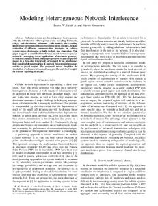
1.1.2 Ptolemy Classic (1990-1997) Ptolemy Classic, started jointly by Professors Edward Lee and Dave Messerschmitt in 1990, was written in C++ [23]. It was the first modeling environment to systematically support multiple models of computation, hierarchically combined. We ported the SDF capabilities from Gabriel, and also developed boolean dataflow (BDF), dynamic dataflow (DDF), multidimensional synchronous dataflow (MDSDF) and process networks (PN) domains. We also ported the DSP code generators, and created C and VHDL code generators as well. We developed the concept of “targets,” which encapsulated knowledge about specific hardware platforms, and demonstrated construction of models that executed on attached embedded processors (such as S-bus cards with DSPs), including models that executed jointly on a Unix host and the attached embedded processor. We developed a discrete-event domain and demonstrated joint modeling of communication networks and signal processing, and also developed a hardware simulation domain called Thor, which was adapted from an open-source hardware simulator by the same name (see figure 1.1). We made major contributions to SDF scheduling techniques, including introducing the concept of “single appearance schedules” (which minimize generated code size and enable extensive use of inlining of generated code). We also introduced “higherorder components,” which greatly increased the expressiveness of visual syntaxes. The Ptolemy Classic user interface was an extension of the Gabriel interface, still based on Oct and Vem, but extended by Tycho (written in Itcl, an object-oriented extension of Tcl/Tk). Portions of Ptolemy Classic were commercialized as part of the Agilent ADS system, and methods from Ptolemy Classic were used in Cadence’s SPW system.
1.1.3 Ptolemy II (1996-?) The Ptolemy Project (as it was now known) began working on Ptolemy II in 1996. One reason for starting over was to exploit the network integration, code migration, built-in threading, and user-interface capabilities of Java. Ptolemy II introduced the notion of domain polymorphism (where components could be designed to be able to operate in multiple domains) and modal models (where finite state machines are combined hierarchically with other models of computation). We built a continuoustime domain, that when combined with the modal modeling capability, yields hybrid system modeling. Ptolemy II has a sophisticated type system with type inference and data polymorphism (where components can be designed to operate on multiple data types), and a rich functional expression language. The concept of behavioral types emerged (where components and domains could have interface definitions that describe not just static structure, as with traditional type systems, but also dynamic behavior). Some (but not all) of the SDF capabilities from Ptolemy Classic were ported, and the
2
Ptolemy II
Introduction
heterochronous dataflow model was introduced. We contributed to a user-interface toolkit (called Diva) based on Java, built a user interface for Ptolemy II (called Vergil) based on Diva, designed a Java plotter (PtPlot), and introduced a 3-D animation domain. We built models that could be used as applets in a web browser. We introduced actor-oriented classes and subclasses with inheritance, and we added modeling capabilities for wireless systems. We also introduced lifecycle management actors and dynamically evaluated higher-order components. And we built numerous experimental domains that explored real-time and distributed computing (distributed discrete events (DDE), timed multitasking (TM), Giotto, and component interaction (CI)). As for code generation, the tactic in Ptolemy II embodies two approaches, both significantly different than that in Gabriel or Ptolemy Classic. In the first approach, instead of components as generators, the code generator called Copernicus uses a component-specialization framework built on top of a Java compiler toolkit called Soot. The second approach has components as generators, but uses an architecture where the interfaces of components are defined exactly as in ordinary Ptolemy II actors,
FIGURE 1.1. Ptolemy Classic screen image (from 1993) showing an SDF graph at the upper left that is automatically mapped and scheduled onto the two processor architecture, whose model is at the lower right (in the “Thor” domain). Assembly code for the two processors is generated, and then ISA simulators of the processors (provided by Motorola, lower left) interact with the Thor-domain simulation, resulting in the logic analyzer trace at the upper right.
Heterogeneous Concurrent Modeling and Design
3
Introduction
and “helpers” are used to generate code for particular targets. Also new to Ptolemy II is the use of XML for its persistent data representation. It has also introduced the concept of migrating models. It further provides an infrastructure for creating specialized “configurations,” which are packaged subsets of the Ptolemy II software together with customized documentation and interfaces. HyVisual, VisualSense, and Kepler are examples of separate software applications that are built as Ptolemy II configurations.
1.1.4 Organization of this Document This document is the first of three volumes. This first volume introduces the software and explains how to use it. It begins with a description of the rationale for the design in this chapter. The second chapter is a tutorial that explains how to use Ptolemy II via the Vergil visual editor. The third chapter explains the functional expression language, which is used extensively in Ptolemy II. The fourth chapter provides an overview of the actor libraries; note, however, that the most complete documentation for the actors is built in to the software, accessed through the “Get Documentation” command, obtained in Vergil by right clicking on the actor icon. The fifth chapter explains how to write actors. The sixth chapter describes MoML, the XML schema used to store Ptolemy II models. A great deal more information, including many published papers, can be found on the Ptolemy Project website, http://ptolemy.org. In addition, extensive documentation is available on-line when running Vergil. Right clicking on most objects will offer a “Get Documentation” choice.
1.2 Modeling and Design The Ptolemy project studies heterogeneous modeling, simulation, and design of concurrent systems. A major focus is on embedded systems [84], particularly those that mix technologies including, for example, analog and digital electronics, hardware and software, and electronics and mechanical devices. Another major focus is on systems that are complex in the sense that they mix widely different operations, such as networking, signal processing, feedback control, mode changes, sequential decision making, and user interfaces. Modeling is the act of representing a system or subsystem formally. A model might be mathematical, in which case it can be viewed as a set of assertions about properties of the system such as its functionality or physical dimensions. A model can also be constructive, in which case it defines a computational procedure that mimics a set of properties of the system. Constructive models are often used to describe behavior of a system in response to stimulus from outside the system. Constructive models are also called executable models. Design is the act of defining a system or subsystem. Usually this involves defining one or more models of the system and refining the models until the desired functionality is obtained within a set of constraints. Design and modeling are obviously closely coupled. In some circumstances, models may be immutable, in the sense that they describe subsystems, constraints, or behaviors that are externally imposed on a design. For instance, they may describe a mechanical system that is not under design, but must be controlled by an electronic system that is under design. Executable models are sometimes called simulations, an appropriate term when the executable model is clearly distinct from the system it models. However, in many electronic systems, a model that starts as a simulation mutates into a software implementation of the system. The distinction between the model and the system itself becomes blurred in this case. This is particularly true for embedded
4
Ptolemy II
Introduction
software.
1.2.1 Embedded Software Embedded software is software that resides in devices that are not first-and-foremost computers. It is pervasive, appearing in automobiles, telephones, pagers, consumer electronics, toys, aircraft, trains, security systems, weapons systems, printers, modems, copiers, thermostats, manufacturing systems, appliances, etc. A technically active person probably interacts regularly with more pieces of embedded software than conventional software. A key feature of embedded software is that it engages the physical world, and hence has temporal constraints that desktop software does not share. A major emphasis in Ptolemy II is on the methodology for defining and producing embedded software together with the systems within which it is embedded. Executable models are constructed under a model of computation, which is the set of “laws of physics” that govern the interaction of components in the model. If the model is describing a mechanical system, then the model of computation may literally be the laws of physics. More commonly, however, it is a set of rules that are more abstract, and provide a framework within which a designer builds models. A set of rules that govern the interaction of components is called the semantics of the model of computation. A model of computation may have more than one semantics, in that there might be distinct sets of rules that impose identical constraints on behavior. The choice of model of computation depends strongly on the type of model being constructed. For example, for a purely computational system that transforms a finite body of data into another finite body of data, the imperative semantics that is common in programming languages such as C, C++, Java, and MATLAB will be adequate. For modeling a mechanical system, the semantics needs to be able to handle concurrency and the time continuum, in which case a continuous-time model of computation such as that found in Simulink, Saber, Agilent’s ADS, and VHDL-AMS is more appropriate. The ability of a model to mutate into an implementation depends heavily on the model of computation that is used. Some models of computation, for example, are suitable for implementation only in customized hardware, while others are poorly matched to customized hardware because of their intrinsically sequential nature. Choosing an inappropriate model of computation may compromise the quality of design by leading the designer into a more costly or less reliable implementation. A principle of the Ptolemy project is that the choices of models of computation strongly affect the quality of a system design. For embedded systems, the most useful models of computation handle concurrency and time. This is because embedded systems consist typically of components that operate simultaneously and have multiple simultaneous sources of stimuli. In addition, they operate in a timed (real world) environment, where the timeliness of their response to stimuli may be as important as the correctness of the response. The objective in Ptolemy II is to support the construction and interoperability of executable models that are built under a wide variety of models of computation. Ptolemy II takes a component view of design, in that models are constructed as a set of interacting components. A model of computation governs the semantics of the interaction, and thus imposes a discipline on the interaction of components.
Heterogeneous Concurrent Modeling and Design
5
Introduction
Component-based design in Ptolemy II involves disciplined interactions between components governed by a model of computation.
1.2.2 Actor-Oriented Design Most (but not all) models of computation in Ptolemy II support actor-oriented design. This contrasts with (and complements) object-oriented design by emphasizing concurrency and communication between components. Components called actors execute and communicate with other actors in a model, as illustrated in figure 1.2. Like objects, actors have a well defined component interface. This interface abstracts the internal state and behavior of an actor, and restricts how an actor interacts with its environment. The interface includes ports that represent points of communication for an actor, and parameters that are used to configure the operation of an actor. Often, parameter values are part of the a priori configuration of an actor and do not change when a model is executed, but not always. The “port/parameters” shown in figure 1.2 function as both ports and parameters. Central to actor-oriented design are the communication channels that pass data from one port to another according to some messaging scheme. Whereas with object-oriented design, components interact primarily by transferring control through method calls, in actor-oriented design, they interact by sending messages through channels. The use of channels to mediate communication implies that actors interact only with the channels that they are connected to and not directly with other actors. Like actors, a model may also define an external interface; this interface is called its hierarchical abstraction. This interface consists of external ports and external parameters, which are distinct from the ports and parameters of the individual actors in the model. The external ports of a model can be connected by channels to other external ports of the model or to the ports of actors that compose the model. External parameters of a model can be used to determine the values of the parameters of actors annotation director
port/parameters link to documentation actor port
external port relation model
hierarchical abstraction
FIGURE 1.2. Illustration of an actor-oriented model (above) and its hierarchical abstraction (below).
6
Ptolemy II
Introduction
inside the model. Taken together, the concepts of models, actors, ports, parameters and channels describe the abstract syntax of actor-oriented design. The abstract syntax gives the structure of models without saying anything about how they operate. This syntax can be represented concretely in several ways, such as graphically, as in figure 4, in XML as in figure 1.3, or in a program designed to a specific API (as in SystemC). Ptolemy II offers all three alternatives. It is important to realize that the syntactic structure of an actor-oriented design says little about the semantics. The semantics is largely orthogonal to the syntax, and is determined by a model of computation. The model of computation might give operational rules for executing a model. These rules determine when actors perform internal computation, update their internal state, and perform external communication. The model of computation also defines the nature of communication between components. Our notion of actor-oriented modeling is related to the work of Gul Agha and others. The term actor was introduced in the 1970’s by Carl Hewitt of MIT to describe the concept of autonomous reasoning agents [59]. The term evolved through the work of Agha and others to describe a formalized model of concurrency [1-5]. Agha’s actors each have an independent thread of control and communicate via asynchronous message passing. We have further developed the term to embrace a larger family of models of concurrency that are often more constrained than general message passing. Our actors are still conceptually concurrent, but unlike Agha’s actors, they need not have their own thread of control. Moreover, although communication is still through some form of message passing, it need not be strictly asynchronous. Actor-oriented modeling has been around for some time, and is in widespread use through such programs as Simulink, from The Mathworks, LabVIEW, from National Instruments, and many others. It is gaining broader legitimacy through the efforts of OMG in UML-2 [123], for example, some of which has its roots in the actor-oriented framework ROOM [139]. Many research projects are based on some form of actor-oriented modeling, but the Ptolemy Project is unique in the breadth of exploration of semantic alternatives and in the commitment made to a particular model of computation within a domain. Because domains can be mixed hierarchically, each domain can be made more specialized
FIGURE 1.3. An XML representation of a simplified sinewave source.
Heterogeneous Concurrent Modeling and Design
7
Introduction
without compromising its utility. Perhaps the earliest actor-oriented programming language was created by William (Bert) Sutherland on a TX-2 computer at MIT Lincoln Labs [142]. Sutherland’s system had a visual syntax, where a programmer would use a light pen to create diagrams representing programs. His system was built on top one of the first acknowledged object-oriented programming systems, Sketchpad, created by his brother Ivan Sutherland [141].
1.2.3 Actor-Oriented Classes, Subclasses, and Inheritance Starting with version 4.0 of Ptolemy II, we have extended actor-oriented design techniques with modularity mechanisms analogous to those found in object-oriented languages [79]. Consider a simple example, shown in figure 1.4. The model at the lower left is the same sine wave generator as in figure 1.2. In figure 1.2, the block labeled “Sinewave” at the bottom actually represents an instance of a class, local class definition
execution result
instance inherited actors instance
subclass override actors
top-level class definition
FIGURE 1.4. Illustration of actor-oriented classes, subclasses, and inheritance.
8
Ptolemy II
Introduction
where the definition of the class is given by the block diagram at the top of figure 1.2. In figure 1.4, that class definition is extended to create a new subclass definition called “NoisySinewave,” whose definition is shown at the bottom right of the figure. That subclass “inherits” components (actors) and connections from the base class. The inherited components are outlined with a dashed outline. It then overrides the definition by adding a second output port, two more override actors and connections between these. These additions have no dashed outline. The NoisySinewave class definition is local to the model at the upper left of figure 1.4. That is, the class definition is part of the model definition and is available for instantiation and subclassing only within this model. The class definition is shown visually by an icon that is outlined in light blue to distinguish it visually from an instance. This contrasts with the Sinewave class definition, which is defined in its own model file, and is accessible to any model that wishes to use it. Thus, Ptolemy II provides levels of visibility and well-defined scoping for class definitions. Moreover, class definitions can themselves contain class definitions, so Ptolemy II provides “inner classes” of a sort. A class that is defined in its own file is called a top-level class. Any model can instantiate or subclass a top-level class if the file defining the class is in the classpath. A class that is a component in a model and is available for instantiation or subclassing is called a local class. The Sinewave class in figure 1.4 is a top-level class, while NoisySinewave is a local class. When a class is defined within a model, its definition is in scope at the same level of the hierarchy where it is defined and at all levels below that1. Thus, for example, the model at the upper left in figure 1.4 contains both the class definition NoisySinewave and the instance InstanceOfNoisySinewave. The model in figure 1.4, when executed, produces two signal traces, as shown in the plot at the upper right. One is a simple sine wave and the other is a noisy sine wave. The simple sine wave is generated by the Sinewave actor, which is an instance of the Sinewave class (defined in a separate file), and the noisy sine wave is generated by the InstanceOfNoisySinewave actor, which is an instance of NoisySinewave, a subclass of Sinewave. In building this mechanism into Ptolemy II, we had to make a number of decisions that amount to language design decisions. First, in Ptolemy II, a model is a set of actors, ports, attributes, and connections. A model can be viewed as a program with (optionally) a visual syntax. Each of the three gray boxes containing actors, connections, and annotations in figure 1.4 is a model. In Ptolemy II, any model can be either a class or an instance. A class serves as a prototype for instances. Our mechanism, therefore, is closely related to prototype-based languages (see chapter 3 of [32], for example), but with a twist. In order to ensure that the class mechanism operates entirely at the abstract syntax level, classes in Ptolemy II are purely syntactic objects and play no role in the execution of a model. They are not visible to the director, which provides the execution engine. As consequence, Ptolemy II does not permit the ports of a class definition to be connected to other ports, and any attempt to connect the box labeled NoisySinewave in figure 1.4 will trigger an error. A subclass inherits the structure of its base class. Specifically, every object (actor, attribute, port or connection) contained by the base class has a corresponding object in the subclass. We refer to this as the derivation invariant. The pink dashed outlines in figure 1.4 surround such “corresponding objects.” They provide a visual indication that those objects cannot be removed, since doing so would violate the derivation invariant. However, the subclass can contain new objects and can also change (override) the values of attributes that carry values (we generally refer to attributes that carry values as parame1. This is the same scoping rule that applies to attributes in the Ptolemy II expression language, described in a subsequent chapter.
Heterogeneous Concurrent Modeling and Design
9
Introduction
ters). Since a model can contain class definitions, and a model can itself be a class definition, we have inner classes. This is a significant departure from the prototype mechanism given in [68], where it is (correctly) pointed out that such inner classes create significant complications. In particular, they create a specialized form of multiple inheritance. Although this is a significant complication, we believe that it is sufficiently disciplined, modular, and expressive to be justified. The underlying formalism is given in [79]. A number of related experiments in this direction have also been performed by others. The GME system from Vanderbilt [69] has been extended to support actor-oriented prototypes [68]. Some older projects also extend actor-oriented models with modularity methods. CodeSign [40] from ETH builds in an object-oriented notion of classes into a design environment based on time Petri nets. Concurrent ML [131], with its synchronous message passing between threads, built in a functional style with continuations, can also be viewed as an actor-oriented framework, and has well-developed modularity mechanisms. In real-time object-oriented modeling (ROOM) [139], ports have protocol roles that are abstract classes defining behavior that the port implements. Each of these mechanisms, however, is tightly bound to a particular concurrent semantics. The modularity mechanisms in Ptolemy II apply to a broad spectrum of actor-oriented semantics. It accomplishes this by defining these mechanisms at the level of the abstract syntax. Our hope is that the next generation of domain-specific frameworks beyond Simulink and LabVIEW will inherit these modularity mechanisms, and that because these mechanisms are independent of the concurrent semantics, designers will become familiar with them and be able to apply them in a wide variety of domain-specific scenarios.
1.2.4 Syntaxes Ptolemy II models can be constructed in any of three ways. Visual notations like that of figure 1.2 are the most common, but certainly not the only option. XML like that of figure 1.3 is an alternative, but not one particularly well-suited to manual editing nor to programmatic construction. A third alternative is to use the kernel API of Ptolemy II and write Java code to build and execute models. An example is shown in figure 1.5. While the latter method is unquestionably the most flexible, most users favor the visual syntaxes because of the readability of the resulting models. Visual depictions of systems have always held a strong human appeal, making them extremely effective in conveying information about a design. Many of the domains of interest in the Ptolemy project use such depictions to completely and formally specify models. One of the principles of the Ptolemy project is that visual depictions of systems can help to offset the increased complexity that is introduced by heterogeneous modeling. These visual depictions offer an alternative syntax to associate with the semantics of a model of computation. Visual syntaxes can be every bit as precise and complete as textual syntaxes, particularly when they are judiciously combined with textual syntaxes. Figures 1.6 and 1.7 show two different visual renditions of Ptolemy II models. Both renditions are constructed in Vergil, the visual editor framework in Ptolemy II designed by Steve Neuendorffer. Vergil, in turn, in built on top of a GUI package called Diva, developed by John Reekie and Michael Shilman at Berkeley. Diva, in turn, is built on top of Swing and Java 2D, which are part of the Java platform from Sun Microsystems. In Vergil, a visual editor is constructed as an assembly of components in a Ptolemy II model. Thus, the system is configurable and customizable, and a great deal of
10
Ptolemy II
Introduction
infrastructure can be shared between the two distinct visual editors of figures 1.6 and 1.7. In figure 1.6, a Ptolemy II model is shown as a block diagram, which is an appropriate rendition for many discrete event models. In this particular example, records are constructed at the left by composing strings with integers representing a sequence number. The records are launched into a network that introduces random delay. The records may arrive at the right out of order, but the Sequence actor is used to re-order them using the sequence number. Figure 1.7 also shows a visual rendition of a Ptolemy II model, but now, the components are represented by ovals, and the connections between components are represented by labeled arcs. This visual syntax is a familiar way to represent finite state machines (FSMs). Each oval represents a state of the model, and the arcs represent transitions between states. The particular example in the figure comes from a hybrid system model, where the two states, Separate and Together, represent two different modes of operation of a continuous-time system. The arcs are labeled with two lines, the first of which is a guard, and the second of which is an action. The guard is a boolean-valued textual expression that specifies when the transition should be taken, and the action is a sequence of commands that are executed when the transition is taken. public static void main(String[] args) { try { TypedCompositeActor top = new TypedCompositeActor(); top.setName( "DiningPhilosophers"); Manager manager = new Manager("Manager"); top.setManager(manager); new CSPDirector(top, "CSPDirector"); Parameter thinkingRate = new Parameter(top, "thinkingRate"); thinkingRate.setToken("1.0"); Parameter eatingRate = new Parameter(top, "eatingRate"); eatingRate.setToken("1.0"); Philosopher Philosopher Philosopher Philosopher Philosopher Chopstick Chopstick Chopstick Chopstick Chopstick
top.connect((TypedIOPort)p1.getPort("leftIn"), (TypedIOPort)f5.getPort("rightOut")); top.connect((TypedIOPort)p1.getPort("leftOut"), (TypedIOPort)f5.getPort("rightIn")); ... rest of the connections top.getManager().startRun(); } catch (Exception e) { ... handle exception } }
FIGURE 1.5. A Java program that constructs and executes a model (of the classic dining philosophers problem).
Heterogeneous Concurrent Modeling and Design
11
Introduction
Visual representations of models have a mixed history. In circuit design, schematic diagrams used to be routinely used to capture all of the essential information needed to implement some systems. Schematics are often replaced today by text in hardware description languages such as VHDL, Verilog, or SystemC. In other contexts, visual representations have largely failed, for example flowcharts for capturing the behavior of software. Recently, a number of innovative visual formalisms have been garnering support, including visual dataflow, hierarchical concurrent finite state machines, and object models. The various UML visual languages for object modeling have been receiving a great deal of attention. The static structure diagrams of UML, in fact, are used fairly extensively in the design of Ptolemy II itself (see appendix A of this chapter). Moreover, the Statecharts diagrams of UML are very similar to a hierarchical composition of the FSM and SR domains in Ptolemy II. A subset of visual languages that are recognizable as “block diagrams” represent concurrent systems. There are many possible concurrency semantics (and many possible models of computation) associated with such diagrams. Formalizing the semantics is essential if these diagrams are to be used for system specification and design. Ptolemy II supports exploration of the possible concurrency semantics. A principle of the project is that the strengths and weaknesses of these alternatives make them complementary rather than competitive. Thus, interoperability of diverse models is essential.
1.2.5 Architecture Design Architecture description languages (ADLs), such as Wright [6] and Rapide [105], focus on formal-
FIGURE 1.6. Visual rendition of a Ptolemy II model as a block diagram in Vergil (in the DE domain).
12
Ptolemy II
Introduction
isms for describing the rich sorts of component interactions that commonly arise in software architecture. Ptolemy II, by contrast, might be called an architecture design language, because its objective is not so much to describe existing interactions, but rather to promote coherent software architecture by imposing some structure on those interactions. Thus, while an ADL might focus on the compatibility of a sender and receiver in two distinct components, we would focus on a pattern of interactions among a set of components. Instead of, for example, verifying that a particular protocol in a single port-to-port interaction does not deadlock [6], we would focus on whether an assemblage of components can deadlock. It is arguable that our approach is less modular, because components must be designed to the framework. Typical ADLs can describe pre-existing components, whereas in Ptolemy II, such preexisting components would have to wrapped in Ptolemy II actors. Moreover, designing components to a particular interface may limit their reusability, and in fact the interface may not match their needs well. All of these are valid points, and indeed a major part of our research effort is to ameliorate these limitations. The net effect, we believe, is an approach that is much more powerful than ADLs. First, we design components to be domain polymorphic, meaning that they can interact with other components within a wide variety of domains. In other words, instead of coming up with an ADL that can describe a number of different interaction mechanisms, we have come up with an architecture where components can be easily designed to interact in a number of ways. We argue that this makes the components more reusable, not less, because disciplined interaction within a well-defined semantics is possible. By contrast, with pre-existing components that have rigid interfaces, the best we can hope for is ad-hoc synthesis of adapters between incompatible interfaces, something that is likely to
FIGURE 1.7. Visual rendition of a Ptolemy II model as a state transition diagram in Vergil (FSM domain).
Heterogeneous Concurrent Modeling and Design
13
Introduction
lead to designs that are very difficult to understand and to verify. Whereas ADLs draw an analogy between compatibility of interfaces and type checking [6], we use a technique much more powerful than type checking alone, namely polymorphism [86]. Second, to avoid the problem that a particular interaction mechanism may not fit the needs of a component well, we provide a rich set of interaction mechanisms embodied in the Ptolemy II domains. The domains force component designers to think about the overall pattern of interactions, and trade off uniformity for expressiveness. Where expressiveness is paramount, the ability of Ptolemy II to hierarchically mix domains offers essentially the same richness of more ad-hoc designs, but with much more discipline. By contrast, a non-trivial component designed without such structure is likely to use a melange, or ad-hoc mixture of interaction mechanisms, making it difficult to embed it within a comprehensible system. Third, whereas an ADL might choose a particular model of computation to provide it with a formal structure, such as CSP for Wright [6], we have developed a more abstract formal framework that describes models of computation at a meta level [89]. This means that we do not have to perform awkward translations to describe one model of computation in terms of another. For example, stream based communication via FIFO channels are awkward in Wright [6]. We make these ideas concrete by describing the models of computation implemented in the Ptolemy II domains.
1.3 Models of Computation There is a rich variety of models of computation that deal with concurrency and time in different ways. Each gives an interaction mechanism for components. The utility of a model of computation stems from the modeling properties that apply to all similar models. For many models of computation these properties are derived through formal mathematics. Depending on the model of computation, the model may be determinate [66], statically schedulable [90], or time safe [58]. Because of its modeling properties, a model of computation represents a style of modeling that is useful in any circumstance where those properties are desirable. In other words, models of computation form design patterns of component interaction, in the same sense that Gamma, et al. describe design patterns in object oriented languages [45]. For a particular application, an appropriate model of computation does not impose unnecessary constraints, and at the same time is constrained enough to result in useful derived properties. For example, by restricting the design space to synchronous designs, Scenic [92] (the foundation of SystemC) enables cycle-driven simulation [52], which greatly improves execution efficiency over more general discrete-event models of computation (such as that found in VHDL). However, for applications with multirate behavior, synchronous design can be constraining. In such cases, a less constrained model of computation, such as synchronous dataflow [90] or Kahn process networks [66] may be more appropriate. One drawback of this relaxation of synchronous design constraints is that buffering becomes more difficult to analyze. On the other hand, techniques exist for synchronous dataflow that allow co-optimization of memory usage and execution latency [143] that would otherwise be difficult to apply to a multirate system. Selecting an appropriate model of computation for a particular application is often difficult, but this is a problem we should embrace instead of avoiding. In this section, we describe some of the models of computation that are implemented in Ptolemy II domains. Our focus has been on models of computation that are most useful for embedded systems. All of these can lend a semantics to the same sort of block diagram as in figure 1.2. Ptolemy II models
14
Ptolemy II
Introduction
are (clustered, or hierarchical) graphs of the form of figure 1.2, where the nodes are entities and the arcs are relations. For most domains, the entities are actors (entities with functionality) and the relations connecting them represent communication between actors. But the concurrency model and communication mechanism can differ considerably.
1.3.1 Component Interaction - CI The component interaction (CI) domain, created by Xiaojun Liu and Yang Zhao, models systems that blend data-driven and demand-driven styles of computation. As an example, the interaction between a web server and a browser is mostly demand-driven. When the user clicks on a link in the browser, it pulls the corresponding page from the web server. A stock-quote service can use a datadriven style of computation. The server generates events when stock prices change. The data drive the clients to update their displayed information. Such push/pull interaction between a data producer and consumer is common in distributed systems, and has been included in middleware services, most notably in the CORBA event service. These services motivated the design of this domain to study the interaction of models in distributed systems, such as stock-quote services, traffic or weather information systems. Other applications include database systems, file systems, and the Click modular router [70]. An actor in a CI model can be active, which means it possesses its own thread of execution. For example, an interrupt source of an embedded system can be modeled as an active source actor. Such a source generates events asynchronously with respect to the software execution on the embedded processor. CI models can be used to simulate and study how the embedded software handles the asynchronous events, such as external interrupts and asynchronous I/O.
1.3.2 Continuous Time - CT In the CT domain (continuous time), originally created Jie Liu [100] and elaborated considerably by Haiyang Zheng [78], actors represent components that interact via continuous-time signals. Actors typically specify algebraic or differential relations between inputs and outputs. The job of the director in the domain is to find a fixed-point, i.e., a set of continuous-time functions that satisfy all the relations. The CT domain includes an extensible set of differential equation solvers. The domain, therefore, is useful for modeling physical systems with linear or nonlinear algebraic/differential equation descriptions, such as analog circuits and many mechanical systems. Its model of computation is similar to that used in Simulink, Saber, and VHDL-AMS, and is closely related to that in Spice circuit simulators. Mixed Signal Models. Embedded systems frequently contain components that are best modeled using differential equations, such as MEMS and other mechanical components, analog circuits, and microwave circuits. These components, however, interact with an electronic system that may serve as a controller or a recipient of sensor data. This electronic system may be digital. Joint modeling of a continuous subsystem with digital electronics is known as mixed signal modeling [101]. The CT domain is designed to interoperate with other Ptolemy domains, such as DE and FSM, to achieve mixed signal and hybrid systems modeling. To support such modeling, the CT domain models discrete events as Dirac delta functions. It also includes the ability to precisely detect threshold crossings to produce discrete events. Modal Models and Hybrid Systems. Physical systems often have simple models that are only valid over a certain regime of operation. Outside that regime, another model may be appropriate. A modal
Heterogeneous Concurrent Modeling and Design
15
Introduction
model is one that switches between these simple models when the system transitions between regimes. The CT domain interoperates with the FSM domain to create modal models. Such modal models are often called hybrid systems.
1.3.3 Discrete-Events - DE In the discrete-event (DE) domain, created by Lukito Muliadi [115], the actors communicate via sequences of events placed in time, along a real time line. An event consists of a value and time stamp. Actors can either be processes that react to events (implemented as Java threads) or functions that fire when new events are supplied. This model of computation is popular for specifying digital hardware and for simulating telecommunications systems, and has been realized in a large number of simulation environments, simulation languages, and hardware description languages, including VHDL and Verilog. DE models are excellent descriptions of concurrent hardware, although increasingly the globally consistent notion of time is problematic. In particular, it over-specifies (or over-models) systems where maintaining such a globally consistent notion is difficult, including large VLSI chips with high clock rates. Every event is placed precisely on a globally consistent time line. The DE domain implements a fairly sophisticated discrete-event simulator. DE simulators in general need to maintain a global queue of pending events sorted by time stamp (this is called a priority queue). This can be fairly expensive, since inserting new events into the list requires searching for the right position at which to insert it. The DE domain uses a calendar queue data structure [21] for the global event queue. A calendar queue may be thought of as a hashtable that uses quantized time as a hashing function. As such, both enqueue and dequeue operations can be done in time that is independent of the number of events in the queue. In addition, the DE domain gives deterministic semantics to simultaneous events, unlike most competing discrete-event simulators. This means that for any two events with the same time stamp, the order in which they are processed can be inferred from the structure of the model. This is done by analyzing the graph structure of the model for data precedences so that in the event of simultaneous time stamps, events can be sorted according to a secondary criterion given by their precedence relationships. VHDL, for example, uses delta time to accomplish the same objective.
1.3.4 Distributed Discrete Events - DDE The distributed discrete-event (DDE) domain, created by John Davis [34], can be viewed either as a variant of DE or as a variant of PN (described below). Still highly experimental, it addresses a key problem with discrete-event modeling, namely that the global event queue imposes a central point of control on a model, greatly limiting the ability to distribute a model over a network. Distributing models might be necessary either to preserve intellectual property, to conserve network bandwidth, or to exploit parallel computing resources. The DDE domain maintains a local notion of time on each connection between actors, instead of a single globally consistent notion of time. Each actor is a process, implemented as a Java thread, that can advance its local time to the minimum of the local times on each of its input connections. The domain systematizes the transmission of null events, which in effect provide guarantees that no event will be supplied with a time stamp less than some specified value.
16
Ptolemy II
Introduction
1.3.5 Dynamic Data Flow - DDF The dynamic dataflow (DDF) domain, written by Gang Zhou [155], is a super set of the synchronous dataflow (SDF) and Boolean dataflow (BDF) domains. In the SDF domain, an actor consumes and produces a fixed number of tokens per firing. This static information makes possible compile-time scheduling. In the DDF domain, an actor could change the production and consumption rates after each firing. The scheduler makes no attempt to construct a compile-time schedule, neither does it attempt to statically answer questions about deadlock and boundedness, which are fundamentally undecidable. Instead, each actor has a set of sequential firing rules (patterns) and can be fired if one of them is satisfied, i.e., one particular firing pattern forms a prefix of sequences of unconsumed tokens at input ports. The scheduler dynamically schedules the firing of actors according to some criteria. The canonical actors in the DDF domain include Select and Switch, which consume or produce tokens on different channels based on the token received from the control port.
1.3.6 Discrete Time - DT The discrete-time (DT) domain, written by Chamberlain Fong [42], extends the SDF domain (described below) with a notion of time between tokens. Communication between actors takes the form of a sequence of tokens where the time between tokens is uniform. Multirate models, where distinct connections have distinct time intervals between tokens, are also supported. There is considerable subtlety in this domain when multirate components are used. The semantics is defined so that component behavior is always causal, in that outputs whose values depend on inputs are never produced at times prior to those of the inputs.
1.3.7 Finite-State Machines - FSM The finite-state machine (FSM) domain, written by Xiaojun Liu, is radically different from the other Ptolemy II domains. The entities in this domain represent not actors but rather state, and the connections represent transitions between states. Execution is a strictly ordered sequence of state transitions. The FSM domain leverages the built-in expression language in Ptolemy II to evaluate guards, which determine when state transitions can be taken. FSM models are excellent for expressing control logic and for building modal models (models with distinct modes of operation, where behavior is different in each mode). FSM models are amenable to in-depth formal analysis, and thus can be used to avoid surprising behavior. *Charts. FSM models have some key weaknesses. First, at a very fundamental level, they are not as expressive as the other models of computation described here. They are not sufficiently rich to describe all partial recursive functions. However, this weakness is acceptable in light of the formal analysis that becomes possible. Many questions about designs are decidable for FSMs and undecidable for other models of computation. A second key weakness is that the number of states can get very large even in the face of only modest complexity. This makes the models unwieldy. Both problems can often be solved by using FSMs in combination with concurrent models of computation. This was first noted by David Harel, who introduced the Statecharts formalism. Statecharts combine a loose version of synchronous-reactive modeling (described below) with FSMs [53]. FSMs have also been combined with differential equations, yielding the so-called hybrid systems model of computation [56]. The FSM domain in Ptolemy II can be hierarchically combined with other domains. We call the resulting formalism “*charts” (pronounced “starcharts”) where the star represents a wildcard [48].
Heterogeneous Concurrent Modeling and Design
17
Introduction
Since most other domains represent concurrent computations, *charts model concurrent finite state machines with a variety of concurrency semantics. When combined with CT, they yield hybrid systems and modal models. When combined with SR (described below), they yield something close to Statecharts. When combined with process networks, they resemble SDL [138].
1.3.8 Giotto The Giotto domain, created by Christoph Meyr Kirsch, realizes a model of computation developed by Tom Henzinger, Christoph Kirsch, Ben Horowitz and Haiyang Zheng [55]. This domain has a timetriggered flavor, where each actor is invoked periodically with a specified period. The domain is designed to work with the FSM domain to realize modal models. It is intended for hard-real-time systems, where resource allocation is precomputed.
1.3.9 Graphics - GR The GR domain, created by Chamberlain Fong, generates two and three dimensional animated figures that can be tightly coupled to simulation models created using other domains. An example of the output of this domain is shown in figure 1.8 below, where GR is being used to create an animation of motion of two masses on springs. The semantics of GR is optimized towards construction and updating of scene graphs, and it can be viewed as an extremely specialized form of dataflow. In this model, the data is provided to the GR model by periodically sampling the output of a continuous-time model, as shown in figure 1.9.
1.3.10 Heterochronous Dataflow The Heterochronous Dataflow (HDF) domain, created by Ye Zhou, is an extension of the Synchronous Dataflow (SDF) domain. In SDF, the set of port rates (called rate signatures) of an actor are constant. In HDF, however, rate signatures are allowed to change between iterations state transitions of a modal model, in which each state refinement infers a set of rate signatures. Within each state, the HDF model behaves like an SDF model. Although HDF can express many data-dependent computations that cannot be represented by SDF, it is not Turing complete. Consequently, deadlock and boundedness remain decidable.
1.3.11 Hybrid Systems Hybrid systems are systems that combine continuous dynamics with discrete mode transitions. Strictly speaking hybrid systems are not a domain in Ptolemy II, but rather a combination of domains. Hybrid systems are constructed in Ptolemy II by hierarchically nesting the continuous-time domain with the FSM domain, with occasional uses of DE and GR domains as well. An example of a hybrid system model is shown in figure 1.8. In this model, two masses are mounted on springs. The model begins with the springs compresses or stretched, so the masses oscillate. When the masses collide, a discrete transitions in the model occurs, and the physics changes. This change is represented by the transitions in the state machine at the bottom of figure 1.9. The states in that state machine refine further to continuous-time models of the physics, as shown in figure 1.10. Overall, this model combines four distinct Ptolemy II domains. The hybrid systems modeling capability of Ptolemy II is also packaged separately as HyVisual, a Ptolemy II configuration [26]. The ability to create such separately branded and packaged subsets of Ptolemy II is a major feature. The semantics of hybrid systems in Ptolemy II is given in [78].
18
Ptolemy II
Introduction
1.3.12 Process Networks - PN In the process networks (PN) domain, created by Mudit Goel [49] based on the implementation in Ptolemy Classic by Tom Parks, processes communicate by sending messages through channels that can buffer the messages. The sender of the message need not wait for the receiver to be ready to receive the message. This style of communication is often called asynchronous message passing. There are several variants of this technique, but the PN domain specifically implements one that ensures determinate computation, namely Kahn process networks [66]. In the PN model of computation, the arcs represent sequences of data values (tokens), and the entities represent functions that map input sequences into output sequences. Certain technical restrictions on these functions are necessary to ensure determinacy, meaning that the sequences are fully specified. masses on springs
3-D animation is generated using the GR domain
FIGURE 1.8. Example of a hybrid system model, top-level view.
Heterogeneous Concurrent Modeling and Design
19
Introduction
In particular, the function implemented by an entity must be prefix monotonic. The PN domain realizes a subclass of such functions, first described by Kahn and MacQueen [67], where blocking reads ensure monotonicity. PN models are loosely coupled, and hence relatively easy to parallelize or distribute. They can be implemented efficiently in both software and hardware, and hence leave implementation options open. A key weakness of PN models is that they are awkward for specifying control logic, although much of this awkwardness may be ameliorated by combining them with FSM. The PN domain in Ptolemy II has a highly experimental timed extension. This adds to the blocking reads a method for stalling processes until time advances. We anticipate that this timed extension will make interoperation with timed domains much more practical.
FIGURE 1.9. Refinements of the blocks of figure 1.8 reveal a CT and FSM model beneath the DE model.
20
Ptolemy II
Introduction
FIGURE 1.10. Refinements of the states of the FSM of figure 1.9 are differential equation models.
Heterogeneous Concurrent Modeling and Design
21
Introduction
1.3.13 Rendezvous The Rendezvous domain, created by Thomas Feng and Edward Lee, is based on the CSP domain (communicating sequential processes), created by Neil Smyth [140]. It extends CSP with capabilities inspired by Reo [8]. In it, actors represent concurrently executing processes, implemented as Java threads. These processes communicate by atomic, instantaneous actions called rendezvous (or sometimes, synchronous message passing). If two or more actors are to communicate, and one reaches the point first at which it is ready to communicate, then it stalls until the other actors are ready to communicate. “Atomic” means that the two actors are simultaneously involved in the exchange, and that the exchange is initiated and completed in a single uninterruptable step. Examples of rendezvous models include Hoare’s communicating sequential processes (CSP) [62] and Milner’s calculus of communicating systems (CCS) [111]. Similar models of computation has been realized in a number of concurrent programming languages, including Lotos and Occam. Rendezvous models are particularly well-matched to applications where resource sharing is a key element, such as client-server database models and multitasking or multiplexing of hardware resources. A key feature of rendezvous-based models is their ability to cleanly model nondeterminate interactions. The Rendezvous domain implements both conditional send and conditional receive.
1.3.14 Synchronous Dataflow - SDF The synchronous dataflow (SDF) domain, created by Steve Neuendorffer based on the prior version in Ptolemy Classic, handles regular computations that operate on streams. Dataflow models, popular in signal processing, are a special case of process networks (for the complete explanation of this, see [88]). Dataflow models construct processes of a process network as sequences of atomic actor firings. Synchronous dataflow (SDF) is a particularly restricted special case with the extremely useful property that deadlock and boundedness are decidable. Moreover, the schedule of firings, parallel or sequential, is computable statically, making SDF an extremely useful specification formalism for embedded real-time software and for hardware. Certain generalizations sometimes yield to similar analysis. Boolean dataflow (BDF) models sometimes yield to deadlock and boundedness analysis, although fundamentally these questions are undecidable. Dynamic dataflow (DDF) uses only run-time analysis, and thus makes no attempt to statically answer questions about deadlock and boundedness. Neither a BDF nor DDF domain has yet been written in Ptolemy II. Process networks (PN) serves in the interim to handle computations that do not match the restrictions of SDF.
1.3.15 Synchronous/Reactive - SR In the synchronous/reactive (SR) domain, written by Paul Whitaker [146], based on the Ptolemy Classic implementation by Stephen Edwards [35], implements a model of computation [14] where the arcs represent data values that are aligned with global clock ticks. Thus, they are discrete signals, but unlike discrete time, a signal need not have a value at every clock tick. The actors represent relations between input and output values at each tick, and are usually partial functions with certain technical restrictions to ensure determinacy. Examples of languages that use the SR model of computation include Esterel [16], Signal [15], Lustre [28], and Argos [107]. SR models are excellent for applications with concurrent and complex control logic. Because of the tight synchronization, safety-critical real-time applications are a good match. However, also because of the tight synchronization, some applications are overspecified in the SR model, limiting the
22
Ptolemy II
Introduction
implementation alternatives. Moreover, in most realizations, modularity is compromised by the need to seek a global fixed point at each clock tick. The SR domain implementation in Ptolemy II is similar to the SR implementation in Ptolemy Classic by Stephen Edwards[36].
1.3.16 Timed Multitasking - TM The timed multitasking (TM) domain, created by Jie Liu [99], supports the design of concurrent real-time software. It assumes an underlying priority-driven preemptive scheduler, such as that typically found in a real-time operating systems (RTOS). But the behavior of models is more deterministic than that obtained by more ad hoc uses of an RTOS. In TM, each actor executes (conceptually) as a concurrent task. It is a timed domain, meaning that there is a notion of “model time” that advances monotonically and uniformly. Each actor has a specified execution time T, and it delays the production of the outputs until it has had access to the CPU for that specified amount of time (in model time, which may or may not match real time). Actors execute when they receive new inputs, so the execution is event driven. Conceptually, the actor begins execution at some time t, and its output is produced at time t + T + P, where T is the declared execution time, and P is the amount of time where the actor is suspended due to being preempted by a higher priority actor. At any given model time t, the task with the highest priority that has received inputs but not yet produced its outputs has the CPU. All other tasks are suspended. TM offers a way to design real-time systems that is more deterministic than ad hoc uses of an RTOS. In particular, typically, a task produces outputs at a time that depends on the actual execution time of the task, rather than on some declared parameter. This means that consumers of that data may or may not see updates to the data, depending on when their execution occurs relative to the actual execution time. Thus, the computational results that are produced depend on the actual execution time. TM avoids this by declaring the time that elapses before production of the outputs. By maintaining model time correctly, TM ensures that the data computation is deterministic, irrespective of actual execution time.
1.3.17 Wireless The wireless domain, described in [11], is an extension of the discrete-event domain that supports modeling and simulation of wireless and sensor network systems. An example model is shown in figure 1.11. Notice that the syntax is very different from that in figure 1.2. Elaine Cheong has extended the wireless domain with support for software development for motes, creating a package known as Viptos [31]. This example models a SoundSource (whose icon is large, transparent concentric circles) moving through a field of sensors (SoundSensor actors, which have translucent blue circle icons) that detect the sound and communicate with a Triangulator actor (whose icon consists of overlapping ellipses). The Triangulator is a composite, shown at the bottom of the figure, that uses the DE domain to perform sensor fusion to triangulate the location of the sound source. It generates a plot with estimated locations. When this model is executed, the sensors’ icons turn red when they detect a sound. Upon detecting a sound, they transmit the time at which they detect the sound and their current location. If a location can be found, then the model plots that location. The wireless domain generally uses channel models to mediate communication. A library of channel models is provided, but it is expected that users will create their own channel models. The domain can model such effects as propagation delay, packet losses, directional gain (such as antenna gain), occlusions due to terrain, etc.
Heterogeneous Concurrent Modeling and Design
23
Introduction
The wireless domain is also packaged separately as the VisualSense system, a Ptolemy II configuration [12].
channel models
sensor node models
triangulator node
FIGURE 1.11. Example of a model in the wireless domain, where communication is mediated by channel models. Although the actors in the top diagram communicate through ports, the ports are hidden because they are not visually meaningful.
24
Ptolemy II
Introduction
1.4 Choosing Models of Computation The rich variety of concurrent models of computation outlined in the previous section can be daunting to a designer faced with having to select them. Most designers today do not face this choice because they get exposed to only one or two. This is changing, however, as the level of abstraction and domain-specificity of design software both rise. We expect that sophisticated and highly visual user interfaces will be needed to enable designers to cope with this heterogeneity. An essential difference between concurrent models of computation is their modeling of time. Some are very explicit by taking time to be a real number that advances uniformly, and placing events on a time line or evolving continuous signals along the time line. Others are more abstract and take time to be discrete. Others are still more abstract and take time to be merely a constraint imposed by causality. This latter interpretation results in time that is partially ordered, and explains much of the expressiveness in process networks and rendezvous-based models of computation. Partially ordered time provides a mathematical framework for formally analyzing and comparing models of computation [89]. A grand unified approach to modeling would seek a concurrent model of computation that serves all purposes. This could be accomplished by creating a melange, a mixture of all of the above, but such a mixture would be extremely complex and difficult to use, and synthesis and simulation tools would be difficult to design. Another alternative would be to choose one concurrent model of computation, say the rendezvous model, and show that all the others are subsumed as special cases. This is the premise of Wright [6] and Metropolis [50], for example. Most of these models of computation are sufficiently expressive to be able to subsume most of the others. However, this fails to acknowledge the strengths and weaknesses of each model of computation. Wright, for example, uses rendezvous, which is very good at resource management, but very awkward for loosely coupled data-oriented computations. Asynchronous message passing is the reverse, where resource management is awkward, but data-oriented computations are natural1. Thus, to design interesting systems, designers need to use heterogeneous models. In Metropolis [50], the model of computation assigns to each actor its own thread of control, and leaves it to the designer to define the interactions between actors. These can be specialized on a per-connection basis. In contrast, the Ptolemy II domains we have constructed enforce a uniform communication mechanism at each level of a hierarchical model. The approach used in Ptolemy II is to provide in the infrastructure an abstract semantics, rather than a unifying model of computation. It is “abstract” in the sense that it is not a complete model of computation. For example, the abstract semantics of the actor package asserts that actors “fire,” but it says nothing about when they fire. This makes it possible to define actors that can operate in several domains (we call these domain polymorphic actors).
1.5 Ptolemy II Architecture Ptolemy II offers an infrastructure for implementations of a number of models of computation. The overall architecture consists of a set of packages that provide generic support for all models of 1. Consider the difference between the telephone (rendezvous) and email (asynchronous message passing). If you are trying to schedule a meeting between four busy people, getting them all on a conference call would lead to a quick resolution of the meeting schedule. Scheduling the meeting by email could take several days, and may in fact never converge. Other sorts of communication, however, are far more efficient by email.
Heterogeneous Concurrent Modeling and Design
25
Introduction
computation and a set of packages that provide more specialized support for particular models of computation. Examples of the former include packages that contain math libraries, graph algorithms, an interpreted expression language, signal plotters, and interfaces to media capabilities such as audio. Examples of the latter include packages that support clustered graph representations of models, packages that support executable models, and domains, which are packages that implement a particular model of computation. Ptolemy II is modular, with a careful package structure that supports a layered approach. The core packages support the data model, or abstract syntax, of Ptolemy II designs. They also provide the abstract semantics that allows domains to interoperate with maximum information hiding. The UI packages provide support for our XML file format, called MoML, and a visual interface for constructing models graphically. The library packages provide actor libraries that are domain polymorphic, meaning that they can operate in a variety of domains. And finally, the domain packages provide domains, each of which implements a model of computation, and some of which provide their own, domain-specific actor libraries.
1.5.1 Core Packages The core packages are shown in figures 1.12,1.13, 1.14, and 1.15.These are UML package diagrams. The name of each package is in the tab at the top of each box. Subpackages are contained within their parent package. Dependencies between packages are shown by dotted lines with arrow heads. For example, actor depends on kernel which depends on kernel.util. Actor also depends on data and graph. The role of each package is explained below.
FIGURE 1.15. The graph package and related packages shown here provide graph-theoretic algorithms that operate on the Ptolemy II data model (figure 1.12) to support of static analysis and scheduling.
26
Ptolemy II
Introduction
actor
This package supports executable entities that receive and send data through ports. It includes both untyped and typed actors. For typed actors, it implements a sophisticated type system that supports polymorphism. It includes the base class Director that is extended in domains to control the execution of a model. actor.lib This subpackage and its subpackages contain domain polymorphic actors. The actor.lib package is discussed further in section 1.5.4. actor.parameters This subpackage provides specialized parameters for specifying locations, ranges of values, etc. actor.process This subpackage provides infrastructure for domains where actors are processes implemented on top of Java threads. actor.sched This subpackage provides infrastructure for domains where actors are statically scheduled by the director, or where there is static analysis of the topology of a model associated with scheduling. actor.util This subpackage contains utilities that support directors in various domains. Spe-
kernel ComponentEntity ComponentPort ComponentRelation CompositeEntity Entity InstantiableNamedObj Port Relation
FIGURE 1.12. The kernel package and related packages shown here support the data model (the “abstract syntax”) of Ptolemy II designs, which includes the structure of components, their interconnections, and their interrelationships as classes, subclasses, and instances.
Heterogeneous Concurrent Modeling and Design
27
Introduction
copernicus data
cifically, it contains a simple FIFO Queue and a sophisticated priority queue called a calendar queue. This subpackage contains the “actor specialization” infrastructure (Java code generation) [120]. This package provides classes that encapsulate and manipulate data that is transkernel kernel.util
FIGURE 1.13. The data package and related packages shown here support the data encapsulation, the type system, the expression language, and the math libraries.
28
Ptolemy II
Introduction
data.expr
data.type graph
kernel
ported between actors in Ptolemy models. The key class is the Token class, which defines a set of polymorphic methods for operating on tokens, such as add(), subtract(), etc. This class supports an extensible expression language and an interpreter for that language. Parameters can have values specified by expressions. These expressions may refer to other parameters. Dependencies between parameters are handled transparently, as in a spreadsheet, where updating the value of one will result in the update of all those that depend on it. This package contains classes and interfaces for the type system. This package and its subpackage, graph.analysis, provides algorithms for manipulating and analyzing mathematical graphs. This package is expected to supply a growing library of algorithms. These algorithms support scheduling and analysis of Ptolemy II models. This package provides the software architecture for the Ptolemy II data model, or
FIGURE 1.14. The actor package and related packages shown here support a family of models of computation where components are concurrent actors that interact via message passing.
Heterogeneous Concurrent Modeling and Design
29
Introduction
abstract syntax. This abstract syntax has the structure of clustered graphs. The classes in this package support entities with ports, and relations that connect the ports. Clustering is where a collection of entities is encapsulated in a single composite entity, and a subset of the ports of the inside entities are exposed as ports of the composite entity. kernel.attributes This subpackage of the kernel package provides specialized attributes such as FileAttribute, which is used in actors to specify a file or URL. kernel.undo This subpackage of the kernel package provides facilities for associating with a model a record of actions performed on it and their undo mechanisms. kernel.util This subpackage of the kernel package provides a collection of utility classes that do not depend on the kernel package. It is separated into a subpackage so that these utility classes can be used without the kernel. The utilities include a collection of exceptions, classes supporting named objects with attributes, lists of named objects, a specialized cross-reference list class, and a thread class that helps Ptolemy keep track of executing threads. math This package encapsulates mathematical functions and methods for operating on matrices and vectors. It also includes a complex number class, a class supporting fractions, and a set of classes supporting fixed-point numbers. matlab This package contains the MATLAB interface. util This package contains various Ptolemy-independent utilities, such as string utilities and XML utilities.
1.5.2 Overview of Key Classes Some of the key classes in Ptolemy II are shown in figure 1.16. This is a UML static structure diagram (see appendix A of this chapter). The key syntactic elements are boxes, which represent classes, the hollow arrow, which indicates generalization (or subclassing), and other lines, which indicate associations. Some lines have a small diamond, which indicates aggregation. The details of these classes will be discussed in subsequent chapters. Instances of all of the classes shown can have names; they all implement the Nameable interface. Most of the classes generalize NamedObj, which in addition to being nameable can have a list of attributes associated with it. Attributes themselves are instances of NamedObj. Entity, Port, and Relation are three key classes that extend NamedObj, directly or indirectly. These classes define the primitives of the abstract syntax supported by Ptolemy II. They are fully explained in the kernel chapter of volume 2. ComponentPort, ComponentRelation, and ComponentEntity extend these classes by adding support for clustered graphs. CompositeEntity extends ComponentEntity and represents an aggregation of instances of ComponentEntity and ComponentRelation. The actor-oriented class mechanism is represented by the Derivable and Instantiable interfaces. Nearly all classes implement Derivable, which means that they can be contained in class definitions and their presence in subclasses and instances will be implied by their presence in the class definition. The InstantiableNamedObj subclass of NamedObj is the base class for objects that can serve as class definitions, subclass definitions, or instances of classes. Currently, only Entity and its subclasses can play the role of a class or instance. The Executable interface, explained in the actors chapter of volume 2, defines objects that can be
30
Ptolemy II
Introduction
executed. The Actor interface extends this with capability for transporting data through ports. AtomicActor and CompositeActor are concrete classes that implement this interface. The Executable and Actor interfaces are key to the Ptolemy II abstract semantics. An executable Ptolemy II model consists of a top-level CompositeActor with an instance of Director and an instance of Manager associated with it. The manager provides overall control of the execution (starting, stopping, pausing). The director implements a semantics of a model of computation to govern the execution of actors contained by the CompositeActor. «Interface» Changeable
FIGURE 1.16. Some of the key classes in Ptolemy II. These are defined in the kernel, kernel.util, and actor packages. They define the Ptolemy II abstract syntax and abstract semantics.
Heterogeneous Concurrent Modeling and Design
31
Introduction
Director is the base class for directors that implement models of computation. Each such director is associated with a domain. As explained above, we have defined in Ptolemy II directors that implement continuous-time modeling (ODE solvers), process networks, synchronous dataflow, discreteevent modeling, and communicating sequential processes.
1.5.3 Domains The domains in Ptolemy II are subpackages of the ptolemy.domains package. The more mature and frequently used domains are shown in figure 1.17. The experimental domains and less commonly used domains are not shown, but the examples in figure 1.17 are illustrative of their structure. These
FIGURE 1.17. Package structure of some of the Ptolemy II domains.
32
Ptolemy II
Introduction
packages generally contain a kernel subpackage, which defines classes that extend those in the actor or kernel packages of Ptolemy II. The lib subpackage, when it exists, includes domain-specific actors.
1.5.4 Library Packages Most domains extend classes in the actor package to give a specific semantic interpretation to an interconnection of actors. It is possible, and strongly encouraged, to define actors in such a way that they can operate in multiple domains. Such actors are said to be domain polymorphic [80]. Actors that are domain polymorphic are organized in the packages shown in figure 1.18. These packages are briefly described below: actor.corba
This package includes actors and infrastructure for distributed models that use CORBA. actor.lib This package is the main library of polymorphic actors. actor.lib.comm This is a library of actors for modeling communications systems [156]. actor.lib.conversions This package provides domain polymorphic actors that convert data between different types. actor.lib.gui This package is a library of polymorphic actors with user interface components, such as plotters. actor.lib.hoc This package is a library of higher-order components, which are components that construct portions of a model. actor.lib.image This package is a library of image processing actors that does not depend on JAI or JMF. actor.lib.io This package provides file I/O. actor.lib.io.comm This package provides an actor that communicate via the serial ports. This actor works only under Windows. actor.lib.jai This is a library of image processing actors based on the Java advanced imaging (JAI) API [152]. actor.lib.javasound This package provides sound actors. actor.lib.jmf This is a library of image processing actors based on the Java media framework API. actor.lib.joystick This package provides an example actor that communicates with a particular I/O device, a joystick. actor.lib.jxta This is a library of experimental actors supporting the JXTA discovery mechanism from Sun Microsystems. actor.lib.logic This package provides actors that perform logical functions like AND, OR and NOT. actor.lib.net This package provides actors that communicate using datagrams.
FIGURE 1.18. The major actor libraries are in packages containing domain-polymorphic actors (not complete).
34
Ptolemy II
Introduction
actor.lib.python This package provides an actor whose operation can be specified in Python.
1.5.5 User Interface Packages The UI packages provide support for our XML file format, called MoML, and a visual interface for constructing models graphically, called Vergil. These packages are organized as shown in figures 1.19 and 1.20. The intent of each package is described below: actor.gui
This package contains the configuration infrastructure, which supports modular construction of user interfaces that are themselves Ptolemy II models. actor.gui.style This package contains classes that decorate attributes to serve as hints to a user interface about how to present these attributes to the user. gui This package contains generically useful user interface components. media This package encapsulates a set of classes supporting audio and image processing. media.javasound This package encapsulates a set of classes supporting audio and processing that depends on the JavaSound API moml This package contains classes support our XML modeling markup language (MoML), which is used to describe Ptolemy II models. moml.filter This package provides backward compatibility between Ptolemy release. plot This package and its subpackages provide two-dimensional signal plotting widgets. vergil This package and its subpackages contain the Ptolemy II graphical user interface. It builds on Diva, a toolkit that extends Java 2D. For more information about Diva, see http://www.gigascale.org/diva.
1.5.6 Capabilities Ptolemy II is a third generation system. Its immediate predecessor, Ptolemy Classic, still has active users and developers, particularly through a commercial product that is based partly on it, Agilent’s ADS. Ptolemy II has a somewhat different emphasis, and through its use of Java, concurrency, and integration with the network, is aggressively experimental. Some of the major capabilities in Ptolemy II that we believe to be new technology in modeling and design environments include: •
•
Higher level concurrent design in Java. Java support for concurrent design is very low level, based on threads and monitors. Maintaining safety and liveness can be quite difficult [73][76]. Ptolemy II includes a number of domains that support design of concurrent systems at a much higher level of abstraction, at the level of their software architecture. Some of these domains use Java threads as an underlying mechanism, while others offer an alternative to Java threads that is much more efficient, scalable, and understandable. Actor-oriented classes, subclasses, and inheritance. Classes are the key modularity mechanism of object-oriented design. While actor-oriented frameworks have long leveraged this object-oriented mechanism (see [23]for example), they have largely stopped short of defining comparable modularity mechanisms that operate at the level of actor composition. Ptolemy II does this, and in a suf-
FIGURE 1.19. Packages in Ptolemy II that support the user interfaces, including the MoML XML schema, plotters and other display infrastructure, and support for windows and application configurations.
FIGURE 1.20. Packages in Ptolemy II provide the Vergil visual editor.
Heterogeneous Concurrent Modeling and Design
37
Introduction
•
•
•
•
•
•
•
•
•
38
ficiently general way to be applicable across a large suite of models of computation. A truly polymorphic type system. Ptolemy Classic supported rudimentary polymorphism through the “anytype” particle. Even with such limited polymorphism, type resolution proved challenging, and the implementation is ad-hoc and fragile. Ptolemy II has a more modern type system based on a partial order of types and monotonic type refinement functions associated with functional blocks. Type resolution consists of finding a fixed point, using algorithms inspired by the type system in ML [113]. The type system is described in [150] and [151]. Domain-polymorphic actors. In Ptolemy Classic, actor libraries were separated by domain. Through the notion of subdomains, actors could operate in more than one domain. In Ptolemy II, this idea is taken much further. Actors with intrinsically polymorphic functionality can be written to operate in a much larger set of domains. The mechanism they use to communicate with other actors depends on the domain in which they are used. This is managed through a concept that we call a behavioral type system [80]. Extensible XML-based file formats. XML is an established standard for representation of information that focuses on the logical relationships between pieces of information. Human-readable representations are generated with the help of style sheets. Ptolemy II uses XML as its primary format for persistent design data. Better modularization through the use of packages. Ptolemy II is divided into packages that can be used independently and distributed on the net, or drawn on demand from a server. This breaks with tradition in design software, where tools are usually embedded in huge integrated systems with interdependent parts. Branded, Packaged Configurations. Ptolemy II offers the ability to create separately branded, packages that pull in as much or as little of the infrastructure as is appropriate. Two examples are HyVisual [26] for hybrid systems modeling and VisualSense [12] for wireless and sensor network modeling. These “configurations” can have customized libraries of actors and directors, customized editors, and customized on-line documentation. A “configuration” is defined by a Ptolemy II model, so creating one is relatively easy. Complete separation of the abstract syntax from the semantics. Ptolemy designs are structured as clustered graphs. Ptolemy II defines a clean and thorough abstract syntax for such clustered graphs, and separates into distinct packages the infrastructure supporting such graphs from mechanisms that attach semantics (such as dataflow, analog circuits, finite-state machines, etc.) to the graphs. Improved heterogeneity via a well-defined abstract semantics. Ptolemy Classic provided a wormhole mechanism for hierarchically coupling heterogeneous models of computation. This mechanism is improved in Ptolemy II through the use of opaque composite actors, which provide better support for models of computation that are very different from dataflow, the best supported model in Ptolemy Classic. These include hierarchical concurrent finite-state machines and continuoustime modeling techniques. Thread-safe concurrent execution. Ptolemy models are typically concurrent, but in the past, support for concurrent execution of a Ptolemy model has been primitive. Ptolemy II supports concurrency throughout, allowing for instance for a model to mutate (modify its clustered graph structure) while the user interface simultaneously modifies the structure in different ways. Consistency is maintained through the use of monitors and read/write semaphores [62] built upon the lower level synchronization primitives of Java. Fully integrated expression language. The Ptolemy II expression language is a higher-order, richly
Ptolemy II
Introduction
•
expressive language that is fully integrated with actor-oriented modeling. The type system inference mechanism propagates through expressions, parameters, and actor ports seamlessly. A software architecture based on object modeling. Since Ptolemy Classic was constructed, software engineering has seen the emergence of sophisticated object modeling [110][133][136] and design pattern [45] concepts. We have applied these concepts to the design of Ptolemy II, and they have resulted in a more consistent, cleaner, and more robust design. We have also applied a simplified software engineering process that includes systematic design and code reviews [129].
1.5.7 Experimental Capabilities •
•
•
•
•
•
Ptolemy II includes a number of still evolving experimental capabilities. These include. Distributed models. Ptolemy II has (still preliminary) infrastructure supporting distributed modeling using CORBA, Java RMI, or lower-level networking primitives. Ptolemy II has (still preliminary) support for migrating software components. Higher-order components. Ptolemy II has a (still preliminary) library of actors that operate on Ptolemy II models rather than just on data. While Ptolemy Classic had such higher-order components, in Ptolemy Classic the manipulations of the model occurred as part of the initialization phase of the execution. In Ptolemy II, they can occur during the execution of the model. Examples include the MobileModel, which supports an actor-oriented version of mobile code, and ModalModel, which supports modal behavior. Lifecycle management components. Ptolemy II has a (still preliminary) library of actors that manage the lifecycle of other Ptolemy II models. Examples include RunCompositeActor, which on each firing performs a complete execution of the contained model, and ModelReference, which performs a similar function on a model defined in a separate file or URL. Component specialization. Ptolemy II has an evolving code generation mechanism that is very different from that in Ptolemy Classic. In Ptolemy Classic, each component has to have a definition in the target language, and the code generator merely stitches together these components. In Ptolemy II, components are defined in Java, and the Java definition is parsed. An API for performing optimization transformations on the abstract syntax tree is defined, and then compiler back ends can be used to generate target code. An implementation of this approach is described in [119], [120], [144] and [145]. Cal actor definition language. Actors have traditionally been defined in Java for Ptolemy II. However, static analysis of Java programs for properties that are important at the actor-oriented level is extremely challenging, at best, and impossible at worst. The Cal actor language provides a way to define actors so that these properties are statically inferable from the actor definition [38]. Experimental models of computation. Ptolemy II includes a number of experimental models of computation, including Giotto [55], timed-multitasking [98], distributed discrete-events [34], and a push-pull component model called component interaction (CI) [154].
1.5.8 Future Capabilities •
Capabilities that we anticipate making available in the future include: Integrated verification tools. Modern verification tools based on model checking [57] could be integrated with Ptolemy II at least to the extent that finite state machine models can be checked. We believe that the separation of control logic from concurrency will greatly facilitate verification, since only much smaller cross-sections of the system behavior will be offered to the verification
Heterogeneous Concurrent Modeling and Design
39
Introduction
•
•
tools. Reflection of dynamics. Java supports reflection of static structure, but not of dynamic properties of process-based objects. For example, the data layout required to communicate with an object is available through the reflection package, but the communication protocol is not. We plan to extend the notion of reflection to reflect such dynamic properties of objects. Meta modeling. The domains in Ptolemy II are constructed based on an intuitive understanding of a useful class of modeling techniques, and then the support infrastructure for specifying and executing models in the domain are built by hand by writing Java code. Others have built tools that have the potential of improving on this situation by meta modeling. In Dome (from Honeywell) and GME [69], for example, a modeling strategy itself is modeled, and user interfaces supporting that modeling strategy are synthesized from that model. We can view the current component-based architecture of Vergil as a starting point in this direction. In the future, we expect to see much more use of Ptolemy II itself to define and construct Ptolemy II domains and their user interfaces.
1.6 Acknowledgements There have been many participants in the Ptolemy Project over the years. So many, that we may (inadvertently) omit some names here. With apologies to those people, we list the contributors. The principal authors of version 6.0 are • Christopher Brooks • Elaine Cheong • Edward Lee • Jackie Leung • Yang Zhao • Haiyang Zheng • Gang Zhou • Ye Zhou Major contributors to earlier versions of Ptolemy II include: • John Reekie • Chamberlain Fong • John Davis, II • Mudit Goel • Rowland Johnson • Bilung Lee • Jie Liu • Xiaojun Liu • Lukito Muliadi • Stephen Neuendorffer • Neil Smyth • Jeff Tsay • Yuhong Xiong Other contributors include Jim Armstrong, Vincent Arnould, Philip Baldwin, Frederic Boulanger, Raymond Cardillo, Adam Cataldo, Chris Chang, Albert Chen, Elaine Cheong, Colin Cochran, Brieuc
40
Ptolemy II
Introduction
Desoutter, Pedro Domecq, Johan Eker, Thomas Huining Feng, Tobin Fricke, Geroncio Galicia, Ben Horowitz, Heloise Hse, Efrat Jaeger, Jörn Janneck, Zoltan Kemenczy, Bart Kienhuis, Christoph Meyer Kirsch, Sanjeev Kohli, Vinay Krishnan, Robert Kroeger, Daniel Lázaro Cuadrado, David Lee, Michael Leung, John Li, Andrew Mihal, Eleftherios Matsikoudis, Aleksandar Necakov, Mike Kofi Okyere, Sarah Packman, Shankar Rao, Rakesh Reddy, Adriana Ricchiuti, Sonia Sachs, Ismael M. Sarmiento, Michael Shilman, Sean Simmons, Mandeep Singh, Peter N. Steinmetz, Dick Stevens, Mary Stewart, Ned Stoffel, Manda Sutijono, Neil Turner, Guillaume Vibert, Kees Vissers, Brian K. Vogel, Yuke Wang, Xavier Warzee, Scott Weber, Paul Whitaker, Winthrop Williams, Ed Willink, Michael Wirthlin, William Wu, Xiaowen Xin, Paul Yang, James Yeh, Nick Zamora, and Charlie Zhong. This project is currently supported by the Center for Hybrid and Embedded Software Systems (CHESS) at UC Berkeley, which receives support from the National Science Foundation (NSF award #CCR-0225610), the State of California Micro Program, and the following companies: Agilent, DGIST, General Motors, Hewlett Packard, Microsoft, National Instruments, and Toyota.
Heterogeneous Concurrent Modeling and Design
41
Introduction
Appendix A: UML — Unified Modeling Language UML (the unified modeling language) [43][128] defines a suite of visual syntaxes for describing various aspects of software architecture. We make heavy use of two of these visual syntaxes, package diagrams and static structure diagrams. These syntaxes are summarized here. As with most descriptive syntaxes, any use of the syntax involves certain stylistic choices. These stylistic choices are not part of UML, but nonetheless can be important to understanding the diagrams. We explain the style that we use here.
A.1 Package Diagrams Figures 1.12 and 1.17 show UML package diagrams, which have a simple syntax. A package is given as a box with a tab, with the tab containing the name of the package. Subpackages are enclosed in the box of the parent package, and package dependencies are indicated with arrows. A package dependency occurs when a Java file in a package includes a class in another package (using import in Java).
A.2 Static Structure Diagrams Figure 1.16 is a different kind of UML diagram, called a static structure diagram or class diagram. It represents the relationships between classes, including inheritance relationships, containment relationships, and cross references. These relationships are called an object model, and represent many essential features about the design.
A.2.1 Classes A simplified static structure diagram for some Ptolemy II classes is shown in figure 1.21. In this diagram, each class is shown in a box. The class name is at the top of each box, its attributes are below that, and its methods below that. Thus, each box is divided into three segments separated by horizontal lines. The attributes are members of the Java classes, which may be public, package friendly, protected, or private. Private members are prefixed by a minus sign “-”, as for example the _container attribute of Port. Although private members are not visible directly to users of the class, they may nonetheless be a useful part of the object model because they indicate the state information contained by an instance of the class. Public members have a leading “+” and protected methods a leading “#” in a UML diagram. There are no public or protected members shown in figure 1.21. The type of a member is indicated after a colon, so for example, the _container member of Port is of type Entity. Methods, which are shown below attributes, also have a leading “+” for public, “#” for protected, and “-” for private. Our object models do not show private methods, since they are not inherited and are not visible in the interface to the object. Figure 1.21 shows a number of public methods and one protected method, _checkLink() in Port. The return type of a method is given after a colon, so for example, linkedRelationList() of Port returns a List. Although not usually included in UML diagrams, our diagrams show class constructors. They are listed first among the methods and have names that are the same as the name of the class. No return type is shown. For completeness, our object models typically show all public and protected methods of these classes, although a proper object model might only show those relevant to the issues being discussed. Figure 1.21 does not show all methods, so that we can simplify the discussion of UML. Our
42
Ptolemy II
Introduction
diagrams do not include deprecated methods or methods that are present in parent classes. Arguments to a method or constructor are shown in parentheses, with the types after a colon, so for example, Attribute shows a single constructor that takes two arguments, one of type NamedObj and the other of type String.
A.2.2 Inheritance Subclasses are indicated by lines with white triangles (or outlined arrow heads). The class on the side of the arrow head is the superclass or base class. The class on the other end is the subclass or derived class. The derived class is said to specialize the base class, or conversely, the base class to generalize the derived class. The derived class inherits all the methods shown in the base class and may override or some of them. In our object models, we do not explicitly show methods that override those defined in a base class or are inherited from a base class. For example, in figure 1.21, Entity has all the methods NamedObj, and may override some of those methods, but only shows the methods it adds. Thus, the complete set of methods of a class is cumulative. Every class has its own methods plus those of all its superclasses. An exception to this is constructors. In Java, constructors are not inherited. Thus, in our class dia-
NamedObj
Attribute 0..1 +Attribute(container : NamedObj, name : String)
0..n
+getAttribute(name : String) : Attribute +attributeList() : List
FIGURE 1.21. Simplified static structure diagram for some Ptolemy II classes. This diagram illustrates features of UML syntax that we use.
Heterogeneous Concurrent Modeling and Design
43
Introduction
grams, the only constructors available for a class are those shown in the box defining the class. Figure 1.21 does not show all the constructors of these classes, for simplicity. Classes shown in boxes outlined with dashed lines, such as NamedObj in figure 1.21, are fully described elsewhere. This is not standard UML notation, but it gives us a convenient way to partition diagrams. Often, these classes belong to another package.
A.2.3 Interfaces Figure 1.21 also shows two examples of interfaces, Executable and Actor. An interface is indicated by the label “” and by italics in the name. An interface defines a set of methods without providing an implementation for them. It cannot be instantiated, and therefore has no constructors. When a class implements an interface, the object model shows the relationship with a dotted-line with an arrow. Any concrete class (one that can be instantiated) that implements an interface must provide implementations of all its methods. In our object models, we do not show those methods explicitly in the concrete class, just like inherited methods, but their presence is implicit in the relationship to the interface. One interface can extend another. For example, in figure 1.21, Actor extends Executable. This means that any concrete class that implements Actor must implement the methods of Actor and Executable. We will occasionally show abstract classes, which are like interfaces in that they cannot be instantiated, but unlike interfaces in that they may provide default implementations for some methods and may even have private members. Abstract classes are indicated by italics in the class name. There are no abstract classes in figure 1.21.
A.2.4 Associations Inheritance and implementation are types of associations between entities in the object model. Associations of other types are indicated by other lines, often annotated with ranges like “0..n” or with diamonds on one end or the other. Aggregations are shown as associations with diamonds. For example, an Entity is an aggregation of any number (0..n) instances of Port. More strongly, we say that a Port is contained by 0 or 1 instances of Entity. By containment, we mean that a port can only be contained by a single Entity. In a weaker form of aggregation, more than one aggregate may refer to the same component. The stronger form of aggregation (containment) is indicated by the filled diamond, while the weaker form is indicated by the unfilled diamond. There are no unfilled diamonds in figure 1.21. In fact, they are fairly rare in Ptolemy II, since many of its architectural features depend on containment relationships, where an object can have at most one container. The relationship between Entity and CompositeEntity is particularly interesting. An instance of CompositeEntity can contain any number of instances of Entity, but CompositeEntity is derived from Entity. Thus, a CompositeEntity can contain any number of instances of either Entity or CompositeEntity. This is the classic Composite design pattern [45], which supports arbitrarily deeply nested containment hierarchies. In figure 1.21, a CompositeActor is an aggregation of AtomicActors and CompositeActors. These two aggregation relations are derived from the aggregation relationship between Entity and CompositeEntity. This derived association is indicated with a dashed line with an open arrowhead.
44
Ptolemy II
Introduction
Appendix B: Ptolemy II Naming Conventions We have made an effort to be consistent about naming of classes, methods and members. This appendix briefly describes our policy in just enough detail to help read this documentation. For the complete coding style guide, see [20].
B.1 Classes Class names are capitalized with internal word boundaries also capitalized (as in “CompositeEntity”). Most names are made up of complete words (“CompositeEntity” rather than “CompEnt”)1. Interface names suggest their potential (as in “Executable,” which means “can be executed”). Despite having packages to divide up the namespace, we attempt nonetheless to keep class names unique. This helps avoid confusion and bugs that may arise from having Java import statements in the wrong order. In many cases, a domain includes a specialized version of some more generic class. In this case, we create a unique name by prefixing the generic name with the domain name. For example, while Director is a base class in the actor package, DEDirector is a derived class in the DE domain. For the most part, we try to avoid prefixing actor names with the domain name. e.g., we define Delay rather than DEDelay. Occasionally however, the domain prefix is useful to distinguish two versions of some similar functionality, both of which might be useful in a domain. For example, the DE domain can use actors derived from Transformer or from DETransformer, where the latter is specialized to DE.
B.2 Members Member names are not capitalized, although internal word boundaries usually are (e.g. “declaredType”). If the member is private or protected, then its name begins with a leading underscore (e.g. “_declaredType”).
B.3 Methods Method names are similar to member names, in that they are not capitalized, except on internal word boundaries. Private and protected methods have a leading underscore. In text referring to methods, the method name is followed by open and close parentheses, as in “getName().” Usually, no arguments are given, even if the method takes arguments. Method names that are plural, such as insideRelations(), usually return an enumeration (or sometimes an array, or an iterator). Methods that return Lists are usually of the form portList().
1. There are some (perhaps regrettable) exceptions to this, such as NamedObj.
Heterogeneous Concurrent Modeling and Design
45
Introduction
46
Ptolemy II
Using Vergil Authors:
Edward A. Lee Steve Neuendorffer Contributors:Christopher Brooks Shanna-Shaye Forbes
2.1 Introduction There are many ways to use Ptolemy II. It can be used as a framework for assembling software components, as a modeling and simulation tool, as a block-diagram editor, as a system-level rapid prototyping application, as a toolkit supporting research in component-based design, or as a toolkit for building Java applications. This chapter introduces its use as a modeling and simulation tool. In this chapter, we describe how to graphically construct models using Vergil, a graphical user interface (GUI) for Ptolemy II. Figure 2.1 shows a simple Ptolemy II model in Vergil, showing the graph editor, one of several editors available in Vergil. Keep in mind as you read this document that graphical entry of models is only one of several possible entry mechanisms available in Ptolemy II. For example, you can define models in Java, as shown in figure 1.5, or in XML, as shown in figure 1.3 of the previous chapter. Moreover, only some of the execution engines (called domains) are described here. A major emphasis of Ptolemy II is to provide a framework for the construction of modeling and design tools, so the specific modeling and design tools described here should be viewed as representative of our efforts.
2.2 Quick Start This section shows how to start Vergil, how to execute and explore pre-built models, and how to construct your own models.
Heterogeneous Concurrent Modeling and Design
47
Using Vergil
2.2.1 Starting Vergil First start Vergil. From the command line, enter “vergil”, or if you installed on Windows, select Ptolemy II and Vergil in the Start menu1, or click on a Web Start link on a web page supporting the web edition. You should see an initial welcome window that looks like the one in figure 2.2. Feel free to explore the links in this window. The “Quick tour” link takes you to the page shown in figure 2.3.
2.2.2 Executing a Pre-Built Model: A Signal Processing Example The first example listed under “Basic Modeling Capabilities” on the quick tour page is the model shown in figure 2.1. It creates a sinusoidal signal, multiplies it by a sinusoidal carrier, adds noise, and then estimates the power spectrum. You can execute this model in either of two ways. First, you can select Run Window in the View menu, and then click on Go. The result is shown in figure 2.4. The upper plot shows the spectrum of the time-domain signal shown in the lower plot. Note the four peaks, which indicate the modulated sinusoid. In the run window you can adjust the frequencies of the signal and the carrier as well as the amount of noise. These can also be adjusted in the block diagram in figure 2.1 by double clicking on the bulleted parameters near the upper right of the window.
FIGURE 2.1. Example of a Vergil window.
1. Depending on your installation, you could have several versions of Vergil available in the Start menu. This document assumes you select “Vergil - Full.” There are separate tutorial documents for “Vergil - HyVisual” (which is specialized for modeling hybrid systems) and “Vergil - VisualSense” (which is specialized for modeling wireless and sensor network systems).
48
Ptolemy II
Using Vergil
FIGURE 2.2. Initial welcome window.
FIGURE 2.3. The quick-tour page.
Heterogeneous Concurrent Modeling and Design
49
Using Vergil
The second alternative for running the model is to click on the run button in the toolbar, which is indicated by a red triangle pointing to the right. If you use this alternative, then the two signal plots are displayed in their own windows. You can study the way the model is constructed in figure 2.1. Note the Expression actor in the middle, whose icon indicates the expression being calculated: “signal*carrier + noise”. The identifiers in this expression, signal, carrier, and noise refer to the input ports by name. The names of these ports are shown in the diagram. The Expression actor is a very flexible actor in the Ptolemy II actor library. It can have any number of input ports, with arbitrary names, and uses a rich and expressive expression language to specify the value of the output as a function of the inputs (and parameters of the containing model, if desired). Three of the actors in figure 2.1 are composite actors, which means that their implementation is itself given as a block diagram. Composite actors are indicated visually by the red outline. You can invoke the “Open Actor” context menu choice to reveal the implementation, as shown in figure 2.5, which shows the implementation of the Signal Source in figure 2.1. It is evident from the block diagram how a sinusoidal signal is generated.
2.2.3 Executing a Pre-Built Model: A Continuous-Time Example A key principle of the Ptolemy II system is that the model of computation that defines the meaning of a block diagram is not built-in, but is rather specified by the director component that is included in the model. The box labeled “SDF Director” in figures 2.1 and 2.5 specifies that these block diagrams have synchronous dataflow semantics, which is explained further below. The second example under
FIGURE 2.4. The run window for the model shown in figure 2.1.
50
Ptolemy II
Using Vergil
“Basic Modeling Capabilities” in the quick tour of figure 2.3, by contrast, has continuous-time semantics (the one labeled “Continuous-Time Modeling”). The example is the well-known Lorenz attractor, a non-linear feedback system that exhibits chaotic behavior. The Lorenz attractor model, shown in figure 2.6, is a block diagram representation of a set of nonlinear ordinary differential equations. The blocks with integration signs in their icons are integrators. At any given time t, their output is given by t
∫
x ( t ) = x ( t 0 ) + x· ( τ ) dτ ,
(1)
t0
where x ( t 0 ) is the initial state of the integrator, t 0 is the start time of the model, and x· is the input signal. Note that since the output is the integral of the input, then at any given time, the input is the derivative of the output,
FIGURE 2.5. Invoke Open Actor on composite actors to reveal their implementation.
Heterogeneous Concurrent Modeling and Design
51
Using Vergil
d x· ( t ) = x ( t ) . dt
(2)
Thus, the system describes either an integral equation or a differential equation, depending on which of these two forms you use. Let the output of the top integrator in figure 2.6 be x 1 , the output of the middle integrator be x 2 , and the output of the bottom integrator be x 3 . Then the equations described by figure 2.6 are x· 1 ( t ) = σ ( x 2 ( t ) – x 1 ( t ) ) x· 2 ( t ) = ( λ – x 3 ( t ) )x 1 ( t ) – x 2 ( t ) . x· ( t ) = x ( t )x ( t ) – bx ( t ) 3
1
2
(3)
3
For each equation, the expression on the right is implemented by an Expression actor, whose icon shows the expression. Each expression refers to parameters (such as lambda for λ and sigma for σ ) and input ports of the actor (such as x1 for x 1 and x2 for x 2 ). The names of the input ports are not shown in the diagram, but if you linger over them with the mouse cursor, the name will pop up in a tooltip. The expression in each Expression actor can be edited by double clicking on the actor, and the parameter values can be edited by double clicking on the parameters, which are shown next to bullets on the right.
FIGURE 2.6. A block diagram representation of a set of nonlinear ordinary differential equations.
52
Ptolemy II
Using Vergil
The integrators each also have initial values, which you can examine and change by double clicking on the corresponding integrator icon. These define the initial values of x 1 , x 2 , and x 3 , respectively. For this example, all three are set to 1.0. The Continuous-Time (CT) Solver, shown at the upper left, manages a simulation of the model. It contains a sophisticated ODE solver, and to use it effectively, you will need to understand some of its parameters. The parameters are accessed by double clicking on the solver box, which results in the dialog shown in figure 2.7. The simplest of these parameters are the startTime and the stopTime, which are self-explanatory. They define the region of the time line over which a simulation will execute. To execute the model, you can click on the run button in the toolbar (with a red triangle icon), or you can open the Run Window in the View menu. In the former case, the model executes, and the results are plotted in their own window, as shown in figure 2.8. What is plotted is x 1 ( t ) vs. x 2 ( t ) for values of t in between startTime and stopTime. Like the Lorenz model, a typical continuous-time model contains integrators in feedback loops, or more elaborate blocks that realize linear and non-linear dynamical systems given abstract mathematical representations of them (such as Laplace transforms). In the next section, we will explore how to build a model from scratch.
2.2.4 Creating a New Model Create a new model by selecting File->New->Graph Editor in the welcome window. You should see something like the window shown in figure 2.9. Ignoring the menus and toolbar for a moment, on the left is a palette of objects that can be dragged onto the page on the right. To begin with, the page on the right is blank. Open the Actors library in the palette, and go into the Sources library. Find the Const actor under GenericSources and drag an instance over onto the blank page. Then go into the Sinks library (GenericSinks sublibrary) and drag a Display actor onto the page. Each of these actors can be dragged around on the page. However, we would like to connect one to the other. To do this, drag a connection from the output port on the right of the Const actor to the input port of the Display actor. Lastly, open the Directors library and drag an SDFDirector onto the page. The director gives a meaning (semantics) to the graph, but for now we don’t have to be concerned about exactly what that is.
FIGURE 2.7. Dialog box showing solver parameters for the model in figure 2.6.
Heterogeneous Concurrent Modeling and Design
53
Using Vergil
Now you should have something that looks like figure 2.10. The Const actor is going to create our string, and the Display actor is going to print it out for us. We need to take care of one small detail to make it look like figure 2.10: we need to tell the Const actor that we want the string “Hello World”. To do this we need to edit one of the parameters of the Const. To do this, either double click on the Const
FIGURE 2.8. Result of running the Lorenz model using the run button in the toolbar.
model-building area library of components
navigation area
FIGURE 2.9. An empty Vergil Graph Editor.
54
Ptolemy II
Using Vergil
actor icon, or right click1 on the Const actor icon and select “Configure”. You should see the dialog box in figure 2.11. Enter the string "Hello World" for the value parameter and click the Commit button. Be sure to include the double quotes, so that the expression is interpreted as a string. You may wish to save your model, using the File menu. File names for Ptolemy II models should end in “.xml” or “.moml” so that Vergil will properly process the file the next time you open that file.
FIGURE 2.10. The Hello World example.
FIGURE 2.11. The Const parameter editor.
1. On a Macintosh, which typically has only one mouse button, instead of right clicking, hold the control key and click the one button.
Heterogeneous Concurrent Modeling and Design
55
Using Vergil
2.2.5 Running the Model To run the example, go to the View menu and select the Run Window. If you click the “Go” button, you will see a large number of strings in the display at the right. To stop the execution, click the “Stop” button. To see only one string, change the iterations parameter of the SDF Director to 1, which can be done in the run window, or in the graph editor in the same way you edited the parameter of the Const actor before. The run window is shown in figure 2.12.
2.2.6 Making Connections The model constructed above contained only two actors and one connection between them. If you move either actor (by clicking and dragging), you will see that the connection is routed automatically. We can now explore how to create and manipulate more complicated connections. First create a model in a new graph editor that includes an SDFDirector, a Ramp actor (found in the Sources) library, a Display actor, and a SequencePlotter actor, found in the Sinks library, as shown in figure 2.13. Suppose we wish to route the output of the Ramp to both the Display and the SequencePlotter. If we simply attempt to make the connections, we get the exception shown in figure 2.14. Don’t panic! Exceptions are normal and common. The key information in this exception report is the text:
FIGURE 2.12. Execution of the Hello World example.
FIGURE 2.13. Three unconnected actors in a model.
56
Ptolemy II
Using Vergil
Attempt to link more than one relation to a single port.
The last line gives the names of the objects involved, which in this case are: in .relation.Ramp.output and .relation.relation2
(This assumes the model has been saved under the name “relation.”) In Ptolemy II models, all objects have a dotted name. The dots separate elements in the hierarchy. Thus, “.relation.Ramp.output” is an object named “output” contained by an object named “Ramp”, which is contained by an object named “relation” (the model itself). The model acquires a name when we save it. Why did this exception occur? Ptolemy II supports two distinct flavors of ports, indicated in the diagrams by a filled triangle or an unfilled triangle. The output port of the Ramp actor is a single port, indicated by a filled triangle, which means that it can only support a single connection. The input port of the Display and SequencePlotter actors are multiports, indicated by unfilled triangles, which means that they can support multiple connections. Each connection is treated as a separate channel, which is a path from an output port to an input port (via relations) that can transport a single stream of tokens. So how do we get the output of the Ramp to the other two actors? We need an explicit relation in the diagram. A relation is represented in the diagram by a black diamond, as shown in figure 2.15. It can be created by either control-clicking on the background or by clicking on the button in the toolbar with the black diamond on it. Making a connection to a relation can be tricky, since if you just click and drag on the relation, the relation gets selected and moved. To make a connection, hold the control button while clicking and dragging on the relation.1
FIGURE 2.14. Exception that occurs if you attempt to simply wire the output of the Ramp in figure 2.14 to the inputs of the other two actors. Click here to create a relation, or controlclick on the background.
FIGURE 2.15. A relation can be used to broadcast an output from a single port.
Heterogeneous Concurrent Modeling and Design
57
Using Vergil
In the model shown in figure 2.15, the relation is used to broadcast the output from a single port to a number of places. The single port still has only one connection to it, a connection to a relation. Relations can also be used to control the routing of wires in the diagram. Relations may be linked to other relations. Any two relations that are linked are said to be members of the same relation group. Semantically, a relation group has the same meaning as a single relation. In a relation group, there is no significance to the order in which relations are linked. To explore multiports, try putting some other signal source in the diagram and connecting it to the SequencePlotter or to the Display. If you explore this fully, you will discover that the SequencePlotter can only accept inputs of type double, or some type that can be losslessly converted to double, such as int. These data type issues are explored next.
2.3 Tokens and Data Types In the example of figure 2.10, the Const actor creates a sequence of values on its output port. The values are encapsulated as tokens, and sent to the Display actor, which consumes them and displays them in the run window. The tokens produced by the Const actor can have any value that can be expressed in the Ptolemy II expression language. We will say more about the expression language in chapter 3, ”Expressions”, but for now, try giving the value 1 (the integer with value one), or 1.0 (the floating-point number with value one), or {1.0} (an array containing a one), or {value=1, name="one"} (a record with two elements: an integer named “value” and a string named “name”), or even [1,0;0,1] (the two-by-two identity matrix). These are all expressions. The Const actor is able to produce data with different types, and the Display actor is able to display data with different types. Most actors in the actor library are polymorphic, meaning that they can operate on or produce data with multiple types. The behavior may even be different for different types. Multiplying matrices, for example, is not the same as multiplying integers, but both are accomplished by the MultiplyDivide actor in the math library. Ptolemy II includes a sophisticated type system that allows this to be done efficiently and safely. To explore data types a bit further, try creating the model in figure 2.16. The Ramp actor is listed under Sources, SequenceSources, and the AddSubtract actor is listed under Math. Set the value param-
FIGURE 2.16. Another example, used to explore data types in Ptolemy II.
1. On a Macintosh, hold the command key rather than the control key.
58
Ptolemy II
Using Vergil
eter of the constant to be 0 and the iterations parameter of the director to 5. Running the model should result in 5 numbers between 0 and 4, as shown in the figure. These are the values produced by the Ramp, which are having the value of the Const actor subtracted from them. Experiment with changing the value of the Const actor and see how it changes the 5 numbers at the output. Now for the real test: change the value of the Const actor back to "Hello World". When you execute the model, you should see an exception window, as shown in figure 2.17. Do not worry; exceptions are a normal part of constructing (and debugging) models. In this case, the exception window is telling you that you have tried to subtract a string value from an integer value, which doesn’t make much sense at all (following Java, adding strings is allowed). This is an example of a type error. Exceptions can be a very useful debugging tool, particularly if you are developing your own components in Java. To illustrate how to use them, click on the Display Stack Trace button in the exception window of figure 2.17. You should see the stack trace shown in figure 2.18. This window displays the execution sequence that resulted in the exception. For example, the line at ptolemy.data.IntToken.subtract(IntToken.java:547)
indicates that the exception occurred within the subtract() method of the class ptolemy.data.IntToken, at line 547 of the source file IntToken.java. Since Ptolemy II is distributed with source code (most installation mechanisms at least offer the option of installing the source), this can be very useful information. For type errors, you probably do not need to see the stack trace, but if you have extended the system with your own Java code, or you encounter a subtle error that you do not understand, then looking at the stack trace can be very illuminating. To find the file IntToken.java referred to above, find the Ptolemy II installation directory. If that directory is $PTII, then the location of this file is given by the full class name, but with the periods replaced by slashes; in this case, it is at $PTII/ptolemy/data/IntToken.java (the slashes might be backslashes under Windows). Let’s try a small change to the model to get something that does not trigger an exception. Disconnect the Const from the lower port of the AddSubtract actor and connect it instead to the upper port, as shown in figure 2.19. You can do this by selecting the connection and deleting it (using the delete key), then adding a new connection, or by selecting it and dragging one of its endpoints to the new location. Notice that the upper port is an unfilled triangle; this indicates that it is a multiport, meaning that you
FIGURE 2.17. An example that triggers an exception when you attempt to execute it. Strings cannot be subtracted from integers.
Heterogeneous Concurrent Modeling and Design
59
Using Vergil
can make more than one connection to it. Now when you run the model you should see strings like “0HelloWorld”, as shown in the figure. There are two interesting things going on here. The first is that, as in Java, strings are added by concatenating them. The second is that the integers from the Ramp are converted to strings and concatenated with the string “Hello World”. All the connections to a multiport must have the same type. In this case, the multiport has a sequence of integers coming in (from the Ramp) and a sequence of strings (from the Const). Ptolemy II automatically converts the integers to strings when integers are provided to an actor that requires strings. But in this case, why does the AddSubtract actor require strings? Because it would not work to require integers; the string “Hello World” would have to be converted to an integer. As a rough guideline, Ptolemy II will perform automatic type conversions when there is no loss of information. An integer can be converted to a string, but not vice versa. An integer can be converted to a double, but not vice versa. An integer can be converted to a long, but not vice versa. The details are
FIGURE 2.18. Stack trace for the exception shown in figure 2.17.
FIGURE 2.19. Addition of a string to an integer.
60
Ptolemy II
Using Vergil
explained in the Data chapter of Volume 2, but many users will not need to understand the full sophistication of the system. You should find that most of the time it will just do what you expect. To further explore data types, try modifying the Ramp so that its parameters have different types. For example, try making init and step strings.
2.4 Hierarchy Ptolemy II supports (and encourages) hierarchical models. These are models that contain components that are themselves models. Such components are called composite actors. Consider a small signal processing problem, where we are interested in recovering a signal based only on noisy measurements of it. We will create a composite actor modeling a communication channel that adds noise, and then use that actor in a model.
2.4.1 Creating a Composite Actor First open a new graph editor and drag in a CompositeActor from the Utilities library. This actor is going to add noise to our measurements. First, using the context menu (obtained by right clicking1 over the composite actor), select “Customize Name”, and give the composite a better name, like “Channel”, as shown in figure 2.20. (Note that you can alternatively give a display name, which is arbitrary text that will be displayed instead of the name of the actor.) Then, using the context menu again, select “Open Actor” on the actor. You should get a blank graph editor, as shown in figure 2.21.
FIGURE 2.20. Changing the name of an actor.
1. On a Macintosh, control-click.
Heterogeneous Concurrent Modeling and Design
61
Using Vergil
The original graph editor is still open. To see it, move the new graph editor window by dragging the title bar of the window.
2.4.2 Adding Ports to a Composite Actor First we have to add some ports to the composite actor. There are several ways to do this, but clicking on the port buttons in the toolbar is probably the easiest. You can explore the ports in the toolbar by lingering with the mouse over each button in the toolbar. A tool tip pops up that explains the button. The buttons are summarized in figure 2.22. Create an input port and an output port and rename them input and output by right clicking on the ports and selecting “Customize Name”. Note that, as shown in figure 2.23, you can also right click1 on the background of the composite actor and select Configure Ports to change whether a port is an input, an output, or a multiport. The resulting dialog also allows you to set the type of the port, although much of the time you will not need to do this, since the type inference mechanism in Ptolemy II will figure it out from the connections. You can also specify the
FIGURE 2.21. Looking inside a composite actor.
New input port New output port New input/output port New input multiport New output multiport New input/output multiport FIGURE 2.22. Summary of toolbar buttons for creating new ports.
1. On a Macintosh, control-click.
62
Ptolemy II
Using Vergil
direction of a port (where it appears on the icon; by default inputs appear on the left, outputs on the right, and ports that are both inputs and outputs appear on the bottom of the icon). You can also control whether the name of the port is shown outside the icon (by default it is not), and even whether the port is shown at all. The “Units” column will be discussed further below. Then using these ports, create the diagram shown in figure 2.241. The Gaussian actor creates values from a Gaussian distributed random variable, and is found in the Random library. Now if you close this editor and return to the previous one, you should be able to easily create the model shown in figure 2.25. The Sinewave actor is listed under sources, and the SequencePlotter actor is found in sinks. Notice that the Sinewave actor is also a hierarchical model, as suggested by its red outline (try looking inside). If you execute this model (you will probably want to set the iterations to something reasonable, like 100), you should see something like figure 2.26.
FIGURE 2.23. Right clicking on the background brings up a dialog that can be used to configure ports.
FIGURE 2.24. A simple channel model defined as a composite actor.
FIGURE 2.25. A simple signal processing example that adds noise to a sinusoidal signal.
1. Hint: to create a connection starting on one of the external ports, hold down the control key when dragging, or on a Macintosh, the command key.
Heterogeneous Concurrent Modeling and Design
63
Using Vergil
2.4.3 Setting the Types of Ports In the above example, we never needed to define the types of any ports. The types were inferred from the connections. Indeed, this is usually the case in Ptolemy II, but occasionally, you will need to set the types of the ports. Notice in figure 2.23 that there is a column in the dialog box that configures ports for specifying the type. Thus, to specify that a port has type boolean, you could enter boolean into the dialog box. There are other commonly used types: complex, double, fixedpoint, float, general, int, long, matrix, object, scalar, short, string, unknown and unsignedByte. Let’s take a more complicated case. How would you specify that the type of a port is a double matrix? Easy: [double]
This expression actually creates a 1 by 1 matrix containing a double (the value of which is irrelevant). It thus serves as a prototype to specify a double matrix type. Similarly, we can specify an array of complex numbers as {complex}
In the Ptolemy II expression language, square braces are used for matrices, and curly braces are used for arrays. What about a record containing a string named “name” and an integer named “address”? Easy: {name=string, address=int}
2.5 Annotations and Parameterization In this section, we will enhance the model in figure 2.25 in a number of ways.
FIGURE 2.26. The output of the simple signal processing model in figure 2.25.
64
Ptolemy II
Using Vergil
2.5.1 Parameters in Hierarchical Models First, notice from figure 2.26 that the noise overwhelms the sinusoid, making it barely visible. A useful channel model would have a parameter that sets the level of the noise. Open the channel model by right clicking on the channel model, and select “Open Actor”. In the channel model, add a parameter by dragging one in from the Utilities library, Parameters sublibrary, as shown in figure 2.27. Right click1 on the parameter to change its name to “noisePower”. (In order to be able to use this parameter in expressions, the name cannot have any spaces in it.) Also, right click or double click on the parameter to change its default value to 0.1. Now we can use this parameter. First, let’s use it to set the amount of noise. The Gaussian actor has a parameter called standardDeviation. In this case, the power of the noise is equal to the variance of the Gaussian, not the standard deviation. If you recall from basic statistics, the standard deviation is equal to the square root of the variance. Change the standardDeviation parameter of the Gaussian
FIGURE 2.27. Adding a parameter to the channel model.
1. On a Macintosh, control-click.
Heterogeneous Concurrent Modeling and Design
65
Using Vergil
actor so its value is “sqrt(noisePower)”, as shown in figure 2.28. This is an expression that references the noisePower parameter. We will explain the expression language in the next chapter. But first, let check our improved model. Return to the top-level model, and edit the parameters of the Channel actor (by either double clicking or right clicking and selecting “Configure”). Change the noise power from the default 0.1 to 0.01. Run the model. You should now get a relatively clean sinusoid like that shown in figure 2.29. Note that you can also add parameters to a composite actor without dragging from the Utilities library by clicking on the “Add” button in the edit parameters dialog for the Channel composite. This dialog can be obtained by either double clicking on the Channel icon, or by right clicking and selecting “Configure”, or by right clicking on the background inside the composite and selecting “Edit Parameters”. However, parameters that are added this way will not be visible in the diagram when you invoke “Open Actor” on the Channel actor. Instead, you would have to right click on the background and select Configure to see the parameter.
2.5.2 Decorative Elements There are several other useful enhancements you could make to this model. Try dragging an Annotation from the Utilities library, Decorative sublibrary, and creating a title on the diagram. A limited number of other decorative elements like geometric shapes can also be added to the diagram from this same library.
FIGURE 2.28. The standard deviation of the Gaussian actor is set to the square root of the noise power.
FIGURE 2.29. The output of the simple signal processing model in figure 2.25 with noise power = 0.01
66
Ptolemy II
Using Vergil
2.5.3 Creating Custom Icons A (rather primitive) icon editor is also provided with Vergil. To create a custom icon, right click on the icon and select “Edit Custom Icon,” as shown in figure 2.30. The box in the middle of the icon editor displays the size of the default icon, for reference. Try creating an icon like the one shown in figure 2.31. Hint: The fill color of the rectangle is set to “none” and the fill color of the trapezoid is first selected using the color selector, then modified to have an alpha (transparency) of 0.5. Finally, since the icon itself has the actor name in it, the Customize Name dialog is used to deselect “show name.”
2.6 Navigating Larger Models Sometimes, a model gets large enough that it is not convenient to view it all at once. There are four toolbar buttons, shown in figure 2.32 that help. These buttons permit zooming in and out. The “Zoom
FIGURE 2.30. Custom icon editor for the Channel actor.
Heterogeneous Concurrent Modeling and Design
67
Using Vergil
reset” button restores the zoom factor to the “normal” one, and the “Zoom fit” calculates the zoom factor so that the entire model is visible in the editor window. In addition, it is possible to pan over a model. Consider the window shown in figure 2.33. Here, we have zoomed in so that icons are larger than the default. The pan window at the lower left shows the entire model, with a red box showing the visible portion of the model. By clicking and dragging in the
FIGURE 2.31. Custom icon for the Channel actor.
Zoom in Zoom reset Zoom fit Zoom out Full screen FIGURE 2.32. Summary of toolbar buttons for zooming and fitting.
68
Ptolemy II
Using Vergil
pan window, it is easy to navigate around the entire model. Clicking on the “Zoom fit” button in the toolbar results in the editor area showing the entire model, just as the pan window does.
2.7 Classes and Inheritance Ptolemy II includes the ability to define actor-oriented classes with instances and subclasses with inheritance. The key idea is that you can specify that a component definition is a class, in which case all instances and subclasses inherit its structure. This improves modularity in designs. We will illustrate this capability with an example.
2.7.1 Creating and Using Actor-Oriented Classes Consider the model that we developed in section 2.4, shown for reference in figure 2.34. Suppose that we wish to create multiple instances of the channel, as shown in figure 2.35. In that figure, the sinewave signal passes through five distinct channels (note the use of a relation to broadcast the same signal to each of the five channels). The outputs of the channels are added together and plotted. The result is a significantly cleaner sine wave than the one that results from one channel alone1. However, this is a poor design, for two reasons. First, the number of channels is hardwired into the diagram. We will deal with that problem in the next section. Second, each of the channels is a copy of the composite
FIGURE 2.33. The pan window at the lower left has a red box representing the visible are of the model in the main editor window. This red box can be moved around to view different parts of the model. 1. In communication systems, this technique is known as diversity, where multiple channels with independent noise are used to achieve more reliable communication.
Heterogeneous Concurrent Modeling and Design
69
Using Vergil
actor in figure 2.34. This results in a far less maintainable or scalable model than we would like. Consider, for example, what it would take to change the design of the channel. Each of the five copies would have to be changed individually. A better solution is to define a channel class. To do this, begin with the design in figure 2.34, and remove the connections to the channel, as shown in figure 2.36. Then right click and select “Convert to Class”. (Note that if you fail to first remove the connections, you will get an error message when you try to convert to class. A class is not permitted to have connections.) The actor icon acquires a blue halo, which serves as a visual indication that it is a class, rather than an ordinary actor (which is an instance). Classes play no role in the execution of the model, and merely serve as definitions of components that must then be instantiated. By convention, we put classes at the top of the model, near the director, since they function as declarations.
FIGURE 2.34. Hierarchical model that we will modify to use classes.
FIGURE 2.35. A poor design of a diversity communication system, which has multiple copies of the channel as defined in figure 2.34.
70
Ptolemy II
Using Vergil
Once you have a class, you can create an instance by right clicking and selecting “Create Instance” or typing Control-N. Do this five times to create five instances of the class, as shown in figure 2.36. Although this looks similar to the design in figure 2.35, it is, in fact, a much better design. To verify this, try making a change to the class, for example by creating a custom icon for it, as shown in figure 2.37. Note that the changes propagate to each of the instances of the class. A more subtle advantage is that the XML file representation of the model is much smaller, since the design of the class is given only once rather than five times.
Model after channel is converted to class.
Model with connections removed.
Model after class is moved to the top.
Model after instance is created from class.
Model with multiple instances of the same class.
FIGURE 2.36. Creating and using a channel class.
Heterogeneous Concurrent Modeling and Design
71
Using Vergil
If you invoke “Open Actor” any of the instances (or the class) in figure 2.37, you will see the same channel model. In fact, you will see the class definition. Any change you make inside this hierarchical model will be automatically propagated to all the instances. Try changing the value of the noisePower parameter, for example.
2.7.2 Overriding Parameter Values in Instances By default, all instances of Channel in figure 2.37 have the same icon and the same parameter values. However, each instance can be customized by overriding these values. In figure 2.38, for example, we have modified the custom icons so that each has a different color, and the fifth one has an extra graphical element. To do this, just right click on the icon of the instance and select “Edit Custom Icon.”
FIGURE 2.37. The model from figure 2.36 with the icon changed for the class. Note that changes to the base class propagate to the instances.
FIGURE 2.38. The model from figure 2.37 with the icons of the instance changed to override parameter values in the class.
72
Ptolemy II
Using Vergil
2.7.3 Subclassing and Inheritance Suppose now that we wish to modify some of the channels to add interference in the form of another sinewave. A good way to do this is to create a subclass of the Channel class, as shown in figure 2.39. A subclass is created by right clicking on the class icon and selecting “Create Subclass.” The resulting icon for the subclass appears right on top of the icon for the class, so it needs to be moved over, as shown in the figure. Looking inside the subclass reveals that it contains all the elements of the class, but with their icons now surrounded by a dashed pink outline. These elements are inherited. They cannot be removed from the subclass (try to do so, and you will get an error message). You can, however, change their parameter values and add additional elements. Consider the design shown in figure 2.40, which adds an additional pair of parameters named “interferenceAmplitude” and “interferenceFrequency” and an additional pair of actors implementing the interference. A model that replaces the last channel with an
Move subclass
FIGURE 2.39. The model from figure 2.38 with a subclass of the Channel with no overrides (yet).
FIGURE 2.40. The subclass from figure 2.39 with overrides that add sinusoidal interference.
Heterogeneous Concurrent Modeling and Design
73
Using Vergil
instance of the subclass is shown in figure 2.41, along with a plot where you can see the sinusoidal interference. An instance of a class may be created anywhere in a hierarchical model that is either in the same composite as the class or in a composite contained by that composite. To put an instance into a submodel, simply copy (or cut) an instance from the composite where the class is, and then paste that instance into the composite.
2.7.4 Sharing Classes Across Models A class may be shared across multiple models by saving the class definition in its own file. We will illustrate how to do that with the Channel class. First, invoke “Open Actor” on the Channel class, and then select Save As from the File menu. The dialog that appears is shown in figure 2.42. The checkbox at the right, labeled “Save submodel only” is by default unchecked, and if left unchecked, what will be saved will be the entire model. In our case, we wish to save the Channel submodel only, so we must check the box. A key issue is to decide where to save the file. As always with files, there is an issue that models that use a class defined in an external file have to be able to find that file. In general Ptolemy II searches for class definitions relative to the classpath, which is given by an environment variable called CLASSPATH. In principle, you can set this environment variable to include any particular directory that you would like searched. In practice, changing the CLASSPATH variable often causes problems with programs, so we recommend, when possible, simply storing the file in a directory within the Ptolemy II installation directory.1 In figure 2.42, the Channel class is saved to a file called Channel.xml in the directory $PTII/myActors, where $PTII is the location of the Ptolemy II installation. This class definition can now be used in any model as follows. Open the model, and select “Instantiate Entity” in the Graph menu, as shown in
FIGURE 2.41. A model using the subclass from figure 2.40 and a plot of an execution. 1. If you don’t know where Ptolemy II is installed on your system, you can find out by invoking File, New, Expression Evaluator and typing PTII followed by Enter.
74
Ptolemy II
Using Vergil
figure 2.43. Simply enter the fully qualified class name relative to the $PTII entry in the classpath, which in this case is “myActors.Channel”. Once you have an instance of the Channel class that is defined in its own file, you can add it to the UserLibrary that appears in the library browser to the left in Vergil windows, as shown in figure 2.44. To do this, right click on the instance and select “Save Actor in Library.” As shown in the figure, this causes another window to open, which is actually the user library. The user library is a Ptolemy II model like any other, stored in an XML file. If you now save that library model, then the class instance will be available in the UserLibrary henceforth in any Vergil window. One subtle point is that it would not accomplish the same objective if the class definition itself (vs. an instance of the class) were to be saved in the user library. If you were to do that, then the user library would provide a new class definition rather than an instance of the class when you drag from it.
2.8 Higher-Order Components Ptolemy II includes a number of higher-order components, which are actors that operate on the structure of the model rather than on data. This notion of higher-order components appeared in Ptolemy Classic and is described in [88], but the realization in Ptolemy II is more flexible than that in Ptolemy Classic. These higher-order components help significantly in building large designs where the model structure does not depend on the scale of the problem. In this section, we describe a few of these
Check here to save the Channel class to a file.
FIGURE 2.42. A class can be saved in a separate file to then be shared among multiple models.
Heterogeneous Concurrent Modeling and Design
75
Using Vergil
components, all of which are found in the HigherOrderActors library. The ModalModel actor is described below in section 2.10, after explaining some of the domains that can make effective use of it.
2.8.1 MultiInstance Composite Consider the model in figure 2.37, which has five instances of the Channel class wired in parallel. This model has the unfortunate feature that the number of instances is hardwired into the diagram. It is awkward, therefore, to change this number, and particularly awkward to create a larger number of instances. This problem is solved by the MultiInstanceComposite actor1. A model equivalent to that of figure 2.37 but using the MultiInstanceComposite actor is shown in figure 2.45. The MultiInstanceComposite is a composite actor into which we have inserted a single instance of the Channel (this is inserted by creating an instance of the of Channel, then copying and pasting it into the composite). The MultiInstanceComposite actor has two parameters, nInstances and instance, shown in figure 2.46. The first of these specifies the number of instances to create. At run time, this actor replicates itself this number of times, connecting the inputs and outputs to the same sources and destinations as the first (prototype) instance. In figure 2.45, notice that the input of the MultiInstanceComposite is connected to a relation (the black diamond), and the output is connected directly to a multiport input of the AddSubtract actor. As a consequence, the multiple instances will be wired in a manner similar to figure 2.37, where the same input value is broadcast to all instances, but distinct output values are supplied to the AddSubtract actor.
FIGURE 2.43. An instance of a class defined in a file can be created using Instantiate Entity in the Graph menu. 1. The MultiInstanceComposite actor was contributed to the Ptolemy II code base by Zoltan Kemenczy and Sean Simmons, of Research In Motion Limited.
76
Ptolemy II
Using Vergil
The model of figure 2.45 is better than that of figure 2.37 because now we can change the number of instances by changing one parameter value. The instances can also be customized on a per-instance basis by expressing their parameter values in terms of the instance parameter of the MultiInstanceComposite. Try, for example, making the noisePower parameter of the InstanceOfChannel actor in figure 2.45 depend on instance. E.g., set it to “instance * 0.1” and then set nInstances to 1. You will see a clean sine wave when you run the model.
FIGURE 2.44. Instances of a class that is defined in its own file can be made available in the UserLibrary.
FIGURE 2.46. The first parameter of the MultiInstanceComposite specifies the number of instances. The second parameter is available to the model builder to identify individual instances.
Heterogeneous Concurrent Modeling and Design
77
Using Vergil
2.8.2 IterateOverArray The implementation of the Channel class, which is shown in figure 2.42, happens to not have any state, meaning that an invocation of the Channel model does not depend on data calculated in a previous invocation. As a consequence, it is not really necessary to use n distinct instances of the Channel class to realize a diversity communication system. A single instance could be invoked n times on n copies of the data. We can do this using the IterateOverArray higher-order actor. The IterateOverArray actor can be used in a manner similar to how we used the MultiInstanceComposite in the previous section. That is, we can populate it with an instance of the Channel class, similar to figure 2.45. Just like the MultiInstanceComposite, the IterateOverArray actor requires a director inside. An implementation is shown in figure 2.47. Notice that in the top-level model, instead of using a relation to broadcast the input to multiple instances of the channel, we create an array with
FIGURE 2.45. A model that is equivalent to that of figure 2.37, but using a MultiInstanceComposite, which permits the number of instances of the channel to change by simply changing one parameter value.
FIGURE 2.47. The IterateOverArray actor can be used to accomplish the same diversity channel model as in figure 2.45, but without creating multiple instances of the channel model. This works because the channel model has no state.
78
Ptolemy II
Using Vergil
multiple copies of the channel input. This is done using a combination of the Repeat actor (found in the FlowControl library, SequenceControl sublibrary) and the SequenceToArray actor (found in the Array library). The Repeat actor has a single parameter, numberOfTimes, which in figure 2.47 we have set equal to the value of the diversity parameter that we have added to the model. The SequenceToArray actor has a parameter arrayLength that we have also set equal to diversity (this parameter, interestingly, can also be set via the arrayLength port, which is filled in gray to indicate that it is both parameter and a port). The output is sent to an ArrayAverage actor, also found in the Array library. The execution of the model in figure 2.47 is similar to that of the model in figure 2.45, except that the scale of the output is different, reflecting the fact that the output is an average rather than a sum. The IterateOverArray actor also supports dropping into it an actor by dropping the actor onto its icon. The actor can be either an atomic library actor or a composite actor (although if it is composite actor, it is required to have a director). This mechanism is illustrated in figure 2.48. When an actor is dragged from the library, when it is dragged over the IterateOverArray actor, the icon acquires a white halo, suggesting that if the actor is dropped, it will be dropped into the actor under the cursor, rather than onto the model containing that actor. When you look inside the IterateOverArray actor after doing this, you will see the class definition. Add an SDFDirector to it before executing it.
2.8.3 Mobile Code A pair of (still experimental) actors in Ptolemy II support mobile code in two forms. The MobileFunction actor accepts a function in the expression language (see the Expression Language chapter) at one input port and applies that function to data that arrives at the other input port. The MobileModel actor accepts a MoML description of a Ptolemy II model at an input port and then executes that model, streaming data from the other input port through it. A use of the MobileFunction actor is shown in figure 2.49. In that model, two functions are pro2 vided to the MobileFunction in an alternating fashion, one that computes x and the other that comx putes 2 . These two functions are provided by two instances of the Const actor, found in Sources,
FIGURE 2.48. The IterateOverArray actor supports dropping an actor onto it. When you do this, it transforms to mimic the icon of the actor you dropped onto it, as shown. Here we are using the Channel class that we saved to the UserLibrary as shown in figure 2.44.
Heterogeneous Concurrent Modeling and Design
79
Using Vergil
GenericSources. The functions are interleaved by the Commutator actor, from FlowControl, Aggregators.
2.8.4 Lifecycle Management Actors A few actors in the HigherOrderActors library provide in a single firing the entire execution of another Ptolemy II model. The RunCompositeActor actor executes the contained model. The ModelReference actor executes a model that is defined elsewhere in its own file or URL. The VisualModelReference actor opens a Vergil view of a referenced model when it executes a referenced model. These actors generally associate ports (that the user of the actor creates) with parameters of the referenced or contained model. They can be used, for example, to create models that repeatedly run other models with varying parameter values. See the documentation of the actors and the demonstrations in the quick tour for more details.
2.9 Domains A key innovation in Ptolemy II is that, unlike other design and modeling environments, there are several available models of computation that define the meaning of a diagram. In the above examples, we directed you to drag in an SDF Director without justifying why. A director in Ptolemy II gives meaning (semantics) to a diagram. It specifies what a connection means, and how the diagram should be executed. In Ptolemy II terminology, the director realizes a domain. Thus, when you construct a model with an SDF director, you have constructed a model “in the SDF domain.” The SDF director is fairly easy to understand. “SDF” stands for “synchronous dataflow.” In dataflow models, actors are invoked (fired) when their input data is available. SDF is a particularly simple
FIGURE 2.49. The MobileFunction actor accepts a function definition at one port and applies it to data that arrives at the other port.
80
Ptolemy II
Using Vergil
case of dataflow where the order of invocation of the actors can be determined statically from the model. It does not depend on the data that is processed (the tokens that are passed between actors). But there are other models of computation available in Ptolemy II. And the system is extensible. You can invent your own. This richness has a downside, however. It can be difficult to determine which one to use without having experience with several. Moreover, you will find that although most actors in the library do something in any domain in which you use them, they do not always do something useful. It is important to understand the domain you are working with and the actors you are using. Here, we give a very brief introduction to some of the domains. We begin first by explaining some of the subtleties in SDF.
2.9.1 SDF and Multirate Systems So far we have been dealing with relatively simple systems. They are simple in the sense that each actor produces and consumes one token from each port at a time. In this case, the SDF director simply ensures that an actor fires after the actors whose output values it depends on. The total number of output values that are created by each actor is determined by the number of iterations, but in this simple case only one token would be produced per iteration. It turns out that the SDF scheduler is actually much more sophisticated. It is capable of scheduling the execution of actors with arbitrary prespecified data rates. Not all actors produce and consume just a single sample each time they are fired. Some require several input token before they can be fired, and produce several tokens when they are fired. One such actor is a spectral estimation actor. Figure 2.50 shows a system that computes the spectrum of the same noisy sine wave that we constructed in figure 2.25. The Spectrum actor has a single parameter, which gives the order of the FFT used to calculate the spectrum. Figure 2.51 shows the output of the model with order set to 8 and the number of iterations set to 1. Note that there are 256 output samples output from the Spectrum actor. This is because the Spectrum actor requires 2^8, or 256 input samples to fire, and produces 2^8, or 256 output samples when it fires. Thus, one iteration of the model produces 256 samples. The Spectrum actor makes this a multirate model, because the firing rates of the actors are not all identical. It is common in SDF to construct models that require exactly one iteration to produce a useful result. In some multirate models, it can be complicated to determine how many firings of each actor occur per iteration of the model. See the SDF chapter in volume 3 for details. A second subtlety with SDF models is that if there is a feedback loop, as in figure 2.52, then the loop must have at least one instance of the SampleDelay actor in it (found in the FlowControl library, SequenceControl sublibrary). Without this actor, the loop will deadlock. The SampleDelay actor pro-
FIGURE 2.50. A multirate SDF model. The Spectrum actor requires 256 tokens to fire, so one iteration of this model results in 256 firings of Sinewave, Channel, and SequencePlotter, and one firing of Spectrum.
Heterogeneous Concurrent Modeling and Design
81
Using Vergil
duces initial tokens on its output, before the model begins firing. The initial tokens produced are given by a the initialOutputs parameter, which specifies an array of tokens. These initial tokens enable downstream actors and break the circular dependencies that would result otherwise from a feedback loop. A few actors in the actor library are particularly useful for building SDF models that manipulate token streams in nontrivial ways. These are: • ArrayToElements, ArrayToSequence, ElementsToArray, and SequenceToArray, found in Array. • Commutator and Distributor, found under FlowControl-> Aggregators, • Chop and Repeat, found under FlowControl->Sequencers, • Downsample, UpSample, and FIR, found under SignalProcessing->Filtering, and • Case and ModalModel, found in HigherOrderActors (ModalModel, which is a very expressive actor, is also explained further below). The reader is encouraged to explore the documentation for these actors (right click on the actor select Get Documentation). A final issue to consider with the SDF domain is time. Notice that in all the examples above we have suggested using the SequencePlotter actor, not the TimedPlotter actor, which is in Sinks library, TimedSinks sublibrary. This is because the SDF domain does not include in its semantics a notion of time. By default, time does not advance as an SDF model executes, so the TimedPlotter actor would produce very uninteresting results, where the horizontal axis value would always be zero. The SequencePlotter actor uses the index in the sequence for the horizontal axis. The first token received is plotted
FIGURE 2.51. A single iteration of the SDF model in figure 2.50 produces 256 output tokens.
FIGURE 2.52. An SDF model with a feedback loop must have at least one instance of the SampleDelay actor in it.
82
Ptolemy II
Using Vergil
at horizontal position 0, the second at 1, the third at 2, etc. However, the SDFDirector does contain a parameter called period that can be used to advance time by a fixed amount on each iteration of the model. The next domain we consider, DE, includes much stronger notion of time, and it is almost always more appropriate in the DE domain to use the TimedPlotter actor.
2.9.2 Data-Dependent Rates Several domains generalize SDF to support data-dependent rates. The most mature of these are the process networks domain (PN), which associates with each actor its own thread of control, and the dynamic dataflow domain (DDF), which dynamically schedules actor firings. PSDF (parameterized SDF) and HDF (heterochronous dataflow) are more experimental, but are possibly more efficient and formally analyzable than PN. See volume 3 for details about domains.
2.9.3 Discrete-Event Systems In discrete-event (DE) systems, the connections between actors carry signals that consist of events placed on a time line. Each event has both a value and a time stamp, where its time stamp is a doubleprecision floating-point number. This is different from dataflow, where a signal consists of a sequence of tokens, and there is no time significance in the signal. A DE model executes chronologically, processing the oldest events first. Time advances as events are processed. There is potential confusion, however, between model time, the time that evolves in the model, and real time, the time that elapses in the real world while the model executes (also called wallclock time). Model time may advance more rapidly than real time or more slowly. The DE director has a parameter, synchronizeToRealTime, that, when set to true, attempts to synchronize the two notions of time. It does this by delaying execution of the model, if necessary, allowing real time to catch up with model time. Consider the DE model shown in figure 2.53. This model includes a PoissonClock actor, a CurrentTime actor, a WallClockTime actor, all found in the TimedSources sublibrary and RealTime sublibrary of the Sources library. The PoissonClock actor generates a sequence of events with random times, where the time between events is exponentially distributed. Such an event sequence is known as a Poisson process. The value of the events produced by the PoissonClock actor is a constant, but the value of that constant is ignored in this model. Instead, these events trigger the CurrentTime and WallClockTime actors. The CurrentTime actor outputs an event with the same time stamp as the input, but whose value is the current model time (equal to the time stamp of the input). The WallClockTime actor produces an event with the same time stamp as the input, but whose value is the current real time, in seconds since initialization of the model. The plot in figure 2.53 shows an execution. Note that model time has advanced approximately 10 seconds, but real time has advanced almost not at all. In this model, model time advances much more rapidly than real time. If you build this model, and set the synchronizeToRealTime parameter of the director to true, then you will find that the two plots coincide almost perfectly. A significant subtlety in using the DE domain is in how simultaneous events are handled. Simultaneous events are simply events with the same time stamp. We have stated that events are processed in chronological order, but if two events have the same time stamp, then there is some ambiguity. Which one should be processed first? If the two events are on the same signal, then the answer is simple: process first the one that was produced first. However, if the two events are on different signals, then the answer is not so clear.
Heterogeneous Concurrent Modeling and Design
83
Using Vergil
Consider the model shown in figure 2.54, which produces a histogram of the interarrival times of events from the PoissonClock actor. In this model, we calculate the difference between the current event time and the previous event time, resulting in the plot that is shown in the figure. The Previous actor is a zero-delay actor, meaning that it produces an output with the same time stamp as the input
FIGURE 2.53. Model time vs. real time (wall clock time).
FIGURE 2.54. Histogram of interarrival times, illustrating handling of simultaneous events.
84
Ptolemy II
Using Vergil
(except on the first firing, where in this case it produces no output). Thus, when the PoissonClock actor produces an output, there will be two simultaneous events, one at the input to the plus port of the AddSubtract actor, and one at the input of the Previous actor. Should the director fire the AddSubtract actor or the Previous actor? Either seems OK if it is to respect chronological order, but it seems intuitive that the Previous actor should be fired first. It is helpful to know how the AddSubtract actor works. When it fires, it adds at most one token from each channel of the plus port, and subtracts at most one token from each channel of the minus port. If the AddSubtract actor fires before the Previous actor, then the only available token will be the one on the plus port, and the expected subtraction will not occur. Intuitively, we would expect the director to invoke the Previous actor before the AddSubtract actor so that the subtraction occurs. How does the director deliver on the intuition that the Previous actor should be fired first? Before executing the model, the DE director constructs a topological sort of the model. A topological sort is simply a list of the actors in data-precedence order. For the model in figure 2.54, there is only one allowable topological sort: • PoissonClock, CurrentTime, Previous, AddSubtract, HistogramPlotter In this list, AddSubtract is after Previous. So the when they have simultaneous events, the DE director fires Previous first. Thus, the DE director, by analyzing the structure of the model, usually delivers the intuitive behavior, where actors that produce data are fired before actors that consume their results, even in the presence of simultaneous events. There remains one key subtlety. If the model has a directed loop, then a topological sort is not possible. In the DE domain, every feedback loop is required to have at least one actor in it that introduces a time delay, such as the TimedDelay actor, which can be found in the DomainSpecific library under DiscreteEvent (this library is shown on the left in figure 2.55). Consider for example the model shown in figure 2.55. That model has a Clock actor, which is set to produce events every 1.0 time units. Those events trigger the Ramp actor, which produces outputs that start at 0 and increase by 1 on each firing. In this model, the output of the Ramp goes into an AddSubtract actor, which subtracts from the Ramp output its own prior output delayed by one time unit. The result is shown in the plot in the figure. Occasionally, you will need to put a TimedDelay actor in a feedback loop with a delay of 0.0. This is particularly true if you are building complex models that mix domains, and there is a delay inside a composite actor that the DE director cannot recognize as a delay. The TimedDelay actor with a delay of 0.0 can be thought of as a way to let the director know that there is a time delay in the preceding actor, without specifying the amount of the time delay.
2.9.4 Wireless and Sensor Network Systems The wireless domain builds on the discrete event domain to support modeling of wireless and sensor network systems. In the wireless domain, channel models mediate communication between actors, and the visual syntax does not require wiring between components. See [11] and [12] for details.
2.9.5 Continuous-Time Systems The continuous-time domain (CT) is another relatively mature domain with semantics considerably different from either DE or SDF. In CT, the signals sent along connections between actors are usually continuous-time signals. A CT example is described above in section 2.2.3.
Heterogeneous Concurrent Modeling and Design
85
Using Vergil
The CT domain can also handle discrete events. These events are usually related to a continuoustime signal, for example representing a zero-crossing of the continuous-time signal. The CT director is quite sophisticated in its handling of such mixed signal systems.
2.10 Hybrid Systems and Modal Models Hybrid systems are models that combine continuous dynamics with discrete mode changes. They are created in Ptolemy II by creating a ModalModel, found in the HigherOrderActors library. We start by examining a pre-built modal model, and conclude by illustrating how to construct one. Modal models can be constructed with other domains besides CT, but this section will concentrate on CT. Feel free to examine other examples of modal models given in the quick tour, figure 2.3.
2.10.1 Examining a Pre-Built Model Consider the bouncing ball example, which can be found under “Bouncing Ball” in figure 2.3 (in the “Hybrid Systems” entry). The top-level contents of this model is shown in figure 2.56. It contains a Ball Model, a TimedPlotter, and PeriodicSampler, and an Animate Ball composite actor. The Ball Model is an instance of the ModalModel found in the HigherOrderActors library, but renamed. If you
FIGURE 2.55. Discrete-event model with feedback, which requires a delay actor such as TimedDelay. Notice the library of domain-specific actors at the left.
86
Ptolemy II
Using Vergil
execute the model, you should see a plot like that in the figure and a 3-D animation that is constructed using the GR (graphics) domain. The continuous dynamics correspond to the times when the ball is in the air, and the discrete events correspond to the times when the ball hits the surface and bounces.
FIGURE 2.56. Top level of the bouncing ball example.
Heterogeneous Concurrent Modeling and Design
87
Using Vergil
If you invoke “Open Actor” on the Ball Model, you will see something like figure 2.57. Figure 2.57 shows a state-machine editor, which has a slightly different toolbar and a significantly different library at the left. The circles in figure 2.57 are states, and the arcs between circles are transitions between states. A modal model is one that has modes, which represent regimes of operation. Each mode in a modal model is represented by a state in a finite-state machine. The state machine in figure 2.57 has three states, named init, free, and stop. The init state is the initial state, which is set as shown in figure 2.58. The free state represents the mode of operation where the ball is in free fall, and the stop state represents the mode where the ball has stopped bouncing. At any time during the execution of the model, the modal model is in one of these three states. When the model begins executing, it is in the init state. During the time a modal model is in a state, the behavior of the modal model is specified by the refinement of the state. The refinement can be examined by looking inside the state. As shown in figure 2.59, the init state has no refinement. Consider the transition from init to free. It is labeled as follows: true free.initialPosition = initialPosition; free.initialVelocity = 0.0
FIGURE 2.57. Inside the Ball Model of figure 2.56.
FIGURE 2.59. A state may or may not have a refinement, which specified the behavior of the model while the model is in that state. In this case, init has no refinement.
88
Ptolemy II
Using Vergil
The first line is a guard, which is a predicate that determines when the transition is enabled. In this case, the transition is always enabled, since the predicate has value true. Thus, the first thing this model will do is take this transition and change mode to free. The second line specifies a sequence of actions, which in this case set parameters of the destination mode free. If you look inside the free state, you will see the refinement shown in figure 2.60. This model represents the laws of gravity, which state that an object of any mass will have an acceleration of roughly – 10 meters/second2. The acceleration is integrated to get the velocity, which is, in turn, integrated to get the vertical position. In figure 2.60, a ZeroCrossingDetector actor is used to detect when the vertical position of the ball is zero. This results in production of an event on the (discrete) output bump. Examining figure 2.57, you can see that this event triggers a state transition back to the same free state, but where the initialVelocity parameter is changed to reverse the sign and attenuate it by the elasticity. This results in the ball bouncing, and losing energy, as shown by the plot in figure 2.56.
FIGURE 2.58. The initial state of a state machine is set by right clicking on the background and specifying the state name.
FIGURE 2.60. The refinement of the free state, shown here, is a continuous-model representing the laws of gravity.
Heterogeneous Concurrent Modeling and Design
89
Using Vergil
As you can see from figure 2.57, when the position and velocity of the ball drop below a specified threshold, the state machine transitions to the state stop, which has no refinement. This results in the model producing no further output.
2.10.2 Numerical Precision and Zeno Conditions The bouncing ball model of figures 2.56 and 2.57 illustrates an interesting property of hybrid system modeling. The stop state, it turns out, is essential. Without it, the time between bounces keeps decreasing, as does the magnitude of each bounce. At some point, these numbers get smaller than the representable precision, and large errors start to occur. If you remove the stop state from the FSM, and re-run the model, you get the result shown in figure 2.61. The ball, in effect, falls through the surface on which it is bouncing and then goes into a free-fall in the space below. The error that occurs here illustrates some fundamental pitfalls with hybrid system modeling. The event detected by the ZeroCrossingDetector actor can be missed by the simulator. This actor works with the solver to attempt to identify the precise point in time when the event occurs. It ensures that the simulation includes a sample time at that time. However, when the numbers get small enough, numerical errors take over, and the event is missed. A related phenomenon is called the Zeno phenomenon. In the case of the bouncing ball, the time between bounces gets smaller as the simulation progresses. Since the simulator is attempting to capture every bounce event with a time step, we could encounter the problem where the number of time steps becomes infinite over a finite time interval. This makes it impossible for time to advance. In fact, in theory, the bouncing ball example exhibits this Zeno phenomenon. However, numerical precision errors take over, since the simulator cannot possibly keep decreasing the magnitude of the time increments. The lesson is that some caution needs to be exercised when relying on the results of a simulation of a hybrid system. Use your judgement.
2.10.3 Constructing Modal Models A modal model is a component in a larger continuous-time (or other kind of) model. You can create a modal model by dragging one in from the HigherOrderActors library. By default, it has no ports. To make it useful, you will need to add ports. The mechanism for doing that is identical to adding ports to a composite model, and is explained in section 2.4.2. Figure 2.56 shows a top-level continuous-time
FIGURE 2.61. Result of running the bouncing ball model without the stop state.
90
Ptolemy II
Using Vergil
model with a single modal model that has been renamed Ball Model. Three output ports have been added to that modal model, but only the top one is used. It gives the vertical distance of the ball from the surface on which it bounces. If you create a new modal model by dragging it in from the HigherOrderActors library, create an output port and name it output, and then look inside, you will get an FSM editor like that shown in figure 2.62. Note that the output port is (regrettably) located at the upper left, and is only partially visible. The annotation text suggests that you delete it once you no longer need it. You may want to move the port to a more reasonable location (where it is visible). The output port that you created is in fact indicated in the state machine as being both an output and input port. The reason for this is that guards in the state machine can refer to output values that are produced on this port by refinements. In addition, the output actions of a transition can assign an output value to this port. Hence, the port is, in fact, both an output and input for the state machine. To create a finite-state machine like that in figure 2.57, drag in states (white circles), or click on the state icon in the toolbar. You can rename these states by right clicking on them and selecting “Customize Name”. Choose names that are pertinent to your application. In figure 2.57, there is an init state for initialization, a free state for when the ball is in the air, and a stop state for when the ball is no longer bouncing. You must specify the initial state of the FSM by right clicking on the background of the FSM Editor, selecting “Edit Parameters”, and specifying an initial state name, as shown in figure 2.58. In that figure, the initial state is named init. Creating Transitions. To create transitions, you must hold the control button1 on the keyboard while clicking and dragging from one state to the next (a transition can also go back to the same state). The handles on the transition can be used to customize its curvature and orientation. Double clicking on the
output port
FIGURE 2.62. Inside of a new modal model that has had a single output port added. 1. Or the command button on a Macintosh computer.
Heterogeneous Concurrent Modeling and Design
91
Using Vergil
transition (or right clicking and selecting “Configure”) allows you to configure the transition. The dialog for the transition from init to free is shown in figure 2.63. In that dialog, we see the following: • The guard expression is true, so this transition is always enabled. The transition will be taken as soon as the model begins executing. A guard expression can be any boolean-valued expression that depends on the inputs, parameters, or even the outputs of any refinement of the current state (see below). Thus, this transition is used to initialize the model. • The output actions are empty, meaning that when this transition is taken, no output is specified. This parameter can have a list of assignments of values to output ports, separated by semicolons. Those values will be assigned to output ports when the transition is taken. • The set actions field contains the following statements: free.initialPosition = initialPosition; free.initialVelocity = 0.0
The “free” in these expressions refers to the mode refinement in the free state. Thus, free.initialPosition is a parameter of that mode refinement. Here, its value is assigned to the value of the parameter initialPosition. The parameter free.initialVelocity is set to zero. • The reset parameter is set to true, meaning that the destination mode refinement will be initialized when the transition is taken. • The preemptive parameter is set to false. In this case, it makes no difference, since the init state has no refinement. Normally, if a transition out of a state is enabled and preemptive is true, then the transition will be taken without first executing the refinement. Thus, the refinement will not affect the outputs of the modal model. A state may have several outgoing transitions. However, it is up to the model builder to ensure that at no time does more than one guard on these transitions evaluate to true. In other words, Ptolemy II does not allow nondeterministic state machines, and will throw an exception if it encounters one. Creating Refinements. Both states and transitions can have refinements. To create a refinement, right click1 on the state or transition, and select “Add Refinement.” You will see a dialog like that in figure 2.64. As shown in the figure, you will be offered the alternatives of a “Default Refinement” or a “State Machine Refinement.” The first of these provides a block diagram model as the refinement. The second provides another finite state machine as the refinement. In the former case (the default), a blank refinement model will open, as shown in the figure. As before, the output port will appear in an incon-
FIGURE 2.63. Transition dialog for the transition from init to free in figure 2.57.
1. On a Macintosh, control-click.
92
Ptolemy II
Using Vergil
venient location. You will almost certainly want to move it to a more convenient location. You will have to create a director in the refinement. The modal model will not operate without a director in the refinement. You can also create refinements for transitions, but these have somewhat different behavior. They will execute exactly once when the transition is taken. For this reason, only certain directors make sense in such refinements. The most commonly useful is the SDF director. Such refinements are typically used to perform arithmetic computations that are too elaborate to be conveniently specified as an action on the transition. Once you have created a refinement, you can look inside a state or transition. For the bouncing ball example, the refinement of the free state is shown in figure 2.60. This model exhibits certain key properties of refinements: • Refinements must contain directors. In this case, the CTEmbeddedDirector is used. When a continuous-time model is used inside a mode, this director must be used instead of the default CTDirector (see the CT domain documentation for details). • The refinement has the same ports as the modal model, and can read input values and specify output values. When the state machine is in the state of which this is the refinement, this model will be executed to read the inputs and produce the outputs.
2.10.4 Execution Semantics The behavior of a refinement is simple. When the modal model is executed, the following sequence of events occurs: • For any transitions out of the current state for which preemptive is true, the guard is evaluated. If exactly one such guard evaluates to true, then that transition is chosen. The output actions of the transition are executed, and the refinements of the transition (if any) are executed, followed by the set actions. • If no preemptive transition evaluated to true, then the refinement of the current state, if there is one, is evaluated at the current time step. • Once the refinement has been evaluated (and it has possibly updated its output values), the guard
output port
FIGURE 2.64. Adding a refinement to a state.
Heterogeneous Concurrent Modeling and Design
93
Using Vergil
expressions on all the outgoing transitions of the current state are evaluated. If none is true, the execution is complete. If one is true, then that transition is taken. If more than one is true, then an exception is thrown (the state machine is nondeterministic). What it means for the transition to be “taken” is that its output actions are executed, its refinements (if any) are executed, and its set actions are executed. • If reset is true on a transition that is taken, then the refinement of the destination mode (if there is one) is initialized. There is a subtle distinction between the output actions and the set actions. The intent of these two fields on the transition is that output actions are used to define the values of output ports, while set actions are used to define state variables in the refinements of the destination modes. The reason that these two actions are separated is that while solving a continuous-time system of equations, the solver may speculatively execute models at certain time steps before it is sure what the next time step will be. The output actions make no permanent changes to the state of the system, and hence can be executed during this speculative phase. The set actions, however, make permanent changes to the state variables of the destination refinements, and hence are not executed during the speculative phase.
2.11 Using the Plotter Several of the plots shown above have flaws that can be fixed using the features of the plotter. For instance, the plot shown in figure 2.51 has the default (uninformative) title, the axes are not labeled, and the horizontal axis ranges from 0 to 2551, because in one iteration, the Spectrum actor produces 256 output tokens. These outputs represent frequency bins that range between – π and π radians per second. The SequencePlotter actor has some pertinent parameters, shown in figure 2.65. The xInit parameter specifies the value to use on the horizontal axis for the first token. The xUnit parameter specifies the value to increment this by for each subsequent token. Setting these to “-PI” and “PI/128” respectively results in the plot shown in figure 2.66. This plot is better, but still missing useful information. To control more precisely the visual appearance of the plot, click on the second button from the right in the row of buttons at the top right of the plot. This button brings up a format control window. It is shown in figure 2.67, filled in with values that result in the plot shown in figure 2.68. Most of these are self-explanatory, but the following pointers may be useful: • The grid is turned off to reduce clutter. • Titles and axis labels have been added. • The X range and Y range are determined by the fill button at the upper right of the plot.
FIGURE 2.65. Dialog for creating a refinement of a state.
1. Hint: Notice the “x102” at the bottom right, which indicates that the label “2.5” stands for “250”.
94
Ptolemy II
Using Vergil
•
Stem plots can be had by clicking on “Stems”
FIGURE 2.66. Better labeled plot, where the horizontal axis now properly represents the frequency values.
FIGURE 2.67. Format control window for a plot.
FIGURE 2.68. Still better labeled plot.
Heterogeneous Concurrent Modeling and Design
95
Using Vergil
• • •
Individual tokens can be shown by clicking on “dots” Connecting lines can be eliminated by deselecting “connect” The X axis label has been changed to symbolically indicate multiples of PI/2. This is done by entering the following in the X Ticks field: -PI -3.14159, -PI/2 -1.570795, 0 0.0, PI/2 1.570795, PI 3.14159 The syntax in general is: label value, label value, ... where the label is any string (enclosed in quotation marks if it includes spaces), and the value is a number.
96
Ptolemy II
Expressions Authors:
Edward A. Lee Xiaojun Liu Steve Neuendorffer Neil Smyth Yuhong Xiong
3.1 Introduction In Ptolemy II, models specify computations by composing actors. Many computations, however, are awkward to specify this way. A common situation is where we wish to evaluate a simple algebraic expression, such as “sin(2π (x-1)).” It is possible to express this computation by composing actors in a block diagram, but it is far more convenient to give it textually. The Ptolemy II expression language provides infrastructure for specifying algebraic expressions textually and for evaluating them. The expression language is used to specify the values of parameters, guards and actions in state machines, and for the calculation performed by the Expression actor. In fact, the expression language is part of the generic infrastructure in Ptolemy II, and it can be used by programmers extending the Ptolemy II system. In this chapter, we describe how to use expressions from the perspective of a user rather than a programmer.
3.1.1 Expression Evaluator Vergil provides an interactive expression evaluator, which is accessed through the File:New menu. This operates like an interactive command shell, and is shown in figure 3.1. It supports a command history. To access the previously entered expression, type the up arrow or Control-P. To go back, type the down arrow or Control-N. The expression evaluator is useful for experimenting with expressions.
Heterogeneous Concurrent Modeling and Design
97
Expressions
3.2 Simple Arithmetic Expressions 3.2.1 Constants and Literals The simplest expression is a constant, which can be given either by the symbolic name of the constant, or by a literal. By default, the symbolic names of constants supported are PI, pi, E, e, true, false, i, j, NaN, Infinity, PositiveInfinity, NegativeInfinity, MaxUnsignedByte, MinUnsignedByte, MaxShort, MinShort, MaxInt, MinInt, MaxLong, MinLong, MaxFloat, MinFloat, MaxDouble, MinDouble. For example, PI/2.0
is a valid expression that refers to the symbolic name “PI” and the literal “2.0.” The constants i and j are the imaginary number with value equal to the square root of −1. The constant NaN is “not a number,” which for example is the result of dividing 0.0/0.0. The constant Infinity is the result of dividing 1.0/0.0. The constants that start with “Max” and “Min” are the maximum and minimum values for their corresponding types. Numerical values without decimal points, such as “10” or “−3” are integers (type int). Numerical values with decimal points, such as “10.0” or “3.14159” are of type double. Numerical values that followed by “f” or “F” are of type float. Numerical values without decimal points followed by the character “l” (el) or “L” are of type long. Numerical values without decimal points followed by the character “s” or “S” are of type short. Unsigned integers followed by “ub” or “UB” are of type unsignedByte, as in “5ub”. An unsignedByte has a value between 0 and 255; note that it not quite the same as the Java byte, which has a value between -128 and 127. Numbers of type int, long, short or unsignedByte can be specified in decimal, octal, or hexadecimal. Numbers beginning with a leading “0” are octal numbers. Numbers beginning with a leading “0x” are hexadecimal numbers. For example, “012” and “0xA” are both equal to the integer 10.
FIGURE 3.1. Expression evaluator, which is accessed through the File:New menu.
98
Ptolemy II
Expressions
A complex is defined by appending an “i” or a “j” to a double for the imaginary part. This gives a purely imaginary complex number which can then leverage the polymorphic operations in the Token classes to create a general complex number. Thus “2 + 3i” will result in the expected complex number. You can optionally write this “2 + 3*i”. Literal string constants are also supported. Anything between double quotes, “...”, is interpreted as a string constant. The following built-in string-valued constants are defined: TABLE 1: String-valued constants defined in the expression language. Variable name PTII
Meaning
Property name
Example under Windows
The directory in which Ptolemy II is installed
ptolemy.ptII.dir
c:\tmp
HOME
The user home directory
user.home
c:\Documents and Settings\you
CWD
The current working directory
user.dir
c:\ptII
TMPDIR
The temporary directory
java.io.tmpdir
c:\Documents and Settings\you\Local Settings\Temp
The value of these variables is the value of the Java virtual machine property, such as user.home. The properties user.dir and user.home are standard in Java. Their values are platform dependent; see the documentation for the java.lang.System.getProperties() method for details. Note that user.dir and user.home are usually not readable in unsigned applets, in which case, attempts to use these variables in an expression will result in an exception. Vergil will display all the Java properties if you invoke JVM Properties in the View menu of a Graph Editor. The ptolemy.ptII.dir property is set automatically when Vergil or any other Ptolemy II executable is started up. You can also set it when you start a Ptolemy II process using the java command by a syntax like the following: java -Dptolemy.ptII.dir=${PTII} classname
where classname is the full class name of a Java application. The constants() utility function returns a record with all the globally defined constants. If you open the expression evaluator and invoke this function, you will see that its value is something like: {CLASSPATH = "xxxxxxCLASSPATHxxxxxx", CWD = "C:\\ptII\\ptII7.0.1", E = 2.718281828459, HOME = "C:\\Documents and Settings\\ptI", Infinity = Infinity, MaxDouble = 1.7976931348623E308, MaxFloat = 3.4028234663853E38, MaxInt = 2147483647, MaxLong = 9223372036854775807L, MaxShort = 32767, MaxUnsignedByte = 255ub, MinDouble = 4.9E-324, MinFloat = 1.4012984643248E-45, MinInt = 2147483648, MinLong = -9223372036854775808L, MinShort = -32768, MinUnsignedByte = 0ub, NaN = NaN, NegativeInfinity = -Infinity, PI = 3.1415926535898, PTII = "c:/ptII/ptII7.0.1", PositiveInfinity = Infinity, TMPDIR = "c:\\DOCUME~1\\ptII\\LOCALS~1\\Temp\\", _hideName = true, _linkBendRadius = 20.0, _relationSize = 12.0, _showParameters = "None", backgroundColor = {0.9, 0.9, 0.9, 1.0}, boolean = false, complex = 0.0 + 0.0i, double = 0.0, e = 2.718281828459, false = false, fixedpoint = fix(0,2,2), float = 0.0f, general = present, i = 0.0 + 1.0i, int = 0, j = 0.0 + 1.0i, long = 0L, matrix = [], nil = nil, object
3.2.2 Variables Expressions can contain identifiers that are references to variables within the scope of the expression. For example, PI*x/2.0
is valid if “x” is a variable in scope. In the expression evaluator, the variables that are in scope include the built-in constants plus any assignments that have been previously made. For example, >> x = pi/2 1.5707963267949 >> sin(x) 1.0 >>
In the context of Ptolemy II models, the variables in scope include all parameters defined at the same level of the hierarchy or higher. So for example, if an actor has a parameter named “x” with value 1.0, then another parameter of the same actor can have an expression with value “PI*x/2.0”, which will evaluate to π /2. Consider a parameter P in actor X which is in turn contained by composite actor Y. The scope of an expression for P includes all the parameters contained by X and Y, plus those of the container of Y, its container, etc. That is, the scope includes any parameters defined above in the hierarchy. You can add parameters to actors (composite or not) by right clicking on the actor, selecting “Configure” and then clicking on “Add”, or by dragging in a parameter from the utilities library. Thus, you can add variables to any scope, a capability that serves the same role as the “let” construct in many functional programming languages. Occasionally, it is desirable to access parameters that are not in scope. The expression language supports a limited syntax that permits access to certain variables out of scope. In particular, if in place of a variable name x in an expression you write A::x, then instead of looking for x in scope, the interpreter looks for a container named A in the scope and a parameter named x in A. This allows reaching down one level in the hierarchy from either the current container or any of its containers.
3.2.3 Operators The arithmetic operators are +, −, *, /, ^, and %. Most of these operators operate on most data types, including arrays, records, and matrices. The ^ operator computes “to the power of” or exponentiation where the exponent can only be an int, short, or an unsignedByte. The unsignedByte, short, int and long types can only represent integer numbers. Operations on these types are integer operations, which can sometimes lead to unexpected results. For instance, 1/2 yields 0 if 1 and 2 are integers, whereas 1.0/2.0 yields 0.5. The exponentiation operator ‘^’ when used with negative exponents can similarly yield unexpected results. For example, 2^−1 is 0 because the result is computed as 1/(2^1).
100
Ptolemy II
Expressions
The % operation is a modulo or remainder operation. The result is the remainder after division. The sign of the result is the same as that of the dividend (the left argument). For example, >> 3.0 % 2.0 1.0 >> -3.0 % 2.0 -1.0 >> -3.0 % -2.0 -1.0 >> 3.0 % -2.0 1.0
The magnitude of the result is always less than the magnitude of the divisor (the right argument). Note that when this operator is used on doubles, the result is not the same as that produced by the remainder() function (see Table 5 on page 127). For instance, >> remainder(-3.0, 2.0) 1.0
The remainder() function calculates the IEEE 754 standard remainder operation. It uses a rounding division rather than a truncating division, and hence the sign can be positive or negative, depending on complicated rules (see page 119). For example, counter intuitively, >> remainder(3.0, 2.0) -1.0
When an operator involves two distinct types, the expression language has to make a decision about which type to use to implement the operation. If one of the two types can be converted without loss into the other, then it will be. For instance, int can be converted losslessly to double, so 1.0/2 will result in 2 being first converted to 2.0, so the result will be 0.5. Among the scalar types, unsignedByte can be converted to anything else, short can be converted to int, int can be converted to double, float can be converted to double and double can be converted to complex. Note that long cannot be converted to double without loss, nor vice versa, so an expression like 2.0/2L yields the following error message: Error evaluating expression "2.0/2L" in .Expression.evaluator Because: divide method not supported between ptolemy.data.DoubleToken '2.0' and ptolemy.data.LongToken '2L' because the types are incomparable.
Just as long cannot be cast to double, int cannot be cast to float and vice versa. All scalar types have limited precision and magnitude. As a result of this, arithmetic operations are subject to underflow and overflow. • For double numbers, overflow results in the corresponding positive or negative infinity. Underflow (i.e. the precision does not suffice to represent the result) will yield zero. • For integer types and fixedpoint, overflow results in wraparound. For instance, while the value of
Heterogeneous Concurrent Modeling and Design
101
Expressions
MaxInt is 2147483647, the expression MaxInt + 1 yields −2147483648. Similarly, while MaxUnsignedByte has value 255ub, MaxUnsignedByte + 1ub has value 0ub. Note, however, that MaxUnsignedByte + 1 yields 256, which is an int, not an unsignedByte. This is because MaxUnsignedByte can be losslessly converted to an int, so the addition is int addition, not unsigned-
Byte addition. The bitwise operators are &, |, #, and ~. They operate on boolean, unsignedByte, short, int and long (but not fixedpoint, float, double or complex). The operator & is bitwise AND, ~ is bitwise NOT, and | is bitwise OR, and # is bitwise XOR (exclusive or, after MATLAB). The relational operators are =, == and !=. They return type boolean. Note that these relational operators check the values when possible, irrespective of type. So, for example, 1 == 1.0
returns true. If you wish to check for equality of both type and value, use the equals() method, as in >> 1.equals(1.0) false
Boolean-valued expressions can be used to give conditional values. The syntax for this is boolean ? value1 : value2
If the boolean is true, the value of the expression is value1; otherwise, it is value2. The logical boolean operators are &&, ||, !, & and |. They operate on type boolean and return type boolean. The difference between logical && and logical & is that & evaluates all the operands regardless of whether their value is now irrelevant. Similarly for logical || and |. This approach is borrowed from Java. Thus, for example, the expression “false && x” will evaluate to false irrespective of whether x is defined. On the other hand, “false & x” will throw an exception. The > operators performs arithmetic left and right shifts respectively. The >>> operator performs a logical right shift, which does not preserve the sign. They operate on unsignedByte, short, int, and long.
3.2.4 Comments In expressions, anything inside /*...*/ is ignored, so you can insert comments.
3.3 Uses of Expressions 3.3.1 Parameters The values of most parameters of actors can be given as expressions1. The variables in the expres1. The exceptions are parameters that are strictly string parameters, in which case the value of the parameter is the literal string, not the string interpreted as an expression, as for example the function parameter of the TrigFunction actor, which can take on only “sin,” “cos,” “tan”, “asin”, “acos”, and “atan” as values.
102
Ptolemy II
Expressions
sion refer to other parameters that are in scope, which are those contained by the same container or some container above in the hierarchy. They can also reference variables in a scope-extending attribute, which includes variables defining units, as explained below in section 3.10. Adding parameters to actors is straightforward, as explained in the previous chapter.
3.3.2 Port Parameters It is possible to define a parameter that is also a port. Such a PortParameter provides a default value, which is specified like the value of any other parameter. When the corresponding port receives data, however, the default value is overridden with the value provided at the port. Thus, this object functions like a parameter and a port. The current value of the PortParameter is accessed like that of any other parameter. Its current value will be either the default or the value most recently received on the port. A PortParameter might be contained by an atomic actor or a composite actor. To put one in a composite actor, drag it into a model from the utilities library, as shown in figure 3.2. The resulting icon is actually a combination of two icons, one representing the port, and the other representing the parameter. These can be moved separately, but doing so might create confusion, so we recommend selecting both by clicking and dragging over the pair and moving both together. To be useful, a PortParameter has to be given a name (the default name, “portParameter,” is not very compelling). To change the name, right click on the icon and select “Customize Name,” as shown in figure 3.2. In the figure, the name is set to “noiseLevel.” Then set the default value by either double clicking or selecting “Configure.” In the figure, the default value is set to 10.0. An example of a library actor that uses a PortParameter is the Sinewave actor, which is found in the sources library in Vergil. It is shown in figure 3.3. If you double click on this actor, you can set the default values for frequency and phase. But both of these values can also be set by the corresponding ports, which are shown with grey fill. customize the name:
FIGURE 3.2. A portParameter is both a port and a parameter. To use it in a composite actor, drag it into the actor, change its name to something meaningful, and set its default value.
Heterogeneous Concurrent Modeling and Design
103
Expressions
3.3.3 String Parameters Some parameters have values that are always strings of characters. Such parameters support a simple string substitution mechanism where the value of the string can reference other parameters in scope by name using the syntax $name, where name is the name of the parameter in scope. For example, the StringCompare actor in figure 3.4 has as the value of firstString “The answer is $PI”. This references the built-in constant PI. The value of secondString is “The answer is 3.1415926535898”. As shown in the figure, these two strings are deemed to be equal because $PI is replaced with the value of PI.
3.3.4 Expression Actor The Expression actor is a particularly useful actor found in the math library. By default, it has one output and no inputs, as shown in Figure 3.5(a). The first step in using it is to add ports, as shown in (b) and (c), resulting in a new icon as shown in (d). Note: In (c) when you click on Add, you will be prompted for a Name (pick one) and a Class. Leave the Class entry blank and click OK. You then specify an expression using the port names, as shown in (e), resulting in the icon shown in (f).
FIGURE 3.3. Sinewave actor, showing its port parameters, and their use at the lower level of the hierarchy.
104
Ptolemy II
Expressions
3.3.5 State Machines Expressions give the guards for state transitions, as well as the values used in actions that produce outputs and actions that set values of parameters in the refinements of destination states. This mechanism was explained in the previous chapter.
FIGURE 3.4. String parameters are indicated in the parameter editor boxes by a light blue background. A string parameter can include references to variables in scope with $name, where name is the name of the variable. In this example, the built-in constant $PI is referenced by name in the first
(a)
(b)
(d)
(c)
(f)
(e) FIGURE 3.5. Illustration of the Expression actor.
Heterogeneous Concurrent Modeling and Design
105
Expressions
3.4 Composite Data Types 3.4.1 Arrays Arrays are specified with curly brackets, e.g., “{1, 2, 3}” is an array of int, while “{"x", "y", "z"}” is an array of string. The types are denoted “{int}” and “{string}” respectively. An array is an ordered list of tokens of any type, with the only constraint being that the elements all have the same type. If an array is given with mixed types, the expression evaluator will attempt to losslessly convert the elements to a common type. Thus, for example, {1, 2.3}
has value {1.0, 2.3}
Its type is {double}. The common type might be scalar, which is a union type (a type that can contain multiple distinct types). For example, {1, 2.3, true}
has value {1, 2.3, true}
The value is unchanged, although the type of the array is now {scalar}. The elements of the array can be given by expressions, as in the example “{2*pi, 3*pi}.” Arrays can be nested; for example, “{{1, 2}, {3, 4, 5}}” is an array of arrays of integers. The elements of an array can be accessed as follows: >> {1.0, 2.3}(1) 2.3
which yields 2.3. Note that indexing begins at 0. Of course, if name is the name of a variable in scope whose value is an array, then its elements may be accessed similarly, as shown in this example: >> x = {1.0, 2.3} {1.0, 2.3} >> x(0) 1.0
106
Ptolemy II
Expressions
Arithmetic operations on arrays are carried out element-by-element, as shown by the following examples: >> {1, 2}*{2, {2, 4} >> {1, 2}+{2, {3, 4} >> {1, 2}-{2, {-1, 0} >> {1, 2}^2 {1, 4} >> {1, 2}%{2, {1, 0}
2} 2} 2}
2}
Addition, subtraction, multiplication, division, and modulo of arrays by scalars is also supported, as in the following examples: >> {1.0, 2.0} / 2.0 {0.5, 1.0} >> 1.0 / {2.0, 4.0} {0.5, 0.25} >> 3 *{2, 3} {6, 9} >> 12 / {3, 4} {4, 3}
Arrays of length 1 are equivalent to scalars, as illustrated below: >> {1.0, 2.0} / {2.0} {0.5, 1.0} >> {1.0} / {2.0, 4.0} {0.5, 0.25} >> {3} * {2, 3} {6, 9} >> {12} / {3, 4} {4, 3}
A significant subtlety arises when using nested arrays. Note the following example >> {{1.0, 2.0}, {3.0, 1.0}} / {0.5, 2.0} {{2.0, 4.0}, {1.5, 0.5}}
In this example, the left argument of the divide is an array with two elements, and the right argument is also an array with two elements. The divide is thus elementwise. However, each division is the division of an array by a scalar.
Heterogeneous Concurrent Modeling and Design
107
Expressions
An array can be checked for equality with another array as follows: >> {1, 2}=={2, 2} false >> {1, 2}!={2, 2} true
For other comparisons of arrays, use the compare() function (see Table 5 on page 127). As with scalars, testing for equality using the == or != operators tests the values, independent of type. For example, >> {1, 2}=={1.0, 2.0} true
You can extract a subarray by invoking the subarray() method as follows: >> {1, 2, 3, 4}.subarray(2, 2) {3, 4}
The first argument is the starting index of the subarray, and the second argument is the length. You can also extract non-contiguous elements from an array using the extract() method. This method has two forms. The first form takes a boolean array of the same length as the original array which indicates which elements to extract, as in the following example: >> {"red","green","blue"}.extract({true,false,true}) {"red", "blue"}
108
Ptolemy II
Expressions
The second form takes an array of integers giving the indices to extract, as in the following example: >> {"red","green","blue"}.extract({2,0,1,1}) {"blue", "red", "green", "green"}
You can create an empty array with a specific element type using the emptyArray() function. For example, to create an empty array of integers, use: >> emptyArray(int) {}
You can combine arrays into a single array using the concatenate() function. For example, >> concatenate({1, 2}, {3}) {1, 2, 3}
3.4.2 Matrices In Ptolemy II, arrays are ordered sets of tokens. Ptolemy II also supports matrices, which are more specialized than arrays. They contain only certain primitive types, currently boolean, complex, double, fixedpoint, int, and long. Currently float, short and unsignedByte matrices are not supported. Matrices cannot contain arbitrary tokens, so they cannot, for example, contain matrices. They are intended for data intensive computations. Matrices are specified with square brackets, using commas to separate row elements and semicolons to separate rows. E.g., “[1, 2, 3; 4, 5, 5+1]” gives a two by three integer matrix (2 rows and 3 columns). Note that an array or matrix element can be given by an expression. A row vector can be given as “[1, 2, 3]” and a column vector as “[1; 2; 3]”. Some MATLAB-style array constructors are supported. For example, “[1:2:9]” gives an array of odd numbers from 1 to 9, and is equivalent to “[1, 3, 5, 7, 9].” Similarly, “[1:2:9; 2:2:10]” is equivalent to “[1, 3, 5, 7, 9; 2, 4, 6, 8, 10].” In the syntax “[p:q:r]”, p is the first element, q is the step between elements, and r is an upper bound on the last element. That is, the matrix will not contain an element larger than r. If a matrix with mixed types is specified, then the elements will be converted to a common type, if possible. Thus, for example, “[1.0, 1]” is equivalent to “[1.0, 1.0],” but “[1.0, 1L]” is illegal (because there is no common type to which both elements can be converted losslessly).
Heterogeneous Concurrent Modeling and Design
109
Expressions
Reference to elements of matrices have the form “matrix(n, m)” or “name(n, m)” where name is the name of a matrix variable in scope, n is the row index, and m is the column index. Index numbers start with zero, as in Java, not 1, as in MATLAB. For example, >> [1, 2; 3, 4](0,0) 1 >> a = [1, 2; 3, 4] [1, 2; 3, 4] >> a(1,1) 4
Matrix multiplication works as expected. For example, as seen in the expression evaluator (see figure 3.1), >> [1, 2; 3, 4]*[2, 2; 2, 2] [6, 6; 14, 14]
Of course, if the dimensions of the matrix don’t match, then you will get an error message. To do element wise multiplication, use the multipyElements() function (see Table 6 on page 129). Matrix addition and subtraction are element wise, as expected, but the division operator is not supported. Element wise division can be accomplished with the divideElements() function, and multiplication by a matrix inverse can be accomplished using the inverse() function (see Table 6 on page 129). A matrix can be raised to an int, short or unsignedByte power, which is equivalent to multiplying it by itself some number of times. For instance, >> [3, 0; 0, 3]^3 [27, 0; 0, 27]
A matrix can also be multiplied or divided by a scalar, as follows: >> [3, 0; 0, 3]*3 [9, 0; 0, 9]
A matrix can be added to a scalar. It can also be subtracted from a scalar, or have a scalar subtracted from it. For instance, >> 1-[3, 0; 0, 3] [-2, 1; 1, -2]
110
Ptolemy II
Expressions
A matrix can be checked for equality with another matrix as follows: >> [3, 0; 0, 3]!=[3, 0; 0, 6] true >> [3, 0; 0, 3]==[3, 0; 0, 3] true
For other comparisons of matrices, use the compare() function (see Table 5 on page 127). As with scalars, testing for equality using the == or != operators tests the values, independent of type. For example, >> [1, 2]==[1.0, 2.0] true
To get type-specific equality tests, use the equals() method, as in the following examples: >> [1, 2].equals([1.0, 2.0]) false >> [1.0, 2.0].equals([1.0, 2.0]) true >>
3.4.3 Records A record token is a composite type containing named fields, where each field has a value. The value of each field can have a distinct type. Records are delimited by curly braces, with each field given a name. For example, “{a=1, b="foo"}” is a record with two fields, named “a” and “b”, with values 1 (an integer) and “foo” (a string), respectively. The value of a field can be an arbitrary expression, and records can be nested (a field of a record token may be a record token). Fields may be accessed using the period operator. For example, {a=1,b=2}.a
yields 1. You can optionally write this as if it were a method call: {a=1,b=2}.a()
The arithmetic operators +, −, *, /, and % can be applied to records. If the records do not have identical fields, then the operator is applied only to the fields that match, and the result contains only the fields that match. Thus, for example, {foodCost=40, hotelCost=100} + {foodCost=20, taxiCost=20}
yields the result {foodCost=60}
Heterogeneous Concurrent Modeling and Design
111
Expressions
You can think of an operation as a set intersection, where the operation specifies how to merge the values of the intersecting fields. You can also form an intersection without applying an operation. In this case, using the intersect() function, you form a record that has only the common fields of two specified records, with the values taken from the first record. For example, >> intersect({a=1, c=2}, {a=3, b=4}) {a=1}
Records can be joined (think of a set union) without any operation being applied by using the merge() function. This function takes two arguments, both of which are record tokens. If the two record tokens have common fields, then the field value from the first record is used. For example, merge({a=1, b=2}, {a=3, c=3})
yields the result {a=1, b=2, c=3}. Records can be compared, as in the following examples: >> {a=1, b=2}!={a=1, b=2} false >> {a=1, b=2}!={a=1, c=2} true
Note that two records are equal only if they have the same field labels and the values match. As with scalars, the values match irrespective of type. For example: >> {a=1, b=2}=={a=1.0, b=2.0+0.0i} true
The order of the fields is irrelevant. Hence >> {a=1, b=2}=={b=2, a=1} true
Moreover, record fields are reported in alphabetical order, irrespective of the order in which they are defined. For example, >> {b=2, a=1} {a=1, b=2}
To get type-specific equality tests, use the equals() method, as in the following examples: >> {a=1, b=2}.equals({a=1.0, b=2.0+0.0i}) false >> {a=1, b=2}.equals({b=2, a=1}) true >>
112
Ptolemy II
Expressions
Finally, You can create an empty record using the emptyRecord() function: >> emptyRecord() {}
3.5 Invoking Methods Every element and subexpression in an expression represents an instance of the Token class in Ptolemy II (or more likely, a class derived from Token). The expression language supports invocation of any method of a given token, as long as the arguments of the method are of type Token and the return type is Token (or a class derived from Token, or something that the expression parser can easily convert to a token, such as a string, double, int, etc.). The syntax for this is (token).methodName(args), where methodName is the name of the method and args is a comma-separated set of arguments. Each argument can itself be an expression. Note that the parentheses around the token are not required, but might be useful for clarity. As an example, the ArrayToken and RecordToken classes have a length() method, illustrated by the following examples: {1, 2, 3}.length() {a=1, b=2, c=3}.length()
each of which returns the integer 3. The MatrixToken classes have three particularly useful methods, illustrated in the following examples: [1, 2; 3, 4; 5, 6].getRowCount()
which returns 3, and [1, 2; 3, 4; 5, 6].getColumnCount()
which returns 2, and [1, 2; 3, 4; 5, 6].toArray()
which returns {1, 2, 3, 4, 5, 6}. The latter function can be particularly useful for creating arrays using
Heterogeneous Concurrent Modeling and Design
113
Expressions
MATLAB-style syntax. For example, to obtain an array with the integers from 1 to 100, you can enter: [1:1:100].toArray()
3.6 Defining Functions The expression language supports definition of functions. The syntax is: function(arg1:Type, arg2:Type...) function body
where “function” is the keyword for defining a function. The type of an argument can be left unspecified, in which case the expression language will attempt to infer it. The function body gives an expression that defines the return value of the function. The return type is always inferred based on the argument type and the expression. For example: function(x:double) x*5.0
defines a function that takes a double argument, multiplies it by 5.0, and returns a double. The return value of the above expression is the function itself. Thus, for example, the expression evaluator yields: >> function(x:double) x*5.0 (function(x:double) (x*5.0)) >>
To apply the function to an argument, simply do >> (function(x:double) x*5.0) (10.0) 50.0 >>
Alternatively, in the expression evaluator, you can assign the function to a variable, and then use the variable name to apply the function. For example, >> f = function(x:double) x*5.0 (function(x:double) (x*5.0)) >> f(10) 50.0 >>
Functions can be passed as arguments to certain “higher-order functions” that have been defined (see table Table 9 on page 134). For example, the iterate() function takes three arguments, a function, an integer, and an initial value to which to apply the function. It applies the function first to the initial value, then to the result of the application, then to that result, collecting the results into an array whose
114
Ptolemy II
Expressions
length is given by the second argument. For example, to get an array whose values are multiples of 3, try >> iterate(function(x:int) x+3, 5, 0) {0, 3, 6, 9, 12}
The function given as an argument simply adds three to its argument. The result is the specified initial value (0) followed by the result of applying the function once to that initial value, then twice, then three times, etc. Another useful higher-order function is the map() function. This one takes a function and an array as arguments, and simply applies the function to each element of the array to construct a result array. For example, >> map(function(x:int) x+3, {0, 2, 3}) {3, 5, 6}
A typical use of functions in a Ptolemy II model is to define a parameter in a model whose value is a function. Suppose that the parameter named “f” has value “function(x:double) x*5.0”. Then within the scope of that parameter, the expression “f(10.0)” will yield result 50.0. Functions can also be passed along connections in a Ptolemy II model. Consider the model shown in figure 3.6. In that example, the Const actor defines a function that simply squares the argument. Its output, therefore, is a token with type function. That token is fed to the “f” input of the Expression actor. The expression uses this function by applying it to the token provided on the “y” input. That token, in turn, is supplied by the Ramp actor, so the result is the curve shown in the plot on the right. A more elaborate use is shown in figure 3.7. In that example, the Const actor produces a function, which is then used by the Expression actor to create new function, which is then used by Expression2 to perform a calculation. The calculation performed here adds the output of the Ramp to the square of the output of the Ramp.
FIGURE 3.6. Example of a function being passed from one actor to another.
Heterogeneous Concurrent Modeling and Design
115
Expressions
Functions can be recursive, as illustrated by the following (rather arcane) example: >> fact = function(x:int,f:(function(x,f) int)) (x factorial = function(x:int) fact(x,fact) (function(x:int) (function(x:int, f:function(a0:general, a1:general) int) (x map(factorial, [1:1:5].toArray()) {1, 2, 6, 24, 120} >>
The first expression defines a function named “fact” that takes a function as an argument, and if the argument is greater than or equal to 1, uses that function recursively. The second expression defines a new function “factorial” using “fact.” The final command applies the factorial function to an array to compute factorials.
3.7 Built-In Functions The expression language includes a set of functions, such as sin(), cos(), etc. The functions that are built in include all static methods of the classes shown in Table 2 on page 117, which together provide a rich set1. The functions currently available are shown in the tables in the appendix, which also show the argument types and return types. In most cases, a function that operates on scalar arguments can also operate on arrays and matrices.
FIGURE 3.7. More elaborate example with functions passed between actors.
1. Moreover, the set of available can easily be extended if you are writing Java code by registering another class that includes static methods (see the PtParser class in the ptolemy.data.expr package).
116
Ptolemy II
Expressions
Thus, for example, you can fill a row vector with a sine wave using an expression like sin([0.0:PI/100:1.0])
Or you can construct an array as follows, sin({0.0, 0.1, 0.2, 0.3})
Functions that operate on type double will also generally operate on int, short, or unsignedByte, because these can be losslessly converted to double, but not generally on long or complex. Tables of available functions are shown in the appendix. For example, Table 4 on page 125 shows trigonometric functions. Note that these operate on double or complex, and hence on int, short and unsignedByte, which can be losslessly converted to double. The result will always be double. For example, >> cos(0) 1.0
These functions will also operate on matrices and arrays, in addition to the scalar types shown in the table, as illustrated above. The result will be a matrix or array of the same size as the argument, but always containing elements of type double Table 5 on page 127 shows other arithmetic functions beyond the trigonometric functions. As with the trigonometric functions, those that indicate that they operate on double will also work on int, short and unsignedByte, and unless they indicate otherwise, they will return whatever they return when the argument is double. Those functions in the table that take scalar arguments will also operate on matrices and arrays. For example, since the table indicates that the max() function can take int, int as argu-
TABLE 2: The classes whose static methods are available as functions in the expression language. java.lang.Math
ptolemy.math.IntegerMatrixMath
java.lang.Double
ptolemy.math.DoubleMatrixMath
java.lang.Integer
ptolemy.math.ComplexMatrixMath
java.lang.Long
ptolemy.math.LongMatrixMath
java.lang.String
ptolemy.math.IntegerArrayMath
ptolemy.data.MatrixToken
ptolemy.math.DoubleArrayStat
ptolemy.data.RecordToken
ptolemy.math.ComplexArrayMath
ptolemy.data.expr.UtilityFunctions
ptolemy.math.LongArrayMath
ptolemy.data.expr.FixPointFunctions
ptolemy.math.SignalProcessing
ptolemy.math.Complex
ptolemy.math.FixPoint
ptolemy.math.ExtendedMath
Heterogeneous Concurrent Modeling and Design
117
Expressions
ments, then by implication, it can also take {int}, {int}. For example, >> max({1, 2}, {2, 1}) {2, 2}
Notice that the table also indicates that max() can take {int} as an argument. E.g. >> max({1, 2, 3}) 3
In the former case, the function is applied pointwise to the two arguments. In the latter case, the returned value is the maximum over all the contents of the single argument. Table 6 shows functions that only work with matrices, arrays, or records (that is, there is no corresponding scalar operation). Recall that most functions that operate on scalars will also operate on arrays and matricesTable 7 shows utility functions for evaluating expressions given as strings or representing numbers as strings. Of these, the eval() function is the most flexible (see page 118). A few of the functions have sufficiently subtle properties that they require further explanation. That explanation is here.
eval() and traceEvaluation() The built-in function eval() will evaluate a string as an expression in the expression language. For example, eval("[1.0, 2.0; 3.0, 4.0]")
will return a matrix of doubles. The following combination can be used to read parameters from a file: eval(readFile("filename"))
where the filename can be relative to the current working directory (where Ptolemy II was started, as reported by the property user.dir), the user’s home directory (as reported by the property user.home), or the classpath, which includes the directory tree in which Ptolemy II is installed. Note that if eval() is used in an Expression actor, then it will be impossible for the type system to infer any more specific output type than general. If you need the output type to be more specific, then you will need to cast the result of eval(). For example, to force it to type double: >> cast(double, eval("pi/2")) 1.5707963267949
The traceEvaluation() function evaluates an expression given as a string, much like eval(), but instead of reporting the result, reports exactly how the expression was evaluated. This can be used to debug expressions, particularly when the expression language is extended by users.
random(), gaussian() The functions random() and gaussian() shown in Table 5 on page 127 return one or more random numbers. With the minimum number of arguments (zero or two, respectively), they return a single
118
Ptolemy II
Expressions
number. With one additional argument, they return an array of the specified length. With a second additional argument, they return a matrix with the specified number of rows and columns. There is a key subtlety when using these functions in Ptolemy II. In particular, they are evaluated only when the expression within which they appear is evaluated. The result of the expression may be used repeatedly without re-evaluating the expression. Thus, for example, if the value parameter of the Const actor is set to “random()”, then its output will be a random constant, i.e., it will not change on each firing. The output will change, however, on successive runs of the model. In contrast, if this is used in an Expression actor, then each firing triggers an evaluation of the expression, and consequently will result in a new random number.
property() The property() function accesses system properties by name. Some possibly useful system properties are: • ptolemy.ptII.dir: The directory in which Ptolemy II is installed. • ptolemy.ptII.dirAsURL: The directory in which Ptolemy II is installed, but represented as a URL. • user.dir: The current working directory, which is usually the directory in which the current executable was started.
remainder() This function computes the remainder operation on two arguments as prescribed by the IEEE 754 standard, which is not the same as the modulo operation computed by the % operator. The result of remainder(x, y) is x – yn , where n is the integer closest to the exact value of x/y . If two integers are equally close, then n is the integer that is even. This yields results that may be surprising, as indicated by the following examples: >> remainder(1,2) 1.0 >> remainder(3,2) -1.0
Compare this to >> 3%2 1
which is different in two ways. The result numerically different and is of type int, whereas remainder() always yields a result of type double. The remainder() function is implemented by the java.lang.Math class, which calls it IEEEremainder(). The documentation for that class gives the following special cases: • If either argument is NaN, or the first argument is infinite, or the second argument is positive zero or negative zero, then the result is NaN. • If the first argument is finite and the second argument is infinite, then the result is the same as the first argument.
DCT() and IDCT() The DCT function can take one, two, or three arguments. In all three cases, the first argument is an array of length N > 0 and the DCT returns an
Heterogeneous Concurrent Modeling and Design
119
Expressions
N–1
Xk = sk
π
-⎞ ∑ xn cos ⎛⎝ ( 2n + 1 )k -----2D⎠
(4)
n=0
for k from 0 to D – 1 , where N is the size of the specified array and D is the size of the DCT. If only one argument is given, then D is set to equal the next power of two larger than N . If a second arguorder
ment is given, then its value is the order of the DCT, and the size of the DCT is 2 . If a third argument is given, then it specifies the scaling factors s k according to the following table: TABLE 3: Normalization options for the DCT function Name
Third argument
Normalized
0
⎧ s k = ⎨ 1/ 2; k = 0 ⎩ 1 ; otherwise
Unnormalized
1
sk = 1
2
⎧ ⎪ k=0 s k = ⎨ 1/ D; ⎪ 2/D ; otherwise ⎩
Orthonormal
Normalization
The default, if a third argument is not given, is “Normalized.” The IDCT function is similar, and can also take one, two, or three arguments. The formula in this case is N–1
xn =
π
-⎞ . ∑ sk Xk cos ⎛⎝ ( 2n + 1 )k -----2D⎠
(5)
k=0
3.8 Nil Tokens Null or missing tokens are common in analytical systems like R and SAS where they are used to handle sparsely populated data sources. In database parlance, missing tokens are sometimes called null tokens. Since null is a Java keyword, we use the term "nil". Nil tokens are useful for analyzing real world data such as temperature where the value was not measured during every interval. In principle, an as yet unimplemented function such as average() method could properly handle nil tokens when the average() method sees a nil token, it should be ignored. Note that this can lead to uncertainty. For example, if average() is expecting 30 values and 29 of them are nil, then the average will not be very accurate. If an operation such as add(), divide(), modulo(), multiply(), one(), subtract(), zero() or their corresponding “reverse” operations includes a nil token, then the output is nil. If one of the arguments for isCloseTo() or isEqualTo() is nil, then the method returns false. Methods that return a nil token return a nil token with a specific type so that type safety is preserved. The following tokens have NIL values
120
Ptolemy II
Expressions
defined: ArrayToken, BooleanToken, ComplexToken, DoubleToken, FloatToken IntToken, LongToken, ShortToken, StringToken, Token, UnsignedByteToken. There is no nil token for the various matrix tokens because the underlying matrices are java native type matrices that do not support nil. The expression language defines a constant named nil that refers to the Token.NIL field. The cast() expression language function can be used to generate references to the NIL fields of the other classes. For example, “cast(int, nil)” will return a reference to the IntToken.NIL field.
3.9 Fixed Point Numbers Ptolemy II includes a preliminary fixed point data type. We represent a fixed point value in the expression language using the following format: fix(value, totalBits, integerBits)
Thus, a fixed point value of 5.375 that uses 8 bit precision of which 4 bits are used to represent the (signed) integer part can be represented as: fix(5.375, 8, 4)
The value can also be a matrix of doubles. The values are rounded, yielding the nearest value representable with the specified precision. If the value to represent is out of range, then it is saturated, meaning that the maximum or minimum fixed point value is returned, depending on the sign of the specified value. For example, fix(5.375, 8, 3)
will yield 3.968758, the maximum value possible with the (8/3) precision. In addition to the fix() function, the expression language offers a quantize() function. The arguments are the same as those of the fix() function, but the return type is a DoubleToken or DoubleMatrixToken instead of a FixToken or FixMatrixToken. This function can therefore be used to quantize double-precision values without ever explicitly working with the fixed-point representation. To make the FixToken accessible within the expression language, the following functions are available: • To create a single FixPoint Token using the expression language: fix(5.34, 10, 4)
•
This will create a FixToken. In this case, we try to fit the number 5.34 into a 10 bit representation with 4 bits used in the integer part. This may lead to quantization errors. By default the round quantizer is used. To create a Matrix with FixPoint values using the expression language: fix([ -.040609, -.001628, .17853 ], 10, 2)
This will create a FixMatrixToken with 1 row and 3 columns, in which each element is a FixPoint value with precision(10/2). The resulting FixMatrixToken will try to fit each element of the given double matrix into a 10 bit representation with 2 bits used for the integer part. By default the round quantizer is used.
Heterogeneous Concurrent Modeling and Design
121
Expressions
•
To create a single DoubleToken, which is the quantized version of the double value given, using the expression language: quantize(5.34, 10, 4)
•
This will create a DoubleToken. The resulting DoubleToken contains the double value obtained by fitting the number 5.34 into a 10 bit representation with 4 bits used in the integer part. This may lead to quantization errors. By default the round quantizer is used. To create a Matrix with doubles quantized to a particular precision using the expression language: quantize([ -.040609, -.001628, .17853 ], 10, 2)
This will create a DoubleMatrixToken with 1 row and 3 columns. The elements of the token are obtained by fitting the given matrix elements into a 10 bit representation with 2 bits used for the integer part. Instead of being a fixed point value, the values are converted back to their double representation and by default the round quantizer is used.
3.10 Units Ptolemy II supports units systems, which are built on top of the expression language. Units systems allow parameter values to be expressed with units, such as “1.0 * cm”, which is equal to “0.01 * meters”. These are expressed this way (with the * for multiplication) because “cm” and “meters” are actually variables that become in scope when a units system icon is dragged in to a model. A few simple units systems are provided (mainly as examples) in the utilities library. A model using one of the simple provided units systems is shown in figure 3.8. This unit system is called BasicUnits; the units it defines can be examined by double clicking on its icon, or by invoking Configure, as shown in figure 3.9. In that figure, we see that “meters”, “meter”, and “m” are defined, and are all synonymous. Moreover, “cm” is defined, and given value “0.01*meters”, and “in”, “inch” and “inches” are defined, all with value “2.54*cm”.
FIGURE 3.8. Example of a model that includes a unit system.
122
Ptolemy II
Expressions
In the example in figure 3.8, a constant with value “1.0 * meter” is fed into a Scale actor with scale factor equal to “2.0/ms”. This produces a result with dimensions of length over time. If we feed this result directly into a Display actor, then it is displayed as “2000.0 meters/seconds”, as shown in figure 3.10, top display. The canonical units for length are meters, and for time are seconds. In figure 3.8, we also take the result and feed it to the InUnitsOf actor, which performs divides its input by its argument, and checks to make sure that the result is unitless. This tells us that 2 meters/ms is equal to about 78,740 inches/second.
FIGURE 3.9. Units defined in a units system can be examined by invoking Configure on its icon.
FIGURE 3.10. Result of running the model in figure 3.8.
Heterogeneous Concurrent Modeling and Design
123
Expressions
The InUnitsOf actor can be used to ensure that numbers are interpreted correctly in a model, which can be effective in catching certain kinds of critical errors. For example, if in figure 3.8 we had entered “seconds/inch” instead of “inches/second” in the InUnitsOf actor, we would have gotten the exception in figure 3.11 instead of the execution in figure 3.10. Units systems are built entirely on the expression language infrastructure in Ptolemy II. The units system icons actually represent instances of scope-extending attributes, which are attributes whose parameters are in scope as if those parameters were directly contained by the container of the scopeextending attribute. That is, scope-extending attributes can define a collection of variables and constants that can be manipulated as a unit. In version 2.0 of Ptolemy II, two fairly extensive units systems are provided, CGSUnitBase and ElectronicUnitBase. Nonetheless, these are intended as examples only, and can no doubt be significantly improved and extended.
FIGURE 3.11. Example of an exception resulting from a units mismatch.
124
Ptolemy II
Expressions
Appendix A. Tables of Functions In this appendix, we tabulate the functions available in the expression language. Further explanation of many of these functions is given in section section 3.7 above. The argument and return types are the widest type that can be used. For example, acos() will take any argument that can be losslessly cast to a double, such as unsigned byte, short, integer, float. Long cannot be cast losslessly cast to double, so acos(1L) will fail.
A.1 Trigonometric Functions TABLE 4: Trigonometric functions. function
argument type(s)
return type
description
double in the range [-1.0, 1.0] or complex
double in the range [0.0, pi] or NaN if out of range or complex
arc cosine
double in the range [-1.0, 1.0] or complex
double in the range [-pi/2, pi/2] or NaN if out of range or complex
arc sine
double or complex
double in the range [-pi/2, pi/2] or complex
arc tangent
atan2
double, double
double in the range [-pi, pi]
angle of a vector (note: the arguments are (y, x), not (x, y) as one might expect).
acosh
double greater than 1 or complex
double or complex
double or complex
double or complex
hyperbolic arc sine
double or complex
double in the range [ – 1, 1 ] , or complex
cosine
double or complex
double or complex
hyperbolic cosine, defined for double or complex by:
double or complex
double or complex
sine function
acos
asin
atan
asinh
cos
cosh
sin
Heterogeneous Concurrent Modeling and Design
complex case: acos ( z ) = – i log ( z + isqrt ( 1 – z 2 ) )
complex case: asin ( z ) = – i log ( iz + sqrt ( 1 – z 2 ) )
complex case: atan ( z ) = – --- log ⎛ ----------⎞
i 2
i–z ⎝ i + z⎠
hyperbolic arc cosine, defined for both double and complex case by: acosh ( z ) = log ( z + sqrt ( z 2 – 1 ) ) 2
complex case: asinh ( z ) = log ( z + sqrt ( z + 1 ) )
( exp ( iz ) + exp ( – i z ) ) 2
complex case: cos ( z ) = ----------------------------------------------------
( exp ( z ) + exp ( – z ) ) cosh ( z ) = -----------------------------------------------2 ( exp ( iz ) – exp ( – i z ) ) 2i
complex case: sin ( z ) = ---------------------------------------------------
125
Expressions
TABLE 4: Trigonometric functions. function sinh
tan
tanh
126
argument type(s)
return type
description
double or complex
double or complex
hyperbolic sine, defined for double or complex by:
double or complex
double or complex
tangent function, defined for double or complex by:
double or complex
double or complex
hyperbolic tangent, defined for double or complex by:
( exp ( z ) – exp ( – z ) ) sinh ( z ) = ----------------------------------------------2 sin ( z ) tan ( z ) = ---------------cos ( z ) sinh ( z ) tanh ( z ) = ------------------cosh ( z )
return type double or int or long (complex returns double)
description absolute value complex case: abs ( a + ib ) = z =
2
a +b
2
angle
complex
double in the range [-pi, pi] angle or argument of the complex number: ∠z
ceil
double or float
double
ceiling function, which returns the smallest (closest to negative infinity) double value that is not less than the argument and is an integer.
compare
double, double
int
compare two numbers, returning -1, 0, or 1 if the first argument is less than, equal to, or greater than the second.
conjugate
complex
complex
complex conjugate
exp
double or complex
double in the range [0.0, infinity] or complex
exponential function (e^argument)
floor
double
double
floor function, which is the largest (closest to positive infinity) value not greater than the argument that is an integer.
gaussian
double, double or double, double, int, or double, double, int, int
double or {double} or [double]
one or more Gaussian random variables with the specified mean and standard deviation (see page 118).
imag
complex
double
imaginary part
isInfinite
double
boolean
return true if the argument is infinite
isNaN
double
boolean
return true if the argument is “not a number”
log
double or complex
double or complex
natural logarithm
log10
double
double
log base 10
log2
double
double
log base 2
max
double, double or {double}
a scalar of the same type as the arguments
maximum
min
double, double or {double}
a scalar of the same type as the arguments
minimum
neighborhood
type, type, double
boolean
return true if the first argument is in the neighborhood of the second, meaning that the distance is less than or equal to the third argument. The first two arguments can be any type for which such a distance is defined. For composite types, arrays, records, and matrices, then return true if the first two arguments have the same structure, and each corresponding element is in the neighborhood.
pow
double, double or complex, complex
double or complex
first argument to the power of the second
random
no arguments or int or int, int
double or {double} or [double]
one or more random numbers between 0.0 and 1.0 (see page 118)
real
complex
double
real part
remainder
double, double
double
remainder after division, according to the IEEE 754 floating-point standard (see page 119).
Heterogeneous Concurrent Modeling and Design
complex case: e
a + ib
a
= e ( cos ( b ) + i sin ( b ) )
complex case: log ( z ) = log ( abs ( z ) + iangle ( z ) )
127
Expressions
TABLE 5: Basic mathematical functions function
argument type(s)
return type
description
round
double
long
round to the nearest long, choosing the next greater integer when exactly in between, and throwing an exception if out of range. If the argument is NaN, the result is 0L. If the argument is out of range, the result is either MaxLong or MinLong, depending on the sign.
roundToInt
double
int
round to the nearest int, choosing the next greater integer when exactly in between, and throwing an exception if out of range. If the argument is NaN, the result is 0. If the argument is out of range, the result is either MaxInt or MinInt, depending on the sign.
sgn
double
int
-1 if the argument is negative, 1 otherwise
sqrt
double or complex
double or complex
square root. If the argument is double with value less than zero, then the result is NaN. complex case: sqrt ( z ) =
toDegrees
double
double
convert radians to degrees
toRadians
double
double
convert degrees to radians
128
∠z ∠z z ⎛⎝ cos ⎛⎝ ------⎞⎠ + i sin ⎛⎝ ------⎞⎠ ⎞⎠ 2 2
Ptolemy II
Expressions
A.3 Matrix, Array, and Record Functions. TABLE 6: Functions that take or return matrices, arrays, or records. function
argument type(s)
return type
description
arrayToMatrix
{type}, int, int
[type]
Create a matrix from the specified array with the specified number of rows and columns
concatenate
{type}, {type}
{type}
Concatenate two arrays.
concatenate
{{type}}
{type}
Concatenate arrays in an array of arrays.
conjugateTranspose
[complex]
[complex]
Return the conjugate transpose of the specified matrix.
createSequence
type, type, int
{type}
Create an array with values starting with the first argument, incremented by the second argument, of length given by the third argument.
crop
[int], int, int, int, int or [double], int, int, int, int or [complex], int, int, int, int or [long], int, int, int, int or
[int] or [double] or [complex] or [long] or
Given a matrix of any type, return a submatrix starting at the specified row and column with the specified number of rows and columns.
determinant
[double] or [complex]
double or complex
Return the determinant of the specified matrix.
diag
{type}
[type]
Return a diagonal matrix with the values along the diagonal given by the specified array.
divideElements
[type], [type]
[type]
Return the element-by-element division of two matrices
emptyArray
type
{type}
Return an empty array whose element type matches the specified token.
emptyRecord
record
Return an empty record.
find
{type}, type
{int}
Return an array of the indices where elements of the specified array match the specified token.
find
{boolean}
{int}
Return an array of the indices where elements of the specified array have value true.
hilbert
int
[double]
Return a square Hilbert matrix, where A ij = 1/ ( i + j + 1 ) . A Hilbert matrix is nearly, but not quite singular.
identityMatrixComplex int
[complex]
Return an identity matrix with the specified dimension.
identityMatrixDouble
int
[double]
Return an identity matrix with the specified dimension.
identityMatrixInt
int
[int]
Return an identity matrix with the specified dimension.
identityMatrixLong
int
[long]
Return an identity matrix with the specified dimension.
intersect
record, record
record
Return a record that contains only fields that are present in both arguments, where the value of the field is taken from the first record.
inverse
[double] or [complex]
[double] or [complex]
Return the inverse of the specified matrix, or throw an exception if it is singular.
matrixToArray
[type]
{type}
Create an array containing the values in the matrix
merge
record, record
record
Merge two records, giving priority to the first one when they have matching record labels.
multiplyElements
[type], [type]
[type]
Multiply element wise the two specified matrices.
orthogonalizeColumns
[double] or [complex]
[double] or [complex]
Return a similar matrix with orthogonal columns.
orthogonalizeRows
[double] or [complex]
[double] or [complex]
Return a similar matrix with orthogonal rows.
Heterogeneous Concurrent Modeling and Design
129
Expressions
TABLE 6: Functions that take or return matrices, arrays, or records. function
argument type(s)
return type
description
orthonormalizeColumns [double] or [complex]
[double] or [complex]
Return a similar matrix with orthonormal columns.
orthonormalizeRows
[double] or [complex]
[double] or [complex]
Return a similar matrix with orthonormal rows.
repeat
int, type
{type}
Create an array by repeating the specified token the specified number of times.
sort
{string}or {realScalar}
{string} or {realScalar}
Return the specified array, but sorted in ascending order. realScalar is any scalar token except complex.
sortAscending
{string}or {realScalar}
{string} or {realScalar}
Return the specified array, but sorted in ascending order. realScalar is any scalar token except complex.
sortDescending
{string}or {realScalar}
{string} or {realScalar}
Return the specified array, but sorted in descending order. realScalar is any scalar token except complex.
subarray
{type}, int, int
{type}
Extract a subarray starting at the specified index with the specified length.
sum
{type} or [type]
type
Sum the elements of the specified array or matrix. This throws an exception if the elements do not support addition or if the array is empty (an empty matrix will return zero).
trace
[type]
type
Return the trace of the specified matrix.
transpose
[type]
[type]
Return the transpose of the specified matrix.
zeroMatrixComplex
int, int
[complex]
Return a zero matrix with the specified number of rows and columns.
zeroMatrixDouble
int, int
[double]
Return a zero matrix with the specified number of rows and columns.
zeroMatrixInt
int, int
[int]
Return a zero matrix with the specified number of rows and columns.
zeroMatrixLong
int, int
[long]
Return a zero matrix with the specified number of rows and columns.
A.4 Functions for Evaluating Expressions TABLE 7: Utility functions for evaluating expressions function
argument type(s)
return type
description
eval
string
any type
evaluate the specified expression (see page 118).
parseInt
string or string, int
int
return an int read from a string, using the given radix if a second argument is provided.
parseLong
string or string, int
int
return a long read from a string, using the given radix if a second argument is provided.
toBinaryString
int or long
string
return a binary representation of the argument
130
Ptolemy II
Expressions
TABLE 7: Utility functions for evaluating expressions function
argument type(s)
return type
description
toOctalString
int or long
string
return an octal representation of the argument
toString
double or int or int, int or long or long, int
string
return a string representation of the argument, using the given radix if a second argument is provided.
traceEvaluation
string
string
evaluate the specified expression and report details on how it was evaluated (see page 118).
Heterogeneous Concurrent Modeling and Design
131
Expressions
A.5 Signal Processing Functions TABLE 8: Functions performing signal processing operations function
argument type(s)
return type
description
convolve
{double}, {double} {double} or {complex} or {complex}, {complex}
Convolve two arrays and return an array whose length is sum of the lengths of the two arguments minus one. Convolution of two arrays is the same as polynomial multiplication.
DCT
{double} or {double}, int or {double}, int, int
{double}
Return the discrete cosine transform of the specified array, using the specified (optional) length and normalization strategy (see page 119).
downsample
{double}, int or {double}, int, int
{double}
Return a new array with every n -th element of the argument array, where n is the second argument. If a third argument is given, then it must be between 0 and n – 1 , and it specifies an offset into the array (by giving the index of the first output).
FFT
generateBartlettWindow
{double} or {complex} or {double}, int {complex}, int
{complex}
int
{double}
Return the fast Fourier transform of the specified array. If the second argument is given with value n , then the length of the n
transform is 2 . Otherwise, the length is the next power of two greater than or equal to the length of the input array. If the input length does not match this length, then input is padded with zeros. Return a Bartlett (rectangular) window with the specified length. The end points have value 0.0, and if the length is odd, the center point has value 1.0. For length M + 1, the formula
⎧ n⎪ 2 ---; ⎪ M is: w ( n ) = ⎨ n⎪ 2 – 2 ---; ⎪ M ⎩ generateBlackmanWindow
int
{double}
M if 0 ≤ n ≤ ----2 M if ----- ≤ n ≤ M 2
Return a Blackman window with the specified length. For length M + 1, the formula is:
w ( n ) = 0.42 + 0.5 cos ( 2πn/M ) + 0.08 cos ( 4πn/M ) generateBlackmanHarrisWindow int
{double}
Return a Blackman-Harris window with the specified length. For length M + 1, the formula is:
w ( n ) = 0.35875 + 0.48829 cos ( 2πn/M ) + 0.14128 cos ( 4πn/M ) + 0.01168 cos ( 6πn/M ) generateGaussianCurve
double, double, int
{double}
Return a Gaussian curve with the specified standard deviation, extent, and length. The extent is a multiple of the standard deviation. For instance, to get 100 samples of a Gaussian curve with standard deviation 1.0 out to four standard deviations, use generateGaussianCurve(1.0, 4.0, 100).
generateHammingWindow
int
{double}
Return a Hamming window with the specified length. For length M + 1, the formula is:
w ( n ) = 0.54 – 0.46 cos ( 2πn/M ) generateHanningWindow
int
{double}
Return a Hanning window with the specified length. For length M + 1, the formula is:
w ( n ) = 0.5 – 0.5 cos ( 2πn/M )
132
Ptolemy II
Expressions
TABLE 8: Functions performing signal processing operations function
argument type(s)
return type
description
generatePolynomialCurve
{double}, double, double, int
{double}
Return samples of a curve specified by a polynomial. The first argument is an array with the polynomial coefficients, beginning with the constant term, the linear term, the squared term, etc. The second argument is the value of the polynomial variable at which to begin, and the third argument is the increment on this variable for each successive sample. The final argument is the length of the returned array.
generateRaisedCosinePulse
double, double, int
{double}
Return an array containing a symmetric raised-cosine pulse. This pulse is widely used in communication systems, and is called a “raised cosine pulse” because the magnitude its Fourier transform has a shape that ranges from rectangular (if the excess bandwidth is zero) to a cosine curved that has been raised to be non-negative (for excess bandwidth of 1.0). The elements of the returned array are samples of the function:
sin ( πt/T ) cos ( xπt/T ) h ( t ) = ----------------------- × -----------------------------2- , πt/T 1 – ( 2xt/T ) where x is the excess bandwidth (the first argument) and T is the number of samples from the center of the pulse to the first zero crossing (the second argument). The samples are taken with a sampling interval of 1.0, and the returned array is symmetric and has a length equal to the third argument. With an excessBandwidth of 0.0, this pulse is a sinc pulse. generateRectangularWindow
int
{double}
Return an array filled with 1.0 of the specified length. This is a rectangular window.
IDCT
{double} or {double}, int or {double}, int, int
{double}
Return the inverse discrete cosine transform of the specified array, using the specified (optional) length and normalization strategy (see page 119).
IFFT
{double} or {complex} or {double}, int {complex}, int
{complex}
Return the inverse fast Fourier transform of the specified
nextPowerOfTwo
double
int
Return the next power of two larger than or equal to the argument.
poleZeroToFrequency
{complex}, {complex}, complex, int
{complex}
Given an array of pole locations, an array of zero locations, a gain term, and a size, return an array of the specified size representing the frequency response specified by these poles, zeros, and gain. This is calculated by walking around the unit circle and forming the product of the distances to the zeros, dividing by the product of the distances to the poles, and multiplying by the gain.
sinc
double
double
Return the sinc function, sin ( x )/x , where special care is taken to ensure that 1.0 is returned if the argument is 0.0.
array. If the second argument is given with value n , then the n
length of the transform is 2 . Otherwise, the length is the next power of two greater than or equal to the length of the input array. If the input length does not match this length, then input is padded with zeros.
Heterogeneous Concurrent Modeling and Design
133
Expressions
TABLE 8: Functions performing signal processing operations function
argument type(s)
return type
description
toDecibels
double
double
Return 20 × log 10 ( z ) , where z is the argument.
unwrap
{double}
{double}
Modify the specified array to unwrap the angles. That is, if the difference between successive values is greater than π in magnitude, then the second value is modified by multiples of 2π until the difference is less than or equal to π . In addition, the first element is modified so that its difference from zero is less than or equal to π in magnitude.
upsample
{double}, int
{double}
Return a new array that is the result of inserting n – 1 zeroes between each successive sample in the input array, where n is the second argument. The returned array has length nL , where L is the length of the argument array. It is required that n>0.
A.6 I/O Functions and Other Miscellaneous Functions TABLE 9: Miscellaneous functions. function
argument type(s)
return type
description
asURL
string
string
Return a URL representation of the argument.
cast
type1, type2
type1
Return the second argument converted to the type of the first, or throw an exception if the conversion is invalid.
constants
none
record
Return a record identifying all the globally defined constants in the expression language.
findFile
string
string
Given a file name relative to the user directory, current directory, or classpath, return the absolute file name of the first match, or return the name unchanged if no match is found.
filter
function, {type}
{type}
Extract a sub-array consisting of all of the elements of an array for which the given predicate function returns true.
filter
function, {type}, int
{type}
Extract a sub-array with a limited size consisting of all of the elements of an array for which the given predicate function returns true.
freeMemory
none
long
Return the approximate number of bytes available for future memory allocation.
iterate
function, int, type
{type}
Return an array that results from first applying the specified function to the third argument, then applying it to the result of that application, and repeating to get an array whose length is given by the second argument.
map
function, {type}
{type}
Return an array that results from applying the specified function to the elements of the specified array.
property
string
string
Return a system property with the specified name from the environment, or an empty string if there is none. Some useful properties are java.version, ptolemy.ptII.dir, ptolemy.ptII.dirAsURL, and user.dir.
134
Ptolemy II
Expressions
TABLE 9: Miscellaneous functions. function
argument type(s)
return type
description
readFile
string
string
Get the string text in the specified file, or throw an exception if the file cannot be found. The file can be absolute, or relative to the current working directory (user.dir), the user’s home directory (user.home), or the classpath.
readResource
string
string
Get the string text in the specified resource (which is a file found relative to the classpath), or throw an exception if the file cannot be found.
totalMemory
none
long
Return the approximate number of bytes used by current objects plus those available for future object allocation.
Heterogeneous Concurrent Modeling and Design
135
Expressions
136
Ptolemy II
Actor Libraries Authors:
Elaine Cheong Christopher Brooks Edward A. Lee Steve Neuendorffer Yuhong Xiong
Contributors:
Adam Cataldo Chamberlain Fong Mudit Goel Bart Kienhuis Edward A. Lee Michael Leung Jie Liu Xiaojun Liu Sarah Packman Shankar Rao Michael Shilman Jeff Tsay Brian K. Vogel Paul Whitaker
4.1 Overview Ptolemy II focuses on component-based design. In this design approach, components are aggregated and connected to construct a model. One of the advantages of component-based design is that reuse of components becomes possible. Polymorphism is one of the key tenets of object-oriented design. It refers to the ability of a component to adapt in a controlled way to the type of data being supplied. For example, an addition operation is realized differently when adding vectors than when adding scalars. In Ptolemy II, use of polymorphism maximizes the potential for reuse of components.
Heterogeneous Concurrent Modeling and Design
137
Actor Libraries
We call this classical form of polymorphism data polymorphism, because components are polymorphic with respect to data types. A second form of polymorphism, introduced in Ptolemy II, is domain polymorphism, where a component adapts in a controlled way to the protocols that are used to exchange data between components. For example, an addition operation can accept input data delivered by any of a number of mechanisms, including discrete events, rendezvous, and asynchronous message passing. Ptolemy II includes libraries of polymorphic actors that use both kinds of polymorphism to maximize reusability. Actors from these libraries can be used in a broad range of domains, where the domain provides the communication protocol between actors. In addition, most of these actors are data polymorphic, meaning that they can operate on a broad range of data types. In general, writing data and domain polymorphic actors is considerably more difficult than writing more specialized actors. This chapter discusses some of the issues.
4.2 Actor Classes Figure 4.1 shows a UML static structure diagram for the key classes in the ptolemy.actor.lib package (see appendix A of chapter 1 for an introduction to UML). All the classes in figure 4.1 extend TypedAtomicActor, except TimedActor and SequenceActor, which are interfaces. TypedAtomicActor is in the ptolemy.actor package, and is described in more detail in volume 2, on software architecture. For our purposes here, it is sufficient to know that TypedAtomicActor provides a base class for actors with ports where the ports carry typed data (encapsulated in objects called tokens). None of the classes in figure 4.1 have any methods, except those inherited from the base classes (which are not shown). The classes in figure 4.1 do, however, have public members, most of which are instances of TypedIOPort or Parameter. By convention, actors in Ptolemy II expose their ports and parameters as public members, and much of the functionality of an actor is accessed through its ports and parameters. Many of the actors are transformers, which extend the Transformer base class. These actors read input data, modify it in some way, and produce output data. Some other actors that also have this character, such as AddSubtract, MultiplyDivide, and Expression, do not extend Transformer because they have somewhat unconventional port names. These actors are represented in figure 4.1 by the box labeled “... Other Actors ...”. The stacked boxes labeled “... Transformers ...” and “... Other Actors ...” in figure 4.1 are not standard UML. They are used here to refer to a set of actors that are listed below. There are too many actors to show them individually in the static structure diagram. The diagram would lose its utility because of the resulting clutter. Most of the library actors can be used in any domain. Some domains, however, can only execute a subset of the actors in this library. For example, the CT (continuous time) domain, which solves ordinary differential equations, may present data to actors that represent arbitrarily spaced samples of a continuous-time signal. For such signals, the data presented to an actor cannot be assumed by the actor to be a sequence, since the domain determines how closely spaced the samples are. For example, the SampleDelay actor would produce unpredictable results, since the spacing of samples is likely to be uneven over time. The TimedActor and SequenceActor interfaces are intended to declare assumptions that the actor makes about the inputs. They are empty interfaces (i.e., they contain no methods), and hence they are used only as markers. An actor that implements SequenceActor declares that it assumes its inputs are sequences of distinct data values, and that it will produce sequences of distinct data values as outputs.
138
Ptolemy II
Actor Libraries
In particular, the input must not be a continuous-time waveform. Thus, any actor that will not work properly in the CT domain should declare that it implements this interface1. Most actors do not implement SequenceActor, because they do not care whether the input is a sequence. An actor that implements the TimedActor interface declares that the current time in a model execution affects its behavior. Currently, all domains can execute actors that implement TimedActor, because all directors provide a notion of current time. However, the results may not be what is
FIGURE 4.1. Key actor base classes and interfaces.
1. Unfortunately, a scan of the current actor library (as of version 4.0) will reveal that we have not been very rigorous about this, and many actors that make a sequential assumption about the input fail to implement this interface. We are working on a more rigorous way of making this distinction, based on the concept of behavioral types.
Heterogeneous Concurrent Modeling and Design
139
Actor Libraries
expected. The SDF (synchronous dataflow) domain, for example, does not advance current time. Thus, if SDF is the top-level domain, the current time will always be zero, so timed actors are inappropriate in SDF.
4.3 Data Polymorphism A data polymorphic actor is one that can operate on any of a number of input data types. For example, AddSubtract can accept any numeric type of input. Figure 4.2 shows the methods defined in the base class Token. Any data exchanged between actors in Ptolemy II is wrapped in an instance of Token (or more precisely, in an instance of a class derived from Token). Notice that add() and subtract() are methods of this base class. This makes it easy to implement a data polymorphic adder. It is instructive to examine the code in an actor that performs data polymorphic operations. The fire() method of the AddSubtract actor is shown in figure 4.3. In this code, we first iterate through the channels of plus input. The first token read (by the get() method) is assigned to sum. Subsequently, the polymorphic add() method of that token is used to add additional tokens. The second iteration, over the channels at the minus input port, is slightly trickier. If no tokens were read from the plus input, then the variable sum is initialized by calling the polymorphic zero() method of the first token read at the minus port. The zero() method returns whatever a zero value is for the token in question. Not all classes derived from Token override all its methods. For example, StringToken overrides add() but not subtract(). Adding strings means simply concatenating them, but it is hard to assign a reasonable meaning to subtraction. Thus, if AddSubtract is used on strings, then the minus port must not ever receive tokens. It may be simply left disconnected, in which case minus.getWidth() returns zero. If the subtract() method of a StringToken is called, then a runtime exception will be thrown.
4.4 Domain Polymorphism Most actors access their ports as shown in figure 4.3, using the hasToken(), get(), and send() methods. Those methods are polymorphic, in that their exact behavior depends on the domain. For example, get() in the CSP domain causes a rendezvous to occur, which means that the calling thread is suspended until another thread sends data to the same port (using, for example, the send() method on one of its ports). Correspondingly, a call to send() causes the calling thread to suspend until some other
FIGURE 4.2. The Token class defines a polymorphic interface that includes basic arithmetic operations.
140
Ptolemy II
Actor Libraries
thread calls a corresponding get(). In the PN domain, by contrast, send() returns immediately (if there is room in the channel buffers), and only get() causes the calling thread to suspend. Each domain has slightly different behavior associated with hasToken(), get(), send() and other methods of ports. The actor, however, does not really care. The fire() method shown in figure 4.3 will work for any reasonable implementation of these methods. Thus, the AddSubtract actor is domain polymorphic. Domains also have different behavior with respect to when the fire() method is invoked. In process-oriented domains, such as CSP and PN, a thread is created for each actor, and an infinite loop is created to repeatedly invoke the fire() method. Moreover, in these domains, hasToken() always returns true, since you can call get() on a port and it will not return until there is data available. In the DE domain, the fire() method is invoked only when there are new inputs that happen to be the oldest ones in the model, and hasToken() returns true only if there is new data on the input port. The design of actors for multiple domains is covered in the Designing Actors chapter.
4.5 Actor Summaries In this section, we summarize the actors that are provided in the default Vergil actor library, shown at the left-hand side of the window in figure 4.4. Note that this library is organized for user convenience, and the organization does not exactly match the package structure. Here, we give brief descriptions of each actor to give a high-level view of what actors are available in the library. Refer to the class documentation for a complete description of these actors (in Vergil, you can right-click on an icon and select “Get Documentation” to get the detailed documentation for an actor). It is useful to know some general patterns of behavior: • Unless otherwise stated, actors will read at most one input token from each input channel of each public void fire() throws IllegalActionException { Token sum = null; for (int i = 0; i < plus.getWidth(); i++) { if (plus.hasToken(i)) { if (sum == null) { sum = plus.get(i); } else { sum = sum.add(plus.get(i)); } } } for (int i = 0; i < minus.getWidth(); i++) { if (minus.hasToken(i)) { Token in = minus.get(i); if (sum == null) { sum = in.zero(); } sum = sum.subtract(in); } } if (sum != null) { output.send(0, sum); } }
FIGURE 4.3. The fire() method of the AddSubtract shows the use of polymorphic add() and subtract() methods in the Token class (see figure 4.2).
Heterogeneous Concurrent Modeling and Design
141
Actor Libraries
•
input port, and will produce at most one output token. No output token is produced unless there are input tokens. Unless otherwise stated, actors can operate in all domains except the FSM (finite state machine) domain, where components are instances of the State class. Additionally, actors that implement the SequenceActor or TimedActor interfaces may be rejected by some domains.
4.5.1 Sources A source actor is a source of tokens. Most source actors extend the Source base class, as shown in figure 4.1. Such actors have a trigger input port, which in some domains serves to stimulate an output. In the DE (discrete event) domain, for example, an input at the trigger port causes the current value of the source to be produced at the time stamp of the trigger input. The trigger port is a multiport, meaning that multiple channels can be connected to it. The trigger port can also be left unconnected in domains that will invoke the actor automatically (SDF, PN, ...). There is no need for a trigger in these domains. Some source actors use the fireAt() method of the director to request that the actor be fired at particular times in the future. In domains that do not ignore fireAt(), such as DE, such actors will fire repeatedly even if there is no trigger input. In the DE domain, the fireAt() method schedules an event in the future to refire the actor. Source actors that extend TimedSource have a parameter called stopTime. When the current time of the model reaches this time, then the actor requests of the director that this actor not be invoked again. Thus, stopTime can be used to generate a finite source signal. By default, the stopTime parameter has value 0.0, which indicates unbounded execution. Source actors that extend SequenceSource have a parameter called firingCountLimit. When the number of iterations of the actor reaches this limit, then the actor requests of the director that this actor
FIGURE 4.4. The default Vergil actor library is shown at the left, expanded to the first level.
142
Ptolemy II
Actor Libraries
not be invoked again. Thus, firingCountLimit can be used to generate a finite source signal. By default, the firingCountLimit parameter has value 0, which indicates unbounded execution. In some domains, such as SDF, it makes no sense to stop the execution of a single actor. The statically constructed schedule would be disrupted. In these domains, when the specified stopTime or firingCountLimit is reached, the execution of the entire model will stop. Among the most useful actors are Clock, which is used extensively in DE models to trigger regularly timed events; Ramp, which produces a counting sequence; Const, which produces a constant; and Pulse, which produces an arbitrary sequence. In Vergil, the source library is divided into generic sources, timed sources, and sequence sources. The first group includes only one source, Const, which is agnostic about whether its output is interpreted as a timed output or a sequence output. The other two groups contain actors for which the output is either timed or is logically a sequence.
Generic Sources Const (extends Source): Produce a constant output with value given by the value parameter. StringConst (extends Const): For convenience, this actor can be used to produce a constant string without inclosing it in quotes. Subscriber (extends TypedAtomicActor): A subscriber that transparently receives tunneled messages from publishers. SubscriptionAggregator (extends Subscriber): A subscriber that aggregates messages from multiple publishers.
Timed Sources Clock (extends TimedSource): Produce samples of a piecewise constant signal with the specified values. The transitions between values occur with the specified period and offsets within the period. This actor uses fireAt() to schedule firings when time matches the transition times, and thus will at least produce outputs at these times. To generate a continuous-time clock, you will likely want to use ContinuousClock instead; that version produces two outputs at the transition times, one with the old value and one with the new. CurrentTime (extends TimedSource): Produce an output token with value equal to the current time (the model time when the actor is fired). PoissonClock (extends TimedSource): Produce samples of a piecewise constant signal with the specified values. The transitions between values occur according to a Poisson process (which has random interarrival times with an exponential distribution). This actor uses fireAt() to schedule firings when time matches the transition times, and thus will at least produce outputs at these times. TimedSinewave (composite actor) Output samples of a sinusoidal waveform taken at current time (when the actor is fired). Note that to generate a continuous-time sine wave in the CT domain you probably want to use ContinuousSinewave instead. TriggeredClock (extends Clock): This actor is an extension of Clock with a start and stop input. A token at the start input will start the clock. A token at the stop input will stop the clock, if it is still running. To generate a continuous-time clock, you will likely want to use TriggeredContinuousClock
Heterogeneous Concurrent Modeling and Design
143
Actor Libraries
instead; that version produces two outputs at the transition times, one with the old value and one with the new.
Sequence Sources InteractiveShell (extends TypedAtomicActor): This actor creates a command shell on the screen, sending commands that are typed by the user to its output port, and reporting strings received at its input by displaying them. Each time it fires, it reads the input, displays it, then displays a command prompt (which by default is ">>"), and waits for a command to be typed. The command is terminated by an enter or return character, which then results in the command being produced on the output. Interpolator (extends SequenceSource): Produce an output sequence by interpolating a specified set of values. This can be used to generate complex, smooth waveforms. Pulse (extends SequenceSource): Produce a sequence of values at specified iteration indexes. The sequence repeats itself when the repeat parameter is set to true. This is similar to the Clock actor, but it is not timed. Whenever it is fired, it progresses to the next value in the values array, irrespective of the current time. Ramp (extends SequenceSource): Produce a sequence that begins with the value given by init and is incremented by step after each iteration. The types of init and step are required to support addition. Sequence (composite TypedAtomicActor): A source of a sequence of events. Sinewave (composite actor): Output successive samples of a sinusoidal waveform. This is a sequence actor. The timed and continuous versions are TimedSinewave and ContinuousSinewave respectively. SketchedSource (implements SequenceActor): Output a signal that has been sketched by the user on the screen.
4.5.2 Sinks Sink actors are the ultimate destinations for tokens. Sink actors have no outputs, and include actors that display data in plots, textual form, or tables. Many of these actors are shown in figure 4.5, which shows a UML static structure diagram. Several of these sinks have both time-based and sequence-based versions. TimedPlotter, for example, displays a plot of its input data as a function of time. SequencePlotter, by contrast, ignores current time, and uses for the horizontal axis the position of an input token in a sequence of inputs. XYPlotter, on the other hand, uses neither time nor sequence number, and therefore implements neither TimedActor nor SequenceActor. All three are derived from Plotter, a base class with a public member, plot, which implements the plot. This base class has a fillOnWrapup parameter, which has a boolean value. If the value is true (the default), then at the conclusion of the execution of the model, the axes of the plot will be adjusted to just fit the observed data. All of the sink actors implement the Placeable interface. Actors that implement this interface have graphical widgets that a user of the actor may wish to place on the screen. Vergil constructs a display panel by placing such actors. More customized placement can be achieved by calling the place() method of the Placeable interface in custom Java code. In Vergil, the sinks library is divided into generic sinks, timed sinks, and sequence sinks. The first group includes sinks that are agnostic about whether their inputs are interpreted as timed events or as
FIGURE 4.5. Organization of actors in the ptolemy.actor.lib.gui package.
145
Actor Libraries
sequence inputs. The other two groups contain actors for which the input is either timed or is logically a sequence.
Generic Sinks ArrayPlotterXY (extends Plotter): Display an array of doubles as an XY Plot. Discard (extends Sink): Consume and discard input tokens. Display (extends Sink): Display input tokens in a text area on the screen. MonitorValue (extends Sink): Display input tokens in the icon of the actor in the block diagram. The value parameter specifies what to display before any inputs are provided. Publisher (extends TypedAtomicActor): A publisher that transparently tunnels messages to subscribers. Recorder (extends Sink): Record all input tokens for later querying (by Java code). This actor is useful for Java code that executes models and then wishes to query for results. SetVariable (extends TypedAtomicActor): Set the value of a variable contained by the container. The change to the value of the variable takes hold at the end of the current iteration. This helps ensure that users of value of the variable will see changes to the value deterministically (independent of the schedule of execution of the actors). XYPlotter (extends Plotter): Display a plot of the data on each inputY channel vs. the data on the corresponding inputX channel. XYScope (extends XYPlotter): Display a plot of the data on each inputY channel vs. the data on the corresponding inputX channel with finite persistence.
Timed Sinks TimedPlotter (extends Plotter): Plot inputs as a function of time. TimedScope (extends TimedPlotter): Plot inputs as a function of time in an oscilloscope style.
Sequence Sinks ArrayPlotter (extends Plotter): Plot a sequence of arrays of doubles. BarGraph (extends ArrayPlotter): Plot bar graphs, given arrays of doubles as inputs. HistogramPlotter (extends PlotterBase): Display a histogram of the data on each input channel. LEDMatrix (extends TypedAtomicActor): Display boolean X/Y values as a LED display. SequencePlotter (extends Plotter): Plot the input tokens vs. their index number. SequenceScope (extends SequencePlotter): Plot sequences that are potentially infinitely long in an oscilloscope style.
146
Ptolemy II
Actor Libraries
4.5.3 Array The array library supports manipulations of arrays, which are ordered collections of tokens of arbitrary type. ArrayAppend (extends Transformer): Append arrays on the input channels to produce a single output array. ArrayAverage (extends Transformer): Output the average of the input array. ArrayContains (extends TypedAtomicActor): Determine whether an array contains an element. ArrayElement (extends Transformer): Extract an element from an array and produce it on the output. ArrayElementAsMatrix (extends Transformer): Extract an element from an array by accessing the array as a two dimensional matrix. .ArrayExtract (extends Transformer): Extract a subarray from an array and produce it on the output. ArrayLength (extends Transformer): Output the length of the input array. ArrayLevelCrossing (extends TypedAtomicActor): Find and output the index of the first item in an input array to cross a specified threshold. ArrayMaximum (extends Transformer): Extract the maximum element from an array. ArrayMinimum (extends Transformer): Extract the minimum element from an array. ArrayPeakSearch (extends TypedAtomicActor): Output the indices and values of peaks in an input array. ArrayRemoveElement (extends TypedAtomicActor): Removes element occurrences from an array. ArraySort (extends Transformer): Sort the elements of an input array. ArraySum (extends Transformer): Sum the elements of an input array. ArrayToElements (extends Transformer): Send out each element of an input array to the corresponding channel of the output port. ArrayToSequence (extends SDFTransformer): Extract all elements from an input array and produce them sequentially on the output port. ElementsToArray (extends Transformer): Read exactly one token from each channel of the input port, assemble the tokens into an array and send it to the output port. SequenceToArray (extends SDFTransformer): Collect a sequence of inputs into an array and produce the array on the output port.
4.5.4 Conversions Ptolemy II has a sophisticated type system that allows actors to be polymorphic (to operate on multiple data types). Typically, actors express type constraints between their ports and their parameters. When actors are connected, these type constraints are resolved to determine the type of each port.
Heterogeneous Concurrent Modeling and Design
147
Actor Libraries
Conversions between types are automatic if they result in no loss of data. However, sometimes, a model builder may wish to force a particular conversion. The actors in the conversions library support this. AnythingToDouble (extends Converter): Attempt to convert any token to a double BooleanToAnything (extends Converter): Convert a Boolean input token to any data type. BitsToInt (extends SDFConverter): Convert 32 successive binary inputs into a two’s complement integer. CartesianToComplex (extends TypedAtomicActor): Convert two tokens representing the real and imaginary of a complex number into their complex representation. CartesianToPolar (extends TypedAtomicActor): Convert a Cartesian pair (a token on the x input and a token on the y input) to two tokens representing its polar form (which are output on angle and magnitude). ComplexToCartesian (extends TypedAtomicActor): Convert a token representing a complex number into its Cartesian components (which are output on real and imag). ComplexToPolar (extends TypedAtomicActor): Convert a token representing a complex number into two tokens representing its polar form (which are output on angle and magnitude). DoubleToFix (extends Converter): Convert a double into a fix point number with a specific precision, using a specific quantization strategy. DoubleToMatrix (extends SDFConverter): Convert a sequence of doubles to a double matrix. ExpressionToToken (extends Converter): Read a string expression from the input port and outputs the token resulting from the evaluation. FixToDouble (extends Converter): Convert a fix point into a double, by first setting the precision of the fix point to the supplied precision, using a specific quantization strategy. FixToFix (extends Converter): Convert a fix point into another fix point with possibly a different precision, using a specific quantizer and overflow strategy. IntToBits (extends SDFConverter): Convert an input integer into 32 successive binary outputs. InUnitsOf (extends Transformer): Convert input tokens to specified units by dividing the input by the value of the units parameter. This actor is designed to be used with a unit system, which must be included in the model (note that some Ptolemy II applications do not include unit systems). LongToDouble (extends Converter): Convert an input of type long to an output of type double. PolarToCartesian (extends TypedAtomicActor): Converts two tokens representing a polar coordinate (a token on angle and a token on magnitude) to two tokens representing their Cartesian form (which are output on x and y). PolarToComplex (extends TypedAtomicActor): Converts two tokens representing polar coordinates (a token on angle and a token on magnitude) to a token representing their complex form.
148
Ptolemy II
Actor Libraries
Round (extends TypedAtomicActor): Produce an output token with a value that is a rounded version of the input. The rounding method is specified by the function attribute, where valid functions are ceil, floor, round, and truncate. StringToUnsignedByteArray (extends Converter): Convert an input of type string to an array of type StringToXML (extends Transformer): This actor converts a string token to an XML token. unsignedByte. TokenToExpression (extends Converter): Read a string expression from the input port and output the token resulting from the evaluation. UnsignedByteArrayToString (extends Converter): Convert an input that is an array of bytes into a string.
4.5.5 Flow Control The flow control actors route tokens or otherwise affect the flow of control.
Aggregators BusAssembler (extends TypedAtomicActor): Assemble input port channels into output bus. BusDisassembler (extends TypedAtomicActor): Split input bus channels onto output port channels. Commutator (extends Transformer): Interleave the data on the input channels into a single sequence on the output. Distributor (extends Transformer): Distribute the data on the input sequence into multiple sequences on the output channels. Multiplexor (extends Transformer): Produce as output the token on the channel of input specified by the select input. Exactly one token is consumed from each channel of input in each firing. RecordAssembler (extends TypedAtomicActor): Produce an output token that results from combining a token from each of the input ports (which must be added by the user). To add input ports to the actor in Vergil, right click on its icon and select “Configure Ports,” and then select “Add.” The name of each field in the record is the name of the port that supplies the field. RecordDisassembler (extends TypedAtomicActor): Produce output tokens on the output ports (which must be added by the user) that result from separating the record on the input port. To add output ports to the actor in Vergil, right click on its icon and select “Configure Ports,” and then select “Add.” The name of each field extracted from the record is the name of the output port to which the value of the field is sent. RecordUpdater (extends TypedAtomicActor): Produce an output token that results from the union of the record read from the input port and the values supplied by the other input ports. The user must create the other input ports. Input ports with the same name as a field in the original input record are used to update the corresponding field in the output token.
Heterogeneous Concurrent Modeling and Design
149
Actor Libraries
Select (extends Transformer): Produce as output the token on the channel of input specified by the control input. Tokens on channels that are not selected are not consumed. Switch (extends Transformer): Produce the token read from the input port on the channel of output specified by the control input. Synchronizer (extends Transformer): Wait until at least one token exists on each channel of input, then consume exactly one token from each input channel and output each token on its corresponding output channel. VectorAssembler (extends Transformer): On each firing, read exactly one token from each channel of the input port and assemble the tokens into a double matrix with one column. VectorDisassembler (extends Transformer): On each firing, read one column vector (i.e. a double matrix token with one column) from the input port and send out individual doubles to each channel of the output port.
Boolean Flow Control BooleanMultiplexor (extends TypedAtomicActor): Produce as output the token from either trueInput or falseInput as specified by the select input. Exactly one token from each input port is consumed. BooleanSelect (extends TypedAtomicActor): Produce as output the token from either trueInput or falseInput as specified by the control input. Tokens from the port that is not selected are not consumed. BooleanSwitch (extends TypedAtomicActor): Produce the token read from the input port on either the trueOutput or the falseOutput port, as specified by the control input port. CountTrues (extends SDFTransformer): Read the specified number of input booleans and output the number that are true.
Sequence Control Chop (extends SDFTransformer): Chop an input sequence and construct from it a new output sequence. This actor can be used, for example, for zero-padding, overlapping windows, delay lines, etc. Repeat (extends SDFTransformer): Repeat each input sample (a block of tokens) a specified number of times. SampleDelay (extends SDFTransformer): Produce a set of initial tokens during the initialize() method, and subsequently pass input tokens to the output. Used to break dependency cycles in directed loops of SDF models. Sequencer (extends Transformer): Put tokens in order according to their numbers in a sequence.
Execution Control Exit (extends Sink): A simple sink actor that consumes and discards input tokens and then calls System.exit() in wrapup.
150
Ptolemy II
Actor Libraries
Stop (extends Sink): Stop execution of a model when it receives a true token on any input channel. ThrowException (extends Sink): Throw an IllegalActionException when it receives a true token on any input channel. ThrowModelError (extends Sink): Throw a model error when it receives a true token on any input channel. A model error is an exception that is passed up the containment hierarchy rather than being immediately thrown as an exception.
4.5.6 Higher Order Actors Most actors in Ptolemy II have parameters (or inputs) that allow users to control the computation performed by the actors. Such parameters usually have “simple” values, such as integers, records, and matrices. A higher order actor may have a parameter that is a reference to another model, or an input that receives specifications from which submodels are created. ApplyFunction (extends TypedAtomicActor): This actor applies a function to its inputs and outputs the results. But rather than has the function specified statically, this actor allows dynamic change to the function, which means the computation of this actor can be changed during executing. Its second input accept a function token for the new function's definition. The function token can be given by actors in the local model or remote actors. ApplyFunctionOverSequnce (extends TypedAtomicActor): Apply a function over one or more input sequences. This actor will collect tokens from each input port into arrays and, when enough input tokens have arrived, pass those arrays to the function specified either at the function parameter or the port. Case (extends MultiCompositeActor): Actor representing one of several refinements. IterateOverArray (extends TypedAtomicActor): This actor iterates the contained actor or model over input arrays. To use it, either drop an actor on it and provide arrays to the inputs, or use a default configuration where the actor contains an instance of IterateComposite. In the latter case, you can simply invoke “Open Actor” and populate that actor with a submodel that will be applied to the array elements. The submodel is required to have a director. An SDF director will often be sufficient for operations taken on array elements, but other directors can be used as well. Note that this inside director should not impose a limit on the number of iterations of the inside model. If it does, then that limit will be respected, which may result in a failure to iterate over all the input data. MobileFunction (extends TypedAtomicActor): Apply a function to the input and output the result. The function is defined by the most recent function token received by the actor from its function input. Before the first function is received, the identity function is applied. Currently, only functions with one argument are supported. MobileModel (extends TypedCompositeActor): A MobileModel actor delegates the computation to a submodel that can be changed during execution. The submodel is changed when a string token is received from the modelString input of the actor. The string token contains the MoML (see the MoML chapter for details) description of the submodel. The input and output of the actor is connected to the corresponding port of the submodel. Currently, it only accepts models with one input and one output, and requires that the model name its input port as “input” and output port as “output.”
Heterogeneous Concurrent Modeling and Design
151
Actor Libraries
ModalModel: A typed composite actor designed to be a modal model. Inside the modal model is a finite-state machine controller, and inside each state of the FSM is a refinement model. To use this actor, just drag it into a model, and right click on it and select “Open Actor” to start constructing the controller. You may add ports to get inputs and outputs, and add states to the controller. You may add one or more refinements to a state. Each refinement is required to have its own director. See the Modal Model section in the FSM Domain chapter for more details. ModelDisplay: (extends AbstractPlaceableActor): Open a model and apply the inputs, which are assumed to be MoML. This actor may be used to create animations. ModelReference (extends TypedAtomicActor): An atomic actor that can execute a model specified by a file or URL. This can be used to define an actor whose firing behavior is given by a complete execution of another model. An instance of this actor can have ports added to it. If it has input ports, then on each firing, before executing the referenced model, the actor will read an input token from each input port, if there is one, and use the token to set the value of a top-level parameter in the referenced model that has the same name as the port, if there is one. Input ports should not be multiports, and if they are, then all but the first channel will be ignored. If this actor has output ports and the referenced model is executed, then upon completion of that execution, this actor looks for top-level parameters in the referenced model whose names match those of the output ports. If there are such parameters, then the final value of those parameters is sent to the output ports. Normally, when you create output ports for this actor, you will have to manually set the type. There is no type inference from the parameters of the referenced model. MultiInstanceComposite (extends TypedCompositeActor): A MultiInstanceComposite actor may be used to instantiate nInstances identical processing blocks within a model. This actor (the “master”) creates nInstances − 1 additional instances (clones) of itself during the preinitialize phase of model execution and destroys these additional instances during model wrapup. MultiInstanceComposite must be opaque (have a local director). Each instance may refer to its instance parameter which is set automatically between 0 and nInstances-1 by the master if it needs to know its instance number. PtalonActor: (extends TypedCompositeActor) An aggregation of typed actors, specified by a Ptalon program. RealTimeComposite: A typed composite actor that iterates a contained actor over input array. RunCompositeActor (extends LifeCycleManager): This is a composite actor that can execute the contained model completely, as if it were a top-level model, on each firing. This can be used to define an actor whose firing behavior is given by a complete execution of a submodel. An instance of this actor can have ports added to it. On each firing, if there is a token at an input port, and the actor has a parameter with the same name as the port, then the token is used to set the value of the parameter. The simplest way to ensure that there is a matching parameter is to use a PortParameter for inputs. However, this actor will also work with ordinary ports. Input ports should not be multiports, and if they are, then all but the first channel will be ignored. Upon completion of executing the contained model, if this actor has parameters whose names match those of the output ports, then the final value of those parameters is sent to the output ports. VisualModelReference (extends ModelReference): This actor extends the base class with the capability to open the referenced model in a Vergil window.
152
Ptolemy II
Actor Libraries
4.5.7 I/O The IO library (see figure 4.4) consists of actors that read and write to the file system or network. Note that the “comm” library under “more libraries” includes a Windows only SerialComm actor that communicates with serial ports. ArrowKeySensor (extends TypedAtomicActor): Pop up a frame that senses arrow keystrokes and produces outputs accordingly. DatagramReader (extends TypedAtomicActor): Read datagram packets from the network socket specified by localSocketNumber and produce them on the output. DatagramWriter (extends TypedAtomicActor): Send input data received on data port as a UDP datagram packet to the network address specified by remoteAddress and remoteSocketNumber. DirectoryListing (extends Source): Output an array that lists the contents of a directory. ExpressionReader (extends LineReader): Read a file or URL, one line at a time, evaluate each line as an expression, and output the token resulting from the evaluation. ExpressionWriter (extends LineWriter): Read input tokens and write them, one line at a time, to a specified file. FileReader (extends Source): Read a file or URL and output the entire content as a single string. LineReader (extends Source): Read a file or URL, one line at a time, and output each line as a string token. LineWriter (extends Sink): Read input string-valued tokens and write them, one line at a time, to a specified file.
4.5.8 Logic The logic actors perform logical operations on inputs. Comparator (extends TypedAtomicActor): Produce an output token with a value that is a comparison of the input. The comparison is specified by the comparison attribute, where valid comparisons are >, >=, = _firingCountLimit) { return STOP_ITERATING; } } return COMPLETED; } ... private Token[] _resultArray; }
FIGURE 5.11. More code segments from the Ramp actor of figure 5.10, showing the iterate() method.
Heterogeneous Concurrent Modeling and Design
187
Designing Actors
5.6 Time An actor can access current model time using: double currentTime = getDirector().getModelTime();
Notice that although the director has a public method setModelTime(), an actor should never use it. Typically, only another enclosing director will call this method. An actor can request an invocation at a future time using the fireAt() or fireAtCurrentTime() method of the director. These methods return immediately (for a correctly implemented director). The fireAt() method takes two arguments, an actor and a time. The fireAtCurrentTime() method takes only one argument, an actor. The director is responsible for performing one iteration of the specified actor at the specified time. These methods can be used to get a source actor started, and to keep it operating. In the actor’s initialize() method, it can call fireAt() with a zero time. Then in each invocation of fire(), it calls fireAt() again. Note that while fireAt() can safely be called by any of the actors action methods, code which executes asynchronously from the director should avoid calling fireAt(). Examples of such code include the private thread within the DatagramReader actor and the serialEvent() callback method of the SerialComm actor. Because these process hardware events, which can occur at any time, they instead use the fireAtCurrentTime() method. The fireAt() is incorrect because model time may advance between the call to getModelTime() and the call to fireAt(), which could result in fireAt() requesting a firing in the past. This will trigger an exception.
5.7 Icons An actor designer can specify a custom icon when defining the actor. A (very primitive) icon editor is supplied with Ptolemy II version 4.0 and higher. To create an icon, in the File menu, select New and then Icon Editor. An editor opens that contains a gray box for reference that is the size of the default icon that will be supplied if you do not create a custom icon. To create a custom icon, drag in the visual elements from the library, set their parameters, and then save the icon in an XML file in the same directory with the actor definition. If the name of the actor class is Foo, then the name of the file should be FooIcon.xml. That is, simply append “Icon” to the class name and complete the file name with the extension “.xml”. One useful feature that is not immediately evident in the user interface is that when you specify a color to fill a geometric shape or to serve as the outline for the shape, you can make the color transluscent. To do that, first choose the color using the color chooser that is made available by the parameter editing dialog for the geometric shape, then note that the color gets specified as a four-tuple of real numbers that range from 0.0 to 1.0. The fourth of these numbers is the alpha channel for the color, which specifies transparency. A value of 1.0 makes the color opaque. A value of 0.0 makes the color completely transparent (no color will be visible, and the background will show through). For convenience, you can specify the color to be “none” in which case a fully transparent color is supplied.
5.7.1 The Older Method Many actors in the library use an older method to specify the icon. For completeness, we document
188
Ptolemy II
Designing Actors
that method here. The Ramp actor, for instance, specifies the icon shown in figure 5.12 using the code shown in the constructor in figure 5.13. It uses a convenience method, _attachText(), which is a protected method defined in the base class NamedObj. This method creates an attribute named “_iconDescription” with a textual value, where in this case, the textual value is:
This is XML, using the schema SVG (scalable vector graphics). The Ptolemy II visual editor (Vergil) is built on top of a graphics package called Diva, which has limited support for SVG. As of this writing, the SVG elements that are supported are shown in figure 5.14. The positions in SVG are given by real numbers, where the values are increasing to the right and down from the origin, which is the nominal center of the figure. The Ramp icon contains a white rectangle and a polygon that forms a triangle. Most of the elements in figure 5.14 support style attributes, as summarized in the table. A style attribute has value keyword:value. It can also have multiple keyword:value pairs, separated by semicolons. For example, the keywords currently supported by the rect element are “fill”, “stroke” and “stroke-width.” The “fill” gives the color of the body of the figure (for figures for which this makes sense), while the “stroke” gives the color of the outline. The supported colors are black, blue, cyan, darkgray, gray, green, lightgray, magenta, orange, pink, red, white, and yellow, plus any color supported by the Java Color class getColor() method. The “stroke-width” is a real number giving the thickness of the outline line, where the default is 1.0. The image element, although tempting, is problematic in the current implementation. Images are very slow to load. It is not recommended.
FIGURE 5.12. The Ramp icon. public class Ramp extends SequenceSource { public Ramp(CompositeEntity container, String name) throws NameDuplicationException, IllegalActionException super(container, name); ... _attachText("_iconDescription", "\n"); }
{
... }
FIGURE 5.13. The Ramp actor defines a custom icon as shown.
Heterogeneous Concurrent Modeling and Design
189
Designing Actors
Appendix B: Creating and Using a Simple Actor This appendix walks through the construction of a simple actor and the inclusion of that actor in the UserLibrary for use in Vergil. For this example, we are going to take the Ramp actor and change the default step from 1 to 2. The new actor will be called Ramp2. Note that this example commits a cardinal sin of software design: it copies code and makes small changes. It would be far better to subclass the actor and make the necessary changes using object-oriented techniques such as overriding. However, to illustrate the process, this provides a quick way to get some working code. The instructions below assume that you have installed the Java Development Kit (JDK), which includes the javac binary, that you have make and other tools installed, that Ptolemy II has been installed, and that $PTII/configure and make have been run. In particular, the procedure will be different if you are using, for example, Eclipse as the software development environment. Under Windows XP with JDK1.4 and Cygwin, to do the initial setup, after installing the source code, do this: SVG element
Attributes
rect
x: horizontal position of the upper left corner y: vertical position of the upper left corner width: the width of the rectangle height: the height of the rectangle style: fill, stroke, stroke-width
circle
cx: horizontal position of the center of the circle cy: vertical position of the center of the circle r: radius of the circle style: fill, stroke, stroke-width
ellipse
cx: horizontal position of the center of the ellipse cy: vertical position of the center of the ellipse rx: horizontal radius of the ellipse ry: vertical radius of the ellipse style: fill, stroke, stroke-width
line
x1: horizontal position of the start of the line y1: vertical position of the start of the line x2: horizontal position of the end of the line y2: vertical position of the end of the line style: stroke, stroke-width
polyline
points: List of x,y pairs of points, vertices of line segments, delimited by commas or spaces style: stroke, stroke-width
polygon
points: List of x,y pairs of points, vertices of the polygon, delimited by commas or spaces style: fill, stroke, stroke-width
text
x: horizontal position of the text y: vertical position of the text style: font-family, font-size, fill
image
x: horizontal position of the image y: vertical position of the image width: the width of the image height: the height of the image xlink:href: A URL for the image
FIGURE 5.14. SVG subset currently supported by Diva, useful for creating custom icons.
PTII=c:/Ptolemy/ptII7.0.1 export PTII cd $PTII ./configure make fast >& make.out
This will usually generate a few warnings, but once it completes, you have compiled the Ptolemy II tree. Below are the steps to add an actor: 1. Create a directory in which to put the new actor. It is most convenient if that directory is in the classpath, which is most easily accomplished by putting it somewhere inside the $PTII directory. For this example, we will assume you do cd $PTII mkdir myActors
2. Create the new .java file that implements your actor: In this case, we are just copying a Ramp.java to Ramp.java cd myActors cp $PTII/ptolemy/actor/lib/Ramp.java .
3. Edit Ramp.java and change: package ptolemy.actor.lib;
to package myActors;
You will need to add the imports: import ptolemy.actor.lib.SequenceSource;
We also suggest that you change something about the actor, so that you can distinguish it from the original Ramp, such as changing: step.setExpression("1");
to step.setExpression("2");
4. Compile your actor:
Heterogeneous Concurrent Modeling and Design
191
Designing Actors
cd $PTII/myActors javac -classpath $PTII Ramp.java
5. Start Vergil. vergil
If this does not work, you may not have created an alias for vergil. Try specifying the full path name, like this. "$PTII/bin/vergil"
6. In Vergil, click on File -> New -> Graph Editor 7. In the graph editor window, select from the Graph menu “Instantiate Entity”. In the dialog that pops up, enter the classname for your new actor, which is “myActors.Ramp”. An instance of the actor will be created in the graph editor. 8. You can now also put this actor into the UserLibrary so that it will be available any time you start Vergil. To do that, right click on the actor icon and select “Save Actor in Library”. This will open a new window, which is a representation of the UserLibrary with the new actor added to it. Save the UserLibrary, and your new actor will henceforth appear in the UserLibrary whenever you run Vergil. You can edit the UserLibrary like any other Ptolemy II model. A convenient way to open it is to right click on its icon in the library window on the left and select “Open for Editing”. 9. To test the new Ramp actor: 1. In a new graph editor window, drag the Ramp actor from UserLibrary to the main canvas on the right. 2. Click on Actors -> Sinks -> GenericSinks and drag a Display actor over to the main canvas. 3. Connect the two actors by clicking on the output of the Ramp actor and dragging over to the input of the Display actor. 4. Open the Directors library and drag the SDF Director over to the right window. 5. Select View -> Run and change the number of iterations from 0 to 10, then hit the Run button. 6. You should see the numbers from 0 to 18 in the display.
192
Ptolemy II
Coding Style Authors:
Christopher Brooks Edward A. Lee
6.1 Motivation Collaborative software projects benefit when participants read code created by other participants. The objective of a coding style is to reduce the fatigue induced by unimportant formatting differences and differences in naming conventions. Although individual programmers will undoubtedly have preferences and habits that differ from the recommendations here, the benefits that flow from following these recommendations far outweigh the inconveniences. Published papers in journals are subject to similar stylistic and layout constraints, so such constraints are not new to the academic community. Software written by the Ptolemy Project participants follows this style guide. Although many of these conventions are arbitrary, the resulting consistency makes reading the code much easier, once you get used to the conventions. We recommend that if you extend Ptolemy II in any way, that you follow these conventions. To be included in future versions of Ptolemy II, the code must follow the conventions. In general, we follow the Sun Java Style guide (http://java.sun.com/docs/codeconv/). We encourage new developers to use Eclipse (http://www.eclipse.org) as their development platform. Eclipse includes a Java Formatter, and we have found that the Java Conventions style is very close to our requirements. For information about setting up Eclipse to follow the Ptolemy II coding style, see $PTII/doc/coding/eclipse.htm. A template that follows these rules can be found in $PTII/doc/coding/templates/JavaTemplate.java, where $PTII is the location of your Ptolemy II installation. In addition, several useful tools are provided in the directories under $PTII/util/ to help enforce the standards. • lisp/ptjavastyle.el is a lisp module for GNU Emacs that has appropriate indenting rules. This file works well with Emacs under both Unix and Windows. • testsuite/jindent is a shell script that uses Emacs and the above module to properly indent many files at once. This script works best under Unix, but can work under Windows with Cygwin.
Heterogeneous Concurrent Modeling and Design
193
Coding Style
To see how this script would all the Java files in a directory, run: $PTII/util/testsuite/jindent -q *.java
•
To indent the files and check the changes in to CVS, remove the -q option. testsuite/ptspell is a shell script that checks Java code and prints out an alphabetical list of unrecognized spellings. It properly handles namesWithEmbeddedCapitalization and has a list of author names. This script works best under Unix. Under Windows, it would require the installation of the ispell command as /usr/local/bin/ispell. To run this script, type $PTII/util/testsuite/ptspell *.java
•
testsuite/chkjava is a shell script for checking various other potentially bad things in Java code, such as debugging code, and FIXME’s. This script works under both Unix and Windows. To run this script, type: $PTII/util/testsuite/chkjava *.java
6.2 Anatomy of a File A Java file has the structure shown in figure 6.1. The key points to note about this organization are: The file is divided into sections with highly visible delimiters. The sections contain constructors, public variables (including ports and parameters for actor definitions), public methods, protected variables, protected members, private methods, and private variables, in that order. Note in particular that although it is customary in the Java community to list private variables at the beginning of a class definition, we put them at the end. They are not part of the public interface, and thus should not be the first thing you see. • Within each section, methods appear in alphabetical order, in order to easily search for a particular method (in printouts, for example, finding a method can be very difficult if the order is arbitrary, and use of printouts during design and code reviews is very convenient). If you wish to group methods together, try to name them so that they have a common prefix. Static methods are generally mixed with non-static methods. The key sections are explained below.
•
6.2.1 Copyright The copyright used in Ptolemy II is shown in figure 6.2. This style of copyright is often referred to the community as a “BSD” copyright because it was used for the “Berkeley standard distribution” of Unix. It is much more liberal that the commonly used “GPL” or “Gnu Public License,” which encumbers the software and derivative works with the requirement that they carry the source code and the same copyright agreement. The BSD copyright requires that the software and derivative work carry the identity of the copyright owner, as embodied in the lines: Copyright (c) 1999-2008 The Regents of the University of California. All rights reserved.
The copyright also requires that copies and derivative works include the disclaimer of liability in BOLD. It specifically does not require that copies of the software or derivative works carry the middle paragraph, so such copies and derivative works need not grant similarly liberal rights to users of the software. The intent of the BSD copyright is to maximize the potential impact of the software by enabling
194
Ptolemy II
Coding Style
/* One line description of the class. copyright notice */ package name; imports, in alphabetical order; ////////////////////////////////////////////////////////////////////////// //// ClassName /** Class documentation. @author Author Name @version $Id$ @Pt.ProposedRating color (email of proposer) @Pt.AcceptedRating color (email of accepter) */ public class ClassName ... { constructors /////////////////////////////////////////////////////////////////// //// public variables //// public variables, in alphabetical order /////////////////////////////////////////////////////////////////// //// public methods //// public methods, in alphabetical order /////////////////////////////////////////////////////////////////// //// protected methods //// protected methods, in alphabetical order /////////////////////////////////////////////////////////////////// //// protected variables //// protected variables, in alphabetical order /////////////////////////////////////////////////////////////////// //// private methods //// private methods, in alphabetical order /////////////////////////////////////////////////////////////////// //// private variables //// private variables, in alphabetical order }
FIGURE 6.1. Anatomy of a Java file.
Heterogeneous Concurrent Modeling and Design
195
Coding Style
uses of the software that are inconsistent with disclosing the source code or granting free redistribution rights. For example, a commercial enterprise can extend the software, adding value, and sell the original software embodied with the extensions. Economic principles indicate that granting free redistribution rights may render the enterprise business model untenable, so many business enterprises avoid software with GPL licenses. Economic principles also indicate that, in theory, fair pricing of derivative works must be based on the value of the extensions, the packaging, or the associated services provided by the enterprise. The pricing cannot reflect the value of the free software, since an informed consumer will, in theory, obtain that free software from another source. Software with a BSD license can also be more easily included in defense or national-security related applications, where free redistribution of source code and licenses may be inconsistent with the mission of the software. Ptolemy II can include other software with copyrights that are different from the BSD copyright. In general, we do not include software with the GNU General Public License (GPL) license, because provisions of the GPL license require that software with which GLP’d code is integrated also be encumbered by the GPL license. We make an exception for GPL’d code that is aggregated with Ptolemy II but not directly combined with Ptolemy II. For example cvs2cl.pl is a GPL’d Perl script that access the CVS database and generates a ChangeLog file. This script is not directly called by Ptolemy II, and we include it as a “mere aggregation” and thus Ptolemy II does not fall under the GPL. Note that we do not include GPL’d Java files that are compiled and then called from Ptolemy II because this would combine Ptolemy II with the GPL’d code and thus encumber Ptolemy II with the GPL. Another GNU license is the GNU Library General Public License now known as the GNU Lesser General Public License (LGPL). We try to avoid packages that have this license, but we on occasion we have included them with Ptolemy II. The LGPL license is less strict than the GPL - the LGPL per-
Copyright (c) 1999-2008 The Regents of the University of California. All rights reserved. Permission is hereby granted, without written agreement and without license or royalty fees, to use, copy, modify, and distribute this software and its documentation for any purpose, provided that the above copyright notice and the following two paragraphs appear in all copies of this software. IN NO EVENT SHALL THE UNIVERSITY OF CALIFORNIA BE LIABLE TO ANY PARTY FOR DIRECT, INDIRECT, SPECIAL, INCIDENTAL, OR CONSEQUENTIAL DAMAGES ARISING OUT OF THE USE OF THIS SOFTWARE AND ITS DOCUMENTATION, EVEN IF THE UNIVERSITY OF CALIFORNIA HAS BEEN ADVISED OF THE POSSIBILITY OF SUCH DAMAGE. THE UNIVERSITY OF CALIFORNIA SPECIFICALLY DISCLAIMS ANY WARRANTIES, INCLUDING, BUT NOT LIMITED TO, THE IMPLIED WARRANTIES OF MERCHANTABILITY AND FITNESS FOR A PARTICULAR PURPOSE. THE SOFTWARE PROVIDED HEREUNDER IS ON AN "AS IS" BASIS, AND THE UNIVERSITY OF CALIFORNIA HAS NO OBLIGATION TO PROVIDE MAINTENANCE, SUPPORT, UPDATES, ENHANCEMENTS, OR MODIFICATIONS. PT_COPYRIGHT_VERSION_2 COPYRIGHTENDKEY
FIGURE 6.2. Copyright notice used in Ptolemy II.
196
Ptolemy II
Coding Style
mits linking with other packages without encumbering the other package. In general, it is best if you avoid GNU code. If you are considering using code with the GPL or LGPL, we encourage you to carefully read the license and to also consult the GNU GPL FAQ at http:/ /www.gnu.org/licenses/gpl-faq.html. We also avoid including software with proprietary copyrights that do not permit redistribution of the software. The date of the copyright for newly created files should be the current year: Copyright (c) 2008 The Regents of the University of California. All rights reserved.
If a file is a copy of a previously copyrighted file, then the start date of the new file should be the same as that of the original file: Copyright (c) 1999-2008 The Regents of the University of California. All rights reserved.
Ideally, files should have at most one copyright from one institution. Files with multiple copyrights are often in legal limbo if the copyrights conflict. If necessary, two institutions can share the same copyright: Copyright (c) 2008 The Ptolemy Institute and The Regents of the University of California. All rights reserved.
Ptolemy II includes a copyright management system that will display the copyrights of packages that are included in Ptolemy II at runtime. Currently, URLs such as about: and about:copyright are handled specially. If, within Ptolemy, the user clicks on a link with a target URL of about:copyright, then we eventually invoke code within $PTII/ptolemy/actor/gui/GenerateCopyrights.java. This class searches the runtime environment for particular packages and generates a web page with the links to the appropriate copyrights if certain packages are found.
6.2.2 Imports The imports section identifies the classes outside the current package on which this class depends. The package structure of Ptolemy II is carefully constructed so that core packages do not depend on more elaborate packages. This limited dependencies makes it possible to create derivative works that leverage the core but drastically modify or replace the more advanced capabilities. By convention, we list imports by full class name, as follows: import import import import import import
The reason that we discourage wildcards is that the full class names in import statements makes it easier find classes that are referenced in the code. If you use an IDE such as Eclipse, it is trivially easy to generate the import list in this form, so there is no reason to not do it. Imports are ordered alphabetically by package first, then by class name, as shown above.
6.3 Comment Structure Good comments are essential to readable code. In Ptolemy II, comments fall into two categories, Javadoc comments, which become part of the generated documentation, and code comments, which do not. Javadoc comments are used to explain the interface to a class, and code comments are used to explain how it works. Both Javadoc and code comments should be complete sentences and complete thoughts, capitalized at the beginning and with a period at the end. Spelling and grammar should be correct.
6.3.1 Javadoc and HTML Javadoc is a program distributed with Java that generates HTML documentation files from Java source code files1. Javadoc comments begin with “/**” and end with “*/”. The comment immediately preceding a method, member, or class documents that method, member, or class. Ptolemy II classes include Javadoc documentation for all classes and all public and protected members and methods. Members and methods should appear in alphabetical order within their protection category (public, protected etc.) so that it is easy to find them in the Javadoc output. When writing Javadoc comments, pay special attention to the first sentence of each Javadoc comment. This first sentence is used as a summary in the Javadocs. It is extremely helpful if the first sentence is a cogent and complete summary. Javadoc comments can include embedded HTML formatting. For example, by convention, in actor documentation, we set in italics the names of the ports and parameters using the syntax /** In this actor, inputs are read from the input port ... */
The Javadoc program gives extensive diagnostics when run on a source file. Our policy is to format the comments until there are no Javadoc warnings. Private members and methods need not be documented by Javadoc comments. The doccheck tool from http://java.sun.com/j2se/javadoc/doccheck/ index.html gives even more extensive diagnostics in HTML format. We encourage developers to run doccheck and fix all warnings.
6.3.2 Class documentation The class documentation is the Javadoc comment that immediately precedes the class definition line. It is a particularly important part of the documentation. It should describe what the class does and 1. See http://java.sun.com/j2se/javadoc/writingdoccomments/ for guidelines from Sun Microsystems on writing Javadoc comments.
198
Ptolemy II
Coding Style
how it is intended to be used. When writing it, put yourself in the mind of the user of your class. What does that person need to know? In particular, that person probably does not need to know how you accomplish what the class does. She only needs to know what you accomplish. A class may be intended to be a base class that is extended by other programmers. In this case, there may be two distinct sections to the documentation. The first section should describe how a user of the class should use the class. The second section should describe how a programmer can meaningfully extend the class. Only the second section should reference protected members or methods. The first section has no use for them. Of course, if the class is abstract, it cannot be used directly and the first section can be omitted. Comments should include honest information about the limitations of a class. Each class comment should also include the following javadoc tags: • @author The @author tag should list the authors and contributors of a class, for example: @author Claudius Ptolemaus, Contributor: Tycho Brahe
•
@version The @version tag includes text that CVS automatically substitutes in the version. The @version tag starts out with: @version $Id$
When the file is committed using CVS, the $Id$ gets substituted, so the tag might look like: @version $Id: NamedObj.java,v 1.213 2003/10/26 05:34:21 brahe Exp $
Note that for CVS keyword substitution to work properly, the file must have the -kkv attribute set. Usually, this is the default, but for some odd reason, Eclipse might check in files with -kv. The solution is to run cvs admin -kkv filename cvs update -A filename
•
@since The @since tag refers the release that the class first appeared in. Usually, this is one decimal place after the current release. For example if the current release is 3.0.2, then the @since tag would read: @since Ptolemy II 3.1
Adding an @since tag to a new class is optional, we usually update these tags by running a script when we do a release. However, authors should be aware of their meaning. Note that the @since tag can also be used when a method is added to an existing class, which will help users notice new features in older code. •
•
@Pt.ProposedRating @Pt.AcceptedRating
Code rating tags, discussed below.
6.3.3 Code rating The javadoc tags @Pt.ProposedRating and @Pt.AcceptedRating contain code rating information. Each tag includes the color (one of red, yellow, green, or blue) and the cvs login of the person responsible for the proposed or accepted rating level, for example: @Pt.ProposedRating blue ptolemy @Pt.AcceptedRating green ptolemy
Heterogeneous Concurrent Modeling and Design
199
Coding Style
The intent of the code rating is to clearly identify to readers of the file the level of maturity of the contents. The Ptolemy Project encourages experimentation, and experimentation often involves creating immature code, or even “throw-away” code. Such code is red. We use a lightweight software engineering process documented in “Software Practice in the Ptolemy Project,”2 to raise the code to higher ratings. That paper documents the ratings a: • Red code is untrusted code. This means that we have no confidence in the design or implementation (if there is one) of this code or design, and that anyone that uses it can expect it to change substantially and without notice. All code starts at red. • Yellow code is code with a trusted design. We have a reasonable degree of confidence in the design, and do not expect it to change in any substantial way. However, we do expect the API to shift around a little during development. • Green code is code with a trusted implementation. We have confidence that the implementation is sound, based on test suites and practical application of the code. If possible, we try not to release important code unless it is green. • Blue marks polished and complete code, and also represents a firm commitment to backwards-compatibility. Blue code is completely reviewed, tested, documented, and stressed in actual usage. We use a javadoc doclet at $PTII/doc/doclets/RatingTaglet.java to add the ratings to the javadoc output.
6.3.4 Constructor documentation Constructor documentation usually begins with the phrase “Construct an instance that ...” and goes on to give the properties of that instance. Note the use of the imperative case. A constructor is a command to construct an instance of a class. What it does is construct an instance.
6.3.5 Method documentation Method documentation needs to state what the method does and how it should be used. For example: /** Mark the object invalid, indicating that when a method * is next called to get information from the object, that * information needs to be reconstructed from the database. */ public void invalidate() { _valid = false; }
By contrast, here is a poor method comment: /** Set the variable _valid to false. */
2. J. Reekie, S. Neuendorffer, C. Hylands and E. A. Lee “Software Practice in the Ptolemy Project,” Technical Report Series, GSRC-TR-1999-01, Gigascale Semiconductor Research Center, University of California, Berkeley, CA 94720, April 1999, http://ptolemy.eecs.berkeley.edu/ptolemyII/ptIIlatest/ptII/doc/coding/sftwareprac/index.htm
200
Ptolemy II
Coding Style
public void invalidate() { _valid = false; }
While this certainly describes what the method does from the perspective of the coder, it says nothing useful from the perspective of the user of the class, who cannot see the (presumably private) variable _valid nor how that variable is used. On closer examination, this comment describes how the method is accomplishing what it does, but it does not describe what it accomplishes. Here is an even worse method comment: /** Invalidate this object. */ public void invalidate() { _valid = false; }
This says absolutely nothing. Note the use of the imperative case in all of the above comments. It is common in the Java community to use the following style for documenting methods: /** Sets the expression of this variable. * @param expression The expression for this variable. */ public void setExpression(String expression) { ... }
We use instead the imperative case, as in /** Set the expression of this variable. * @param expression The expression for this variable. */ public void setExpression(String expression) { ... }
The reason we do this is that our sentence is a well-formed, grammatical English sentence, while the usual convention is not (it is missing the subject). Moreover, calling a method is a command “do this,” so it seems reasonable that the documentation say “Do this.” The use of imperative case has a large impact on how interfaces are documented, especially when using the listener design pattern. For instance, the java.awt.event.ItemListener interface has the method: /** Invoked when an item has been selected or deselected. * The code written for this method performs the operations * that need to occur when an item is selected (or deselected). */ void itemStateChanged(ItemEvent e);
Heterogeneous Concurrent Modeling and Design
201
Coding Style
A naive attempt to rewrite this in imperative tense might result in: /** Notify this object that an item has been selected or deselected. */ void itemStateChanged(ItemEvent e);
However, this sentence does not capture what the method does. The method may be called in order to notify the listener, but the method does not “notify this object”. The correct way to concisely document this method in imperative case (and with meaningful names) is: /** React to the selection or deselection of an item. */ void itemStateChanged(ItemEvent event);
The above is defining an interface (no implementation is given). To define the implementation, it is also necessary to describe what the method does: /** React to the selection or deselection of an item by doing... */ void itemStateChanged(ItemEvent event) { ... implementation ... }
Comments for base class methods that are intended to be overridden should include information about what the method generally does, plus information that a programmer may need to override it. If the derived class uses the base class method (by calling super.methodName()), but then appends to its behavior, then the documentation in the derived class should describe both what the base class does and what the derived class does.
6.3.6 Referring to methods in comments By convention, method names are set in the default font, but followed by empty parentheses, as in /** The fire() method is called when ... */
The parentheses are empty even if the method takes arguments. The arguments are not shown. If the method is overloaded (has several versions with different argument sets), then the text of the documentation needs to distinguish which version is being used. Other methods in the same class may be linked to with the {@link ...} Javadoc tag. For example, to link to a foo() method that takes a String: * Unlike the {@link #foo(String)} method, this method ...
Methods and members in the same package should have an octothorpe (# sign) prepended. Methods and members in other classes should use the fully qualified class name: {@link ptolemy.util.StringUtilities.substitute(String, String, String)}
202
Ptolemy II
Coding Style
Links to methods should include the types of the arguments. To run Javadoc on the classes in the current directory, run make docs, which will create the HTML javadoc output in the doc/codeDoc subdirectory. To run Javadoc for all the common packages, run cd $PTII/doc; make docs
The output will appear in $PTII/doc/codeDoc. Actor documentation can be viewed from within Vergil, right clicking on an actor and selecting View Documentation.
6.3.7 Tags in method documents Methods should include Javadoc tags @param (one for each parameter), @return (unless the return type is void), and @exception (unless no exceptions are thrown). Note that we do not use the @throws tag, and that @returns is not a legitimate Javadoc tag, use @return instead. The annotation for the arguments (the @param statement) need not be a complete sentence, since it is usually presented in tabular format. However, we do capitalize it and end it with a period. Exceptions that are thrown by a method need to be identified in the Javadoc comment. An @exception tag should read like this: * @exception MyException If such and such occurs.
Notice that the body always starts with "If", not "Thrown if", or anything else. Just look at the Javadoc output to see why. In the case of an interface or base class that does not throw the exception, use the following: * @exception MyException Not thrown in this base class. Derived * classes may throw it if such and such happens.
The exception still has to be declared so that derived classes can throw it, so it needs to be documented as well.
6.3.8 FIXME annotations We use the keyword “FIXME” in comments to mark places in the code with known problems. For example: // FIXME: The following cast may not always be safe. Foo foo = (Foo)bar;
To set up Eclipse to highlight FIXMEs, see the instructions in $PTII/doc/coding/eclipse.htm.
6.4 Code Structure 6.4.1 Names of classes and variables In general, the names of classes, methods and members should consist of complete words separated using internal capitalization3. Class names, and only class names, have their first letter capital-
Heterogeneous Concurrent Modeling and Design
203
Coding Style
ized, as in AtomicActor. Method and member names are not capitalized, except at internal word boundaries, as in getContainer(). Protected or private members and methods are preceded by a leading underscore “_” as in _protectedMethod(). Static final constants should be in uppercase, with words separated by underscores, as in INFINITE_CAPACITY. A leading underscore should be used if the constant is protected or private. Package names should be short and not capitalized, as in “de” for the discrete-event domain. In Java, there is no limit to name sizes (as it should be). Do not hesitate to use long names.
6.4.2 Indentation and brackets Nested statements should be indented by 4 characters, as in: if (container != null) { Manager manager = container.getManager(); if (manager != null) { manager.requestChange(change); } }
Closing brackets should be on a line by themselves, aligned with the beginning of the line that contains the open bracket. Please avoid using the Tab character in source files. The reason for this is that code becomes unreadable when the Tab character is interpreted differently by different programs. Your text editor should be configured to react to the Tab key by inserting spaces rather than the tab character. To set up Emacs to follow the Ptolemy II indentation style, see $PTII/util/lisp/ptemacs.el. To set up Eclipse to follow the Ptolemy II indentation style, see the instructions in $PTII/doc/coding/ eclipse.htm. Long lines should be broken up into many small lines. The easiest places to break long lines are usually just before operators, with the operator appearing on the next line. Long strings can be broken up using the + operator in Java, with the + starting the next line. Continuation lines are indented by 8 characters, as in the throws clause of the constructor in figure 6.1.
6.4.3 Spaces Use a space after each comma: Right: foo(a, b); Wrong: foo(a,b);
Use spaces around operators such as plus, minus, multiply, divide or equals signs, after semicolons and after keywords like if, else, for, do, while, try, catch and throws: Right: Wrong: Right: Wrong:
a = b + 1; a=b+1; for(i = 0; i < 10; i += 2) for (i=0 ;i
FIGURE 7.6. MoML version 1.4 DTD.
Heterogeneous Concurrent Modeling and Design
215
MoML
name of the “owner” of the DTD, “UC Berkeley.” The next field is the name of the DTD, “DTD MoML 1” where the “1” indicates version 1 of the MoML DTD. The final field, “EN” indicates that the language assumed by the DTD is English. The Ptolemy II MoML parser requires that the public DTD be given exactly as shown, or it will not recognize the file as MoML. In addition to the name of the DTD, the DOCTYPE element includes a URL pointing to a copy of the DTD on the web. If a particular MoML tool does not have access to a local copy of the DTD, then it finds it at this web site. The “entity” element may be replaced by a “class” element, as in: class definition ...
We will say more about class definitions below.
7.3.2 Overview of XML An XML document consists of the header tags “” and “” followed by exactly one element. The element has the structure: start tag body end tag
where the start tag has the form
and the end tag has the form
The body, if present, can contain additional elements as well as arbitrary text. If the body is not present, then the element is said to be empty; it can optionally be written using the shorthand:
where the body and end tag are omitted. The attributes are given as follows:
Which attributes are legal in an element is defined by the DTD. The quotation marks delimit the value of the attributes, so if the attribute value needs to contain quotation marks, then they must be given
216
Ptolemy II
MoML
using the special XML entity “"” as in the following example:
The value of the attribute will be "foo"
(with the quotation marks). In XML “"” is called an entity, creating possible confusion with our use of entity in Ptolemy II. In XML, an entity is a named storage unit of data. Thus, “"” references an entity called “quot” that stores a double quote character.
7.3.3 Names and Classes Most MoML elements have name and class attributes. The name is a handle for the object being defined or referenced by the element. In MoML, the same syntax is used to reference a pre-existing object as to create a new object. If a new object is being created, then the class attribute (usually) must be given. If a pre-existing object is being referenced, or if the MoML reader has a built-in default class for the element, then the class attribute is optional. If the class attribute is given, then the pre-existing object must be an instance of the specified class. A name is either absolute or relative. Absolute names begin with a period “.” and consist of a series of name fields separated by periods, as in “.x.y.z”. Each name field can have alphanumeric characters, spaces, or the underscore “_” character. The first field is the name of the top-level model or class object. The second field is the name of an object immediately contained by that top-level. Any name that does not begin with a period is relative to the current context, the object defined or referenced by an enclosing element. The first field of such a name refers to or defines an object immediately contained by that object. For example, inside of an object with absolute name “.x” the name “y.z” refers to an object with absolute name “.x.y.z”. A name is required to be unique within its container. That is, in any given model, the absolute names of all the objects must be unique. There can be two objects named “z”, but they must not be both contained by “.x.y”. Not much more will be said about classes. Particular implementations of MoML can use this field as necessary to specify different variations of the basic syntactic objects. The class names that are used in the Ptolemy II implementation of MoML are always fully qualified Java class names. In addition, in Ptolemy II a MoML file can be referenced as a class in the same way In MoML, any named object can also have a distinct display name. The display name is used to present the object to the user in visualization and editing tools. It need not be unique and can consist of arbitrary text. It is specified by the display XML element, as in the following example.
Heterogeneous Concurrent Modeling and Design
217
MoML
7.3.4 Top-Level Entities A very simple MoML file looks like this:
The entity element has name and class attributes, and defines a Ptolemy II model. This value of the class attribute must be a class that instantiable by the MoML tool. For example, in Ptolemy II, we can define a model with:
Here, ptolemy.actor.TypedCompositeActor is a class that a Java class loader can find and that the MoML parser can instantiate. In Ptolemy II, it is a container class for clustered graphs representing executable models or libraries of instantiable model classes. A model can be an instance of ptolemy.kernel.util.NamedObj or any derived class, although most useful models will be instances of ptolemy.kernel.CompositeEntity or a derived class. TypedCompositeActor, as in the above example, is derived from CompositeEntity.
7.3.5 Entity Element A model typically contains entities, as in the following Ptolemy II example:
Notice the common XML shorthand here of writing “” rather than “.” Of course, the shorthand only works if there is nothing in the body of the entity element. An entity can contain other entities, as shown in this example:
218
Ptolemy II
MoML
An entity must specify a class unless the entity already exists in the containing entity or model. The name of the entity reflects the container hierarchy. Thus, in the above example, the source entity has the full name “.ptIImodel.container.source”. The definition of an entity can be distributed in the MoML file. Once created, it can be referred to again by name as follows: ...
The property element (see section 7.3.6 below) is added to the pre-existing entity with name “x” when the second entity element is encountered. In principle, MoML supports multiple containment, as in the following: ...
Here, the element named “x” appears both in “top” and in “.top.y”, i.e. the same instance appears in two different places. Thus, it would have two full names, “.top.x” and “.top.y.x”. However, Ptolemy II does not support this, as it implements a strict container relationship, where an object can have only one container. Thus, attempting to parse the above MoML will result in an exception being thrown.
7.3.6 Properties Entities (and some other elements) can be parameterized. There are two mechanisms. The simplest one is to use the property element:
The property element has a name, at minimum (the value and class are optional). It is common for the enclosing class to already contain properties, in which case the property element is used only to set the value. For example:
Heterogeneous Concurrent Modeling and Design
219
MoML
In the above, the enclosing object (source, an instance of ptolemy.actor.lib.Ramp) must already contain a property with the name init. This is typically how library components are parameterized. In Ptolemy II, the value of a property may be an expression, as in “PI/50”. The expression may refer to other properties of the containing entity or of its container. Note that the expression language is not part of MoML, but is rather part of Ptolemy II. In MoML, a property value is simply an uninterpreted string. It is up to a MoML tool, such as Ptolemy II, to interpret that string. A property can be declared without a class and without a pre-existing property if it is a pure property, one with only a name and no value. For example:
A property can also contain a property, as in
A second, much more flexible mechanism is provided for parameterizing entities. The configure element can be used to specify a relative or absolute URL pointing to a file that configures the entity, or it can be used to include the configuration information in line. That information need not be MoML information. It need not even be XML, and can even be binary encoded data (although binary data cannot be in line; it must be in an external file). For example,
Here, url can give the name of a file containing data, or a URL for a remote file. (For the SequencePlotter actor, that external data will have PlotML syntax; PlotML is another XML schema for configuring plotters.) Configure information can also be given in the body of the MoML file as follows: configure information
With the above syntax, the configure information must be textual data. It can contain XML markup with only one restriction: if the tag “” appears in the textual data, then it must be preceeded by a matching “”. That is, any configure elements in the markup must have balanced start and end tags.4 You can give both a source attribute and in-line configuration information, as in the following:
220
Ptolemy II
MoML
configure information
In this case, the file data will be passed to the application first, followed by the in-line configuration data. In Ptolemy II, the configure element is supported by any class that implements the Configurable interface. That interface defines a configure() method that accepts an input stream. Both external file data and in-line data are provided to the class as a character stream by calling this method. There is a subtle limitation with using markup within the configure element. If any of the elements within the configure element match MoML elements, then the MoML DTD will be applied to assign default values, if any, to their attributes. Thus, this mechanism works best if the markup within the configure element is not using an XML schema that happens to have element names that match those in MoML. Alternatively, if it does use MoML element names, then those elements are used with their MoML meaning. This limitation can be fixed using XML namespaces, something we will eventually implement.
7.3.7 Doc Element Some elements can be documented using the doc element. For example, Initialize the ramp above the default because... This actor produces an increasing sequence beginning with 5.
With the above syntax, the documentation information must be textual data. It can include markup, as in the following example, which uses XHTML5 formatting within the doc element:
Using HTML
Text with markup.
An alternative method is to use an XML processing instruction as follows:
4. XML allow markup to be included in arbitrary data as long as it appears within either a processing instruction or a CDATA body. However, for reasons that would only baffle anyone familiar with modern programming languages, processing instructions and CDATA bodies cannot be nested within one another. The MoML configure element can be nested, so it offers a much more flexible mechanism than the standard ones in XML. 5. XHTML is HTML with additional constraints so that it conforms with XML syntax rules. In particular, every start tag must be matched by an end tag, something that ordinary HTML does not require (but fortunately, does allow).
Heterogeneous Concurrent Modeling and Design
221
MoML
This requires that any utility that uses the documentation information be able to handle the xhtml processing instruction, but it makes it very clear that the contents are XHTML. However, for reasons we do not understand, XML does not allow processing instructions to be nested, so this technique has its limitations. More than one doc element can be included in an element. To do this, give each doc element a name, as follows: doc contents
The name must not conflict with any preexisting property. If a doc element or a property with the specified name exists, then it is removed and replaced with the property. If no name is given, then the doc element is assigned the name “_doc”. A common convention, used in Ptolemy II, is to add doc elements with the name “tooltip” to define a tooltip for GUI views of the component. A tooltip is a small window with short documentation that pops up when the mouse lingers on the graphical component. Note that the same limitation of using markup within configure elements also applies to doc elements.
7.3.8 Ports An entity can declare a port:
In the above example, no class is given for the port. If a port with the specified name already exists in the class for entity A, then that port is the one referenced. Otherwise, a new port is created in Ptolemy II by calling the newPort() method of the container. Alternatively, we can specify a class name, as in
In this case, a port will be created if one does not already exist. If it does already exist, then its class is checked for consistency with the declared class (the pre-existing port must be an instance of the declared class). In Ptolemy II, the typical classname for a port would be
222
Ptolemy II
MoML
ptolemy.actor.TypedIOPort
In Ptolemy II, the container of a port is required to be an instance of ptolemy.kernel.Entity or a derived class. It is often useful to declare a port to be an input, an output, or both. To do this, enclose in the port a property named “input” or “output” or both, as in the following example:
This is an example of a pure property. Optionally, the property can be given a boolean value, as in
The value can be either “true” or “false”, where the latter will define the port to not be an output. A port can be defined to be both an input and an output, as follows
It is also sometimes necessary to declare that a port is a multiport. To do this, enclose in the port a property named “multiport” as in the following example:
The enclosing port must be an instance of IOPort (or a derived class such as TypedIOPort), or else the property is treated as an ordinary property. As with the input and output attribute, the multiport property can be given a boolean value, as in
If a port is an instance of TypedIOPort (for library actors, most are), then you can set the type of the port in MoML as follows:
This is occasionally useful when you need to constrain the types beyond what the built-in type system takes care of. The names of the built-in types are (currently) boolean, booleanMatrix, complex, complexMatrix, double, doubleMatrix, fix, fixMatrix, int, intMatrix, long, longMatrix, unsignedByte, unsignedByteMatrix, object, string, and general. These are defined in the class ptolemy.data.type.BaseType.
7.3.9 Relations and Links To connect entities, you create relations and links. The following example describes the topology shown in figure 7.7:
r1
A out
C in
r2 B out
FIGURE 7.7. Example topology.
224
Ptolemy II
MoML
In Ptolemy II, the typical classname for a relation would be ptolemy.actor.TypedIORelation. The classname may be omitted, in which case the newRelation() method of the container is used to create a new relation. The container is required to be an instance of ptolemy.kernel.CompositeEntity, or a derived class. As usual, the class attribute may be omitted if the relation already exists in the containing entity. The link elements may appear anywhere in the body of an entity or class element. They will be processed after all the contained entities, properties, and relations are created. However, the order of the link elements relative to each other does matter. Notice in this example that there are two distinct links to C.in from two different relations. The order of these links may be important to a MoML tool, so any MoML tool must preserve the order in which they are specified, as Ptolemy II does. We say that C has two links, indexed 0 and 1. The link element can explicitly give the index number at which to insert the link. For example, we could have achieved the same effect above by saying
Whenever the insertAt option is not specified, the link is always appended to the end of the list of links. When the insertAt option is specified, the link is inserted at that position, so any pre-existing links with larger indices will have their index numbers incremented. For example, if we do
then there will be a link to r1 with index 0, a link to r2 with index 2 (note! not 1), and a link to r3 with index 1. If the specified index is beyond the existing number of links, then null links (i.e. links to nothing) are created to fill in. So for example, if the first link we create is given by
then the port will have two links, not one, but the first one will be an empty link. If we then say
then the port will have three links, with the first one being empty. If we then say
then there will be four links, with the second one being empty. Normally, it is not necessary in MoML to specify whether a link occurs on the inside of a port or on the outside. This can be determined automatically by identifying the relation.For example, in figure 5.4, port P4 is linked on the inside to relation R2 and on the outside to relations R3 and R4. However, close examination of the DTD reveals that the relation attribute is optional. If the rela-
Heterogeneous Concurrent Modeling and Design
225
MoML
tion attribute is not present, then a null link is inserted. However, if you do not specify a relation, then there is no way to determine whether an inside null link or an outside null link was intended. MoML defines the default to be an outside null link. To specify an inside null link, use the insertInsideAt attribute. For example, to insert a null link on the inside of P4 in figure 7.5 prior to the link to R2, use:
Note that the index number is not the same thing as the channel number in Ptolemy II. In Ptolemy II, a relation may have a width greater than one, so a single link may represent more than one channel (actually, it could even represent zero channels if that relation is not linked to another ports). As mentioned above in section 7.2.2, relations can be linked to relations to form a relation group, as shown in figure 7.5. A link between relations is described as follows:
Which relation is given as “relation1” vs. “relation2” is irrelevant. Also, there is no significance to the order in which relations are linked, unlike the order in which ports are linked to relations. Thus, the “insertAt” or “insertInsideAt” attributes are not used with such a link, and will be ignored if they are specified. Also, unlike links between relations and ports, there is no significance to multiple links between the same relations. Thus, in the following MoML, the second line is redundant and can be omitted with no change in meaning:
The same is not true of links between relations and ports. A relation group is a maximal set of linked relations. If a port links to multiple relations within the same relation group, then the meaning is exactly the same as if the port were linked to just one relation in the group. The order in which a link between ports and relations in a group is made matters, but the order in which links between relations are made does not. Thus, a relation group is semantically equivalent to a single relation where the links between ports and the single relation are made in the same order as the links between a port and relations in a relation group.
7.3.10 Classes So far, entities have been instances of externally defined classes accessed via a class loader. They can also be instances of classes defined in MoML. To define a class in MoML, use the class element, as in the following example:6 6. This is a simplified version of the Sinewave class, whose complete definition is given in the appendix.
226
Ptolemy II
MoML
The class element may be the top-level element in a file, in which case the DOCTYPE should be declared as “class” as done above. It can also be nested within a model. The above example specifies the topology shown in figure 7.8. Once defined, it can be instantiated as if it were a class loaded by the class loader:
or
The first form can be used if the class definition can be found from the classname. There are two ways that this could happen. First, the classname might match a class definition that is in scope; a class definition is in scope if the class is defined within the same container where the entity is being created, or within the container of that container, or the container of that container, etc. That is, once a class is
Gen Ramp
r1
output
Sine output input
r2
output
FIGURE 7.8. Sine wave generator topology.
Heterogeneous Concurrent Modeling and Design
227
MoML
defined, it can be instantiated anywhere (deeply) within the container in which is defined. Second, the classname might be sufficient to find the class definition in a file, much the way Java classes are found. For example, if the classname is ptolemy.actor.lib.Sinewave and the class is defined in the file $PTII/ptolemy/actor/lib/Sinewave.xml, then there is no need to use the second form to specify the URL where the class is defined. Specifically, the CLASSPATH7 is searched for a file matching the classname. By convention, the file defining the class has the same name as the class, with the extension “.xml” or “.moml”. An example of the first of these techniques is given below: class definition ...
The ability to give a URL as the source of a class definition is very powerful. It means that a model may be build from component libraries that are defined worldwide. There is no need to localize these. Of course, referencing a URL means the usual risks that the link will become invalid. It is our hope that reliable and trusted sources of components will emerge who will not allow this to happen. The Gen class given at the beginning of this subsection generates a sine wave with a period of 50 samples. It is not all that useful without being parameterized. Let us extend it and add properties:8 The sampling frequency in Hertz. The frequency in Hertz. Formula for the step size.
This class extends Gen by adding two properties, and then sets the properties of the component entities to have values that are expressions.
7.3.11 Inheritance MoML supports inheritance by permitting you to extend existing classes. For example, consider the following MoML file:
Here, the “derived” class extends the “base” class by adding another entity to it, and “instance” is an instance of derived. The class “derived” can also give a source attribute, which gives a URL for the source definition. A derived class (or subclass) can contain additional entities, relations, ports, and links. However, it cannot remove entities, relations, ports or links defined in the base class. Moreover, it cannot add links that are exclusively between ports and relations defined in the base class. New links must involve either a port or a relation that is new in the derived class.
7.3.12 Directors Recall that a clustered graph in MoML has no semantics. However, a particular model has semantics. It may be a dataflow graph, a state machine, a process network, or something else. To give it semantics, Ptolemy II requires the specification of a director associated with a model, an entity, or a class. The director is a property of the model. The following example gives discrete-event semantics to a Ptolemy II model: ...
Heterogeneous Concurrent Modeling and Design
229
MoML
This example also sets a property of the director. The name of the director is not important, except that it cannot collide with the name of any other property in the model.
7.3.13 Input Element It is possible to insert MoML from another file or URL into a particular point in your model. For example:
This takes the contents of the URL specified in the source attribute of the input element and places them inside the entity named “a”. The base of the current document (the one containing the import statement) is used to interpret a relative URL, or if the current document has no base, then the current working directory is used, or if that fails, the current CLASSPATH.
7.3.14 Annotations for Visual Rendering The abstract syntax of MoML, clustered graphs, is amenable to visual renditions as bubble and arc diagrams or as block diagrams. To support tools that display and/or edit MoML files visually, MoML allows a relation to optionally have a vertex which gives it a specific physical location in a visual syntax. For example:
A visual rendition (such as that created by Vergil, the visual interface for Ptolemy II) would render the relation with a located icon, rather than simply as a wire between ports. Figure 7.9 illustrates two links, the top one of which has a vertex, and the bottom one of which does not. The two are semantically identical, but obviously the rendition is different. In Ptolemy II, a vertex is given as follows:
This indicates that the vertex should be rendered at the location 184.0, 93.0. Ptolemy II uses ordinary MoML properties to specify other visual aspects of a model. First, an entity can contain a location property, which is a hint to a visual renderer, as follows:
This suggests to the visual renderer that the Ramp actor should be drawn at location 50.0, 50.0.
7.4 Incremental Parsing MoML may be used as a command language to modify existing models, as well as being used to specify complete models. This technique is known as incremental parsing.
7.4.1 Adding Entities Consider for example the simple model created as follows: ... contents of the model ...
Later, the following MoML element can be used to add an entity to the model:
The name of the outer entity “.top” is the name of the top-level model created by the first segment of MoML. (Recall that the leading period means that the name is absolute.) The line
defines the context for evaluation of the element
Any entity constructed in a previous parsing phase can be specified as the context for evaluation of a new MoML element.
Heterogeneous Concurrent Modeling and Design
231
MoML
Of course, the MoML parser must have a reference to the context in order to later parse this incremental element. This is accomplished by either using the same parser, which keeps track of the toplevel entity in the last model it parsed, or by calling the setTopLevel() or setContext() methods of the parser, passing as an argument the model.
7.4.2 Using Absolute Names Above, we have used the fact that an entity element can refer to a pre-existing element by name. That name can be relative to the context in which the entity element exists, or it can be absolute. If it is absolute, then it must nonetheless be properly contained by the enclosing entity. The following example is incorrect, and will trigger an exception:
The “.top.a” cannot be specified within “b” because it is already contained within “top.”
7.4.3 Adding Ports, Relations, and Links A port or relation can be added to an entity that has been previously constructed by the parser. For example, assuming that .top.inside has been constructed as before, we can add a port to it with the following MoML segment:
A relation and link can then be added as follows:
7.4.4 Changing Port Configurations A port that is an input can be converted to an output with the following MoML segment:
A port can be made into a multiport as follows:
232
Ptolemy II
MoML
7.4.5 Deleting Entities, Relations, and Ports An entity that has been previously constructed by a parser can be deleted by evaluating MoML. For example, assuming that .top.inside has been constructed as before, we can delete it with the following MoML segment:
Any links to ports of the entity will also be deleted. Similarly, relations can be deleted using the deleteRelation element, and ports can be deleted using the deletePort element.
Within the body of a given entity, class, or model element, deletions are performed last, irrespective of the order in which they appear. Thus, it will not work to do, for example,
The second inside entity will cause a name duplication exception because entity additions are all performed before any deletions. To get the behavior above, we can use the fact that entity elements are processed in order and do the following:
Note that link and unlink elements are processed after additions of entities, ports, and properties, but before deletions. This can also affect how to generate the proper MoML to achieve a desired effect.
7.4.6 Renaming Objects A previously existing entity can be renamed using the rename element, as follows:
Heterogeneous Concurrent Modeling and Design
233
MoML
The new name is required to not have any periods in it. It consists of alphanumeric characters, the underscore, and spaces.
7.4.7 Converting a Class to an Entity or Vice Versa You can convert a class to an instance entity simply by referencing it using the entity element, as in the following: ... contents ...
This will result in an entity named “class” rather than a class. You can convert it back by referencing it with a class element, as in
Note that if a class is converted to an instance and there are either subclasses or instances of the class that have been defined, those subclasses and instances will be orphaned. Hence, this should done with caution.
7.4.8 Changing Documentation, Properties, and Directors Documentation is attached to entities using the doc element (see section 7.3.7). A doc element can optionally be given a name; if no name is given, then the name is implicitly “_doc”. To replace a doc element, just give a new doc element with the same name. To remove a doc element, give a doc element with the same name and an empty body, as in
or
Properties can have their value changed using the property element (see section 7.3.6) with a new value, for example:
A property can be deleted using the deleteProperty element
Since a director is a property, this same mechanism can be used to remove a director.
234
Ptolemy II
MoML
7.4.9 Removing Links To remove individual links, use the unlink element. This element has four forms. The first is
This unlinks a port from the specified relation. If the port is linked more than once to the specified relation, then all links to this relation are removed. It makes no difference whether the link is an inside link or an outside link, since this can be determined from the containers of the port and the relation. The unlink elements may appear anywhere in the body of the entity or class element. They will be processed after all the contained entities, properties, and relations are created, and before any are removed. However, the order of the unlink elements relative to each other does matter. The second and third forms are
These both remove a link by index number. The first is used for an outside link, and the second for an inside link. The valid indices range from 0 to one less than the number of links that the port has. If the port is not a multiport, then there is at most one valid index, number 0. If an invalid index is given then the element is ignored. Note that the indexes of links above that of the removed link will be decremented by one. The unlink element can also be used to remove null links. For example, if we have created a link with
where there was previously no link on this port, then this leaves a null link (not linked to anything) with index 0 (see section 7.3.9), and of course a link to relation r with index 1. The null link can be removed with
which leaves the link to r as the sole link, having index 0. Note that the index is not the same thing as the channel number. A relation may have a width greater than one, so a single link may represent more than one channel (actually, it could even represent zero channels if that relation is not linked to other suitable ports). The final form of the unlink element removes links between relations in a relation group, as follows:
Heterogeneous Concurrent Modeling and Design
235
MoML
7.4.10 Grouping Elements Occasionally, you may wish to incrementally parse a set of elements. For example, in the Ptolemy II implementation, the parser has a method for setting the context, so you could set the context to a CompositeEntity and then create several entities by parsing the following MoML:
However, the XML parser will fail to parse this because it requires that there be a single top-level element. The group element is provided for this purpose:
This element is ignored by the parser, in that it does not define a new container for the enclosed entities. It simply aggregates them, leaving the context the same as it is for the group element itself. The group element may be given a name attribute, in which case it defines a namespace. All named objects (such as entities) that are immediately inside the group will have their names modified by prepending them with the name of the group and a colon. For example,
The entity “b” will actually be named “a:b”. The entity “c” will not be affected by the group name. Its full name, however, will be “a:b.c”. If the namespace given is “auto” then the group tag has a particular special effect. Each element contained immediately within the group that has a name will be assigned a new unique name within the container based on the specified name. Hence, if the specified name is “foo”, but the container already contains an object named “foo”, then a new object will be created with name “foo2” or “foo3”. This feature of the group element seems rather bizarre, but it proves convenient when using MoML to cut and paste. In order to paste a group of objects into a container, those objects have to be assigned names that do not collide with names of objects already in the container. The following MoML will have that effect:
236
Ptolemy II
MoML
In this example, automatic naming is only applied to objects immediately contained by the group. Thus, the entity with name “b” may in fact be created with name “b2” (if there is already a “b”), but the entity with name “c” will have name “c”.
7.5 Parsing MoML MoML is intended to be a generic modeling markup language, not one that is specialized to Ptolemy II. As such, Ptolemy II may be viewed as a reference implementation of a MoML tool. In Ptolemy II, MoML is supported primarily by the moml package. The moml package contains the classes shown in figure 7.10 (see appendix A of chapter 1 for UML syntax). The basis for the MoML parser is the parser distributed by Microstar. The parse() methods of the MoMLParser class read MoML data and construct a Ptolemy II model. They return the top«Interface» ErrorHandler
FIGURE 7.10. Classes supporting MoML parsing in the moml package.
Heterogeneous Concurrent Modeling and Design
237
MoML
level model. The same parser can then be used to incrementally parse MoML segments to modify that model. The EntityLibrary class takes particular advantage of MoML. This class extends CompositeEntity, and is designed to contain a library of entities. But it is carefully designed to avoid instantiating those entities until there is some request for them. Instead, it maintains a MoML representation of the library. This allows for arbitrarily large libraries without the overhead of instantiating components in the library that might not be needed. Incremental parsing is when a MoML parser is used to modify a pre-existing model (see section 7.4). A MoML parser that was used to create the pre-existing model can be used to modify it. If there is no such parser, then it is necessary to call the setToplevel() method of MoMLParser to associate the parser with the pre-existing model. Incremental parsing should (usually) be done using a change request. A change request is an active object that makes a modification to a Ptolemy model. They are queued with a composite entity container by calling its requestChange() method. This ensures that the mutation is executed only when it is safe to modify the structure of the model. The class MoMLChangeRequest (see figure 7.10) can be used for this purpose. Simply create an instance of this class, providing the constructor with a string containing the MoML code that specifies the change. The exportMoML() methods of Ptolemy II objects can be used to produce a MoML file given a model. Thus, MoML can be used as the persistent file format for Ptolemy II models
7.6 Exporting MoML Almost any Ptolemy II object can export a MoML description of itself. The following methods of NamedObj (and derived classes) are particularly useful: exportMoML(): String exportMoML(output: Writer) exportMoML(output: Writer, depth: int) exportMoML(output: Writer, depth: int, name: String) _exportMoMLContents(output: Writer, depth: int)
Since any object derived from NamedObj can export MoML, MoML becomes an effective persistent format for Ptolemy II models. Almost everything in Ptolemy II is derived from NamedObj. It is much more compact than serializing the objects, and the description is much more durable (since serialized objects are not guaranteed to load properly into future versions of the Java virtual machine). There is one significant subtlety that occurs when an entity is instantiated from a class defined in MoML. Consider the example:
This model defines one class and one entity that instantiates that class. When we export MoML for this
238
Ptolemy II
MoML
top-level model, we get:
Aside from some minor differences in syntax, this is identical to our specification above. In particular, note that the entity “derived” does not describe its port “p” even though it certainly has such a port. That port is implied because the entity instantiates the class “.top.master”. Suppose that using incremental parsing we subsequently modify the model as follows:
That is, we add a port to the instantiated entity. Then the added port is exported when we export MoML. That is, we get:
This is what we would expect. The entity is based on the specified class, but actually extends it with additional features. Those features are persistent. Properties are treated more simply. They are always described when MoML is exported, regardless of whether they are defined in the class on which an entity is based. The reason for this is that properties are usually modified in instances, for example by giving them new values. There is an additional subtlety. If a topology is modified by making direct kernel calls, then exportMoML() will normally export the modified topology. However, if a derived component is modified by direct kernel calls, then exportMoML() will fail to catch the changes. In fact, only if the changes are made by evaluating MoML will the modifications be exported. This actually can prove to be convenient. It means that if a model mutates during execution, and is later saved, that a user interface can ensure that only the original model, before mutations, is saved.
Heterogeneous Concurrent Modeling and Design
239
MoML
7.7 Special Attributes The moml package also includes a set of attribute classes that decorate the objects in a model with MoML-specific information, as shown in figure 7.11. These classes are used to decorate a Ptolemy II object with additional information that is relevant to a GUI or other user interface. For example, the Location class is used to specify the location of visual rendition of a component in a visual editor. A Vertex decorates a relation with one of several visual handles to which connections can be made. A MoMLAttribute decorates an object with a property that can describe itself with arbitrary MoML.
7.8 Acknowledgements Many thanks to Ed Willink of Racal Research Ltd. and Simon North of Synopsys for many helpful suggestions, only some of which have made it into this version of MoML. Also, thanks to Tom Henzinger, Alberto Sangiovanni-Vincentelli, and Kees Vissers for helping clarify issues of abstract syntax.
Appendix C: Example Figures 7.12 and 7.13 show a simple Ptolemy II model in the SDF domain. Figure 7.14 shows the execution window for this model. This model generates two sinusoidal waveforms and multiplies them together. This appendix gives the complete MoML code. The MoML code is divided into two files. The first of these defined a component, a sinewave generator. The second creates two instances of this sinewave generator and multiplies their outputs. The code listings are (hopefully) self-explanatory.
C.1 Sinewave Generator The Sinewave component is defined in the file $PTII/ptolemy/actor/lib/Sinewave.xml, which is listed below. This file defines a MoML class, which can then be referenced by the class name ptolemy.actor.lib.Sinewave. The Vergil rendition of this model is shown in figure 7.12. This composite actor generates a sine wave. The sampling frequency, in the same units as the frequency.
FIGURE 7.12. Rendition of the Sinewave class in Vergil 1.0.
Heterogeneous Concurrent Modeling and Design
241
MoML
242
Ptolemy II
MoML
Sinusoidal waveform output.
Heterogeneous Concurrent Modeling and Design
243
MoML
Create a constant sequence
244
Ptolemy II
MoML
C.2 Modulation The top-level is defined in the file $PTII/ptolemy/moml/demo/modulation.xml, which is listed below. The Vergil rendition of this model is shown in figure 7.13, and its execution is shown in figure 7.14. Multiply a low-frequency sine wave (the signal)
FIGURE 7.13. Rendition of the modulation model in Vergil.
Heterogeneous Concurrent Modeling and Design
245
MoML
by a higher frequency one (the carrier). Frequency of the carrier Frequency of the sinusoidal signal Number of iterations in an execution. The sampling frequency, in the same units as the frequency.
FIGURE 7.14. Execution window for the modulation model.
246
Ptolemy II
MoML
The frequency of the sinusoid, in the same units as the sampling frequency.
Heterogeneous Concurrent Modeling and Design
247
MoML
The phase, in radians. This composite actor generates a sine wave. The sampling frequency, in the same units as the frequency.
248
Ptolemy II
MoML
The frequency of the sinusoid, in the same units as the sampling frequency. The phase, in radians. This composite actor generates a sine wave.
Heterogeneous Concurrent Modeling and Design
249
MoML
250
Ptolemy II
Custom Applets Authors:
Edward A. Lee Christopher Brooks
8.1 Introduction Ptolemy II models can be embedded in applets. In most cases, the MoMLApplet class can be used. For the MoMLApplet class, the model is given by a MoML file, which can be created using Vergil. The URL for the MoML file is given by the modelURL applet parameter in the HTML file. The Copernicus chapter discusses how to automatically generate simple applets from a model. Occasionally, however, it is useful to create an applet that exercises more control over the display and user interaction, or constructs or manipulates Ptolemy II models in ways that cannot be done in MoML. In such cases, the PtolemyApplet class can be useful. The MoMLApplet class is derived from PtolemyApplet, as shown in figure 8.1 (see appendix A of chapter 1 for UML syntax). Developers may either use PtolemyApplet directly or extend it to provide a more sophisticated user interface or a more elaborate method for model construction or manipulation. The PtolemyApplet class provides four applet parameters: • background: The background color, typically given as a hex number of the form "#rrggbb" where rr gives the red component, gg gives the green component, and bb gives the blue component. • controls: This gives a comma-separated list of any subset of the words "buttons", "topParameters", and "directorParameters" (case insensitive), or the word "none". If this parameter is not given, then it is equivalent to giving "buttons", and only the control buttons mentioned above will be displayed. If the parameter is given, and its value is "none", then no controls are placed on the screen. If the word "topParameters" is included in the comma-separated list, then controls for the top-level parameters of the model are placed on the screen, below the buttons. If the word "directorParameters" is included, then controls for the director parameters are also included. • modelClass: The fully qualified class name of a Java class that extends NamedObj. This class defines the model. • orientation: This can have value "horizontal", "vertical", or "controls_only" (case insensitive). If it
FIGURE 8.1. UML static structure diagram for PtolemyApplet, a convenience class for constructing applets. PtolemyApplet is in the ptolemy.actor.gui package.
is "vertical", then the controls are placed above the visual elements of the Placeable actors. This is the default. If it is "horizontal", then the controls are placed to the left of the visual elements. If it is "controls_only" then no visual elements are placed. The use of these applet parameters is explained in more detail below.
8.2 HTML Files Containing Applets An applet is a Java class that can be referenced by an HTML file and accessed either locally or over the web and run in a secure manner on the local machine in a web browser. Unfortunately, many browsers available today are shipped with an earlier version of Java that does not provide features that Ptolemy II requires. The work around is to use Sun’s Java Plug-In, which invokes the 1.4 version of the Java Runtime Environment (JRE), instead of the default Java runtime that is shipped with the browser. The Java Plug-in is installed when the JRE or the Java Development Kit (JDK) is installed. Unfortunately, using the Java Plug-in makes the applet HTML more complex. There are two choices: 1. Use fairly complex JavaScript to determine which browser is running and then to properly select one of three different ways to invoke the Java Plug-in. This method works on the most different types of platforms and browsers. The JavaScript is so complex, that rather than reproduce it here, please see one of the demonstration html files such as $PTII/ptolemy/domains/sdf/demo/Butterfly/ Butterfly.htm. Sun provides a free tool called HTMLConverter that will automatically generate the
252
Ptolemy II
Custom Applets
html code, see the Java Plug-in home page at http://java.sun.com/products/plugin/. 2. Use the much simpler ... tag to invoke the Java Plug-in. This method works on many platforms and browsers, but requires a more recent version of the Java Plug-in, and will not work under Netscape Communicator 4.x. However, all is not lost for Netscape Communicator 4.x users, since the appletviewer command that is included with the Java Development kit will display applets written using the simpler format. For details about the above two choices, see http://java.sun.com/products/plugin/versions.html. Sample HTML for the . . . style of custom applet is shown in figure 8.2. An HTML file containing the segment shown in figure 8.2 can be found in $PTII/doc/tutorial/ TutorialApplet1.htm, where $PTII is the home directory of the Ptolemy II installation. Also in that directory are a number of sample Java files for applets, each named TutorialAppletn.java, where n is an integer starting with 1. These files contain a series of applet definitions, each with increasing sophistication, that are discussed below. Each applet has a corresponding TutorialAppletn.htm file. Since our example applets are in a directory $PTII/doc/tutorial, the codebase for the applet is “../..” in figure 8.2, which is the directory $PTII. This permits the applets to refer to any class in the Ptolemy II tree. There are some parameters in the HTML in figure 8.2 that you may want to change. The width and the height, for example, specify the amount of space on the screen that the browser gives to the applet.
8.3 Defining a Model in a Java File PtolemyApplet supports two techniques for instantiating models: 1. The model can be defined as a Java class that extends NamedObj, with the class name given by the modelClass applet parameter in the HTML file. 2. The model can be defined as a Java class that extends PtolemyApplet and overrides the protected method _createModel() to create the model, and optionally overrides the _createView() method to create the visual display for the model. The first of these is simpler, so we begin by explaining this technique.
8.3.1 A Model Class as a Composite Actor If the model is defined in a Java class that extends NamedObj, then we can use the modelClass applet parameter to pass the class name to PtolemyApplet and invoke the PtolemyApplet code from \ No Java Plug-in support for applet, see http://java.sun.com/products/plugin/
FIGURE 8.2. An HTML segment that invokes the Java 1.4 Plug-in under most browsers, except Netscape 4.x. This text can be found in $PTII/doc/tutorial/TutorialApplet1.htm.
Heterogeneous Concurrent Modeling and Design
8-253
Custom Applets
the applet. PtolemyApplet will then construct our model and provide the basic functionality we need. In figure 8.3 is a listing of an extremely simple applet that runs in the discrete-event (DE) domain. The first line declares that the applet is in a package called “doc.tutorial,” which matches the directory name relative to the codebase specified in the HTML file. In the next several lines, the applet imports the following classes from Ptolemy II: • TypedCompositeActor: Our model extends TypedCompositeActor, which itself eventually extends NamedObj. This is the typical top-level container class for models in most Ptolemy II domains. • Clock: This is an actor that generates a clock signal, which by default is a sequence of events placed one time unit apart and alternating in value between 1 and 0. • TimedPlotter: This is an actor that plots functions of time. • DEDirector: The discrete-event domain director that manages execution of the model. • IllegalActionException: This exception thrown on an attempt to perform an action that would result in an inconsistent or contradictory data structure if it were allowed to complete. • NameDuplicationException: This exception is thrown on an attempt to add a named object to a collection that requires unique names, and finding that there already is an object by that name in the collection. • Workspace: An object for synchronization and version tracking of groups of objects. Next, the construct:
package doc.tutorial; import ptolemy.actor.TypedCompositeActor; import ptolemy.actor.lib.Clock; import ptolemy.actor.lib.gui.TimedPlotter; import ptolemy.domains.de.kernel.DEDirector; import ptolemy.kernel.util.IllegalActionException; import ptolemy.kernel.util.NameDuplicationException; import ptolemy.kernel.util.Workspace; public class TutorialApplet1 extends TypedCompositeActor { public TutorialApplet1(Workspace workspace) throws IllegalActionException, NameDuplicationException { super(workspace); // Create the director. DEDirector director = new DEDirector(this, "director"); setDirector(director); director.stopTime.setExpression("10.0"); // Create two actors. Clock clock = new Clock(this,"clock"); TimedPlotter plotter = new TimedPlotter(this,"plotter"); // Connect them. connect(clock.output, plotter.input); } }
FIGURE 8.3. An extremely simple applet that runs in the DE domain. This text can be found in $PTII/tutorial/TutorialApplet1.java.
254
Ptolemy II
Custom Applets
public class TutorialApplet1 extends TypedCompositeActor {...}
defines a class called TutorialApplet1 that extends TypedCompositeActor. The new class provides a constructor that takes one argument, the Workspace into which to place the model: public TutorialApplet1(Workspace workspace) throws IllegalActionException, NameDuplicationException {...}
The body of the constructor first invokes the constructor in the base class with: super(workspace);
It then creates a DE director. DEDirector director = new DEDirector(this, "director");
The director implements the discrete-event model of computation, which controls when the component actors are invoked and how they communicate. The next line tells the model to use the director: setDirector(director);
The next line sets a director parameter that controls the duration of an execution of the model: director.stopTime.setExpression("10.0");
If we don’t set the stop time, then the model will run forever, or until the user hits the stop button. The next few lines create an instance of Clock and an instance of TimedPlotter, and connect them together: // Create two actors. Clock clock = new Clock(this,"clock"); TimedPlotter plotter = new TimedPlotter(this,"plotter"); // Connect them. connect(clock.output, plotter.input);
The constructors for Clock and TimedPlotter take two arguments, the container (a composite actor), and an arbitrary name (which must be unique within the container). This example uses the variable this, which refers to the class we are creating, a TypedCompositeActor, as a container. The connection is accomplished by the connect() method of the composite actor, which takes two ports as arguments. Instances of Clock have one output port, output, which is a public member, and instances of TimedPlotter have one input port, input, which is also a public member.
8.3.2 Compiling To compile this class definition, you must tell the Java compiler where to find the Ptolemy classes by using the -classpath command line argument. Unfortunately, there are several different types of Ptolemy II installation, we cover two primary types below.
Heterogeneous Concurrent Modeling and Design
8-255
Custom Applets
If you have build Ptolemy II from sources by running cd $PTII;./configure; make then the individual .class file will be present. For further information about building Ptolemy II from sources, see $PTII/doc/installation.htm. The easiest way to tell if the .class files are present is to look for $PTII/ ptolemy/kernel/util/NamedObj.class; If NamedObj.class is present, then the rest of the .class files are likely to be present. If you have installed Ptolemy II using the Window installer, then the individual .class files such as $PTII/ptolemy/kernel/util/NamedObj.class will not be present, please follow the instructions in $PTII/doc/installation.htm to create the .class files. Once the .class files are present, If this is the case, then in bash or a similar shell, assuming the environment variable PTII is set to the location of the Ptolemy II installation: bash-2.05b$ cd $PTII/doc/tutorial bash-2.05b$ javac -classpath ../.. TutorialApplet1.java
(The part before the “$” is the prompt issued by bash). Java requires that classes are defined in files that have the same name as the class. The Ptolemy II style convention is to extend this notion and have HTML files have the same name as the model they use, so the HTML file that runs the model in TutorialApplet1.java is named TutorialApplet1.htm. You should now be able to run the applet with the command: bash-2.05b$ appletviewer TutorialApplet1.htm
The result of running the applet is a new window which should look like that shown in figure 8.4. The following applet parameters are useful to customize the display: • controls: This gives a comma-separated list of any subset of the words "buttons", "topParameters", and "directorParameters" (case insensitive), or the word "none". If this parameter is not given, then
FIGURE 8.4. Result of running the (all too simple) applet of figure 8.3.
256
Ptolemy II
Custom Applets
it is equivalent to giving "buttons", and only the control buttons mentioned above will be displayed. If the parameter is given, and its value is "none", then no controls are placed on the screen. If the word "topParameters" is included in the comma-separated list, then controls for the top-level parameters of the model are placed on the screen, below the buttons. If the word "directorParameters" is included, then controls for the director parameters are also included. • orientation: This can have value "horizontal", "vertical", or "controls_only" (case insensitive). If it is "vertical", then the controls are placed above the visual elements of the Placeable actors. This is the default. If it is "horizontal", then the controls are placed to the left of the visual elements. If it is "controls_only" then no visual elements are placed. For example, if the HTML includes the following lines within the APPLET element:
then the result of execution looks like figure 8.5. The layout is now horizontal, with the controls to the left of the displays instead of on top, and the director parameters have been made available to the applet user.
8.3.3 Executing the Model in an Application A model created as above can also be executed as an application, in addition to running it as a mode. Any class that extends CompositeActor, the base class for TypedCompositeActor, can be executed using the CompositeActorApplication class, shown in figure 8.6. The command is simply: bash-2.05b$ cd $PTII/doc/tutorial bash-2.05b$ java -classpath ../.. \ ptolemy.actor.gui.CompositeActorApplication \ -class doc.tutorial.TutorialApplet1
The result will look like figure 8.5. This ability to use the same class definition in both an applet and an application is convenient.
FIGURE 8.5. Result of the model as an application.
Heterogeneous Concurrent Modeling and Design
8-257
Custom Applets
8.3.4 Extending PtolemyApplet Another way to use PtolemyApplet is to define the model as a Java class that extends it and overrides the protected method _createModel() to create a model and optionally overrides the _createView() protected method to create a custom display. Extending PtolemyApplet gives the developer the opportunity to control the look and feel of the applet in as much detail as necessary, including creating completely customized displays and controls. In figure 8.7 we define the same applet by extending PtolemyApplet instead of extending TypedCompositeActor. This class overrides the _createView() method, which takes a Workspace as an argument and returns a NamedObj. Note that since we are no longer extending TypedCompositeActor, we need to instantiate a TypedCompositeActor named toplevel and use it where we used “this” in the previous example. Otherwise, the code is very similar to that in figure 8.3. We can improve this applet by giving the user more specialized control over its execution.
8.3.5 Using Model Parameters Typically, a model has a set of parameters that you wish for the user to be able to control in the applet. Suppose for example that in the above applet you wish for the user to be able to control the stop time of the director and the period of the clock actor. You can modify the Java code in figure 8.3 as shown in figure 8.8. This code uses the Parameter class to define two top-level parameters. The following lines create the top-level parameters: Parameter stopTime = new Parameter(this, "stopTime"); Parameter clockPeriod = new Parameter(this, "clockPeriod");
The default values of these two parameters are set by the following lines:
Finally, the values of the director and Clock actor parameters are coupled to these top-level parameters by the lines director.stopTime.setExpression("stopTime"); clock.period.setExpression("clockPeriod");
The expressions being set here can be much more elaborate. The expression language is documented in the Data Package chapter. Here, the expressions each contain a single variable reference, referring to the top-level parameters by name. In order for the top-level parameters to appear in the controls of an applet, we must configure the HTML file as shown in figure 8.9. The line
accomplish the objective. The result of invoking the appletviewer on the HTML file in figure 8.9 is shown in figure 8.10.
8.3.6 Adding Custom Actors The intent of Ptolemy II is to have a reasonably rich set of actors in the actor libraries. However, it is anticipated that model builders will often need to define their own, custom actors. This is relatively package doc.tutorial; import ptolemy.actor.TypedCompositeActor; import ptolemy.actor.gui.PtolemyApplet; import ptolemy.actor.lib.Clock; import ptolemy.actor.lib.gui.TimedPlotter; import ptolemy.domains.de.kernel.DEDirector; import ptolemy.kernel.util.NamedObj; import ptolemy.kernel.util.Workspace; public class TutorialApplet2 extends PtolemyApplet { public NamedObj _createModel(Workspace workspace) throws Exception { TypedCompositeActor toplevel = new TypedCompositeActor(workspace); // Create the director. DEDirector director = new DEDirector(toplevel, "director"); director.stopTime.setExpression("10.0"); // Create two actors. Clock clock = new Clock(toplevel,"clock"); TimedPlotter plotter = new TimedPlotter(toplevel,"plotter"); // Connect them. toplevel.connect(clock.output, plotter.input); return toplevel; } }
FIGURE 8.7. A simple applet that extends PtolemyApplet instead of extending TypedCompositeActor. This text can be found in $PTII/doc/tutorial/TutorialApplet2.java.
Heterogeneous Concurrent Modeling and Design
8-259
Custom Applets
easy to do, as discussed in the Designing Actors chapter. By convention, when a specialized actor is created for a particular applet or application, we store that actor in the same directory with the applet or package doc.tutorial; import ptolemy.actor.TypedCompositeActor; import ptolemy.actor.gui.PtolemyApplet; import ptolemy.actor.lib.Clock; import ptolemy.actor.lib.gui.TimedPlotter; import ptolemy.data.expr.Parameter; import ptolemy.domains.de.kernel.DEDirector; import ptolemy.kernel.util.IllegalActionException; import ptolemy.kernel.util.NameDuplicationException; import ptolemy.kernel.util.Workspace; public class TutorialApplet3 extends TypedCompositeActor { public TutorialApplet3(Workspace workspace) throws IllegalActionException, NameDuplicationException { super(workspace); // Create model parameters Parameter stopTime = new Parameter(this, "stopTime"); Parameter clockPeriod = new Parameter(this, "clockPeriod"); // Give the model parameters default values. stopTime.setExpression("10.0"); clockPeriod.setExpression("2.0"); // Create the director DEDirector director = new DEDirector(this, "director"); setDirector(director); // Create two actors. Clock clock = new Clock(this,"clock"); TimedPlotter plotter = new TimedPlotter(this,"plotter"); // Set the user controlled parameters. director.stopTime.setExpression("stopTime"); clock.period.setExpression("clockPeriod"); // Connect the actors. connect(clock.output, plotter.input); } }
FIGURE 8.8. Code that adds model parameters control to the applet. This code can be found in $PTII/doc/ tutorial/TutorialApplet3.java. \ \ \ No Java Plug-in support for applet, see http://java.sun.com/products/plugin/
FIGURE 8.9. The HTML that displays model parameters for the applet user to control. This file can be found in $PTII/doc/tutorial/TutorialApplet3.htm
260
Ptolemy II
Custom Applets
application, rather than in the actor libraries. The actor libraries are for generic, reusable actors.
8.3.7 Using Jar Files A jar file is a Java Archive File that contains multiple .class files. Applets that are being downloaded over the net will start up more quickly if all the relevant Java .class files are collected together into one or more jar files. This dramatically reduces the number of HTTP transactions. Models in the Ptolemy II demo directories typically use three separate jar files: • ptolemy/ptsupport.jar — A jar file containing classes from ptolemy.kernel, ptolemy.actor and other packages, see $PTII/ptolemy/makefile for a complete list; • ptolemy/domains/domain/domain.jar — A domain specific jar file such as de.jar, where domain is replaced by a domain name; • ptolemy/domains/domain/demo/Demo/Demo.jar — A model-specific jar file. Models with sophisticated GUIs that use Listeners can result in multiple .class files per .java file, so having a jar file can help download speeds. The third jar file is not needed if the model resides in a single .class file. To use jar files, you must modify the HTML shown in figure 8.2 to read as shown in figure 8.11. An important downside of using jar files is that during Java development, one must regenerate the jar files each time a Java file is recompiled. If you are developing an applet, you may want to avoid using jar files, or only include jar files that are from packages that are not actively being developed. How Jar files are built. To know which jar files in the Ptolemy II tree you might need for your applet, you need to know how the jar files are constructed. The short story is that every package has a jar file that includes subpackages. Since the package structure mirrors the directory structure, it is easy to peruse the Ptolemy II tree (rooted at $PTII) and look for jar files. There are a few exceptions; for example, domain jar files, such as de.jar, do not include the demos, even though the demos are in a subpackage of the domain package. The longer story is that the make install rule in Ptolemy II makefiles builds various jar files
FIGURE 8.10. Result of running the applet of figure 8.9 with horizontal layout, and including the top-level parameters.
Heterogeneous Concurrent Modeling and Design
8-261
Custom Applets
that contain the Ptolemy II .class files. In general, make install builds a jar file in each directory that contains more than one .class file. If a directory contains subdirectories that in turn contain jar files, then the subdirectory jar files are expanded and included in the upper level jar file. For example, the $PTII/ptolemy/kernel/makefile contains: # Used to build jar files PTPACKAGE = kernel PTCLASSJAR = # Include the .class files from these jars in PTCLASSALLJAR PTCLASSALLJARS = \ attributes/attributes.jar \ undo/undo.jar \ util/util.jar PTCLASSALLJAR = $(PTPACKAGE).jar
In this case make install will build a jar file called kernel.jar that contains all the .class files in the current directory and the contents of $PTII/ptolemy/kernel/attributes.jar, $PTII/ptolemy/kernel/ undo/undo.jar and $PTII/ptolemy/kernel/util/util.jar.
8.3.8 Hints for Developing Applets When developing applets, you may find it easier to test using appletviewer instead of invoking a full browser. Other hints may be found in $PTII/doc/coding/applets.htm
FIGURE 8.11. An HTML segment that modifies that of figure 8.2 to use jar files. This text can be found in $PTII/doc/tutorial/tutorialApplet4.htm.
262
Ptolemy II
References [1] G. Agha, Actors: A Model of Concurrent Computation in Distributed Systems, MIT Press, Cambridge, MA, 1986. [2] G. Agha, “Abstracting Interaction Patterns: A Programming Paradigm for Open Distributed Systems,” in Formal Methods for Open Object-based Distributed Systems, IFIP Transactions, E. Najm and J.-B. Stefani, Eds., Chapman & Hall, 1997. [3] G. Agha, “Concurrent object-oriented programming,” Communications of the ACM, 33(9):125– 140, Sept. 1990. [4] G. Agha, S. Frolund, W. Kim, R. Panwar, A. Patterson, and D. Sturman, “Abstraction and modularity mechanisms for concurrent computing. IEEE Parallel and Distributed Technology: Systems and Applications, 1(2):3–14, May 1993. [5] G. Agha, I. A. Mason, S. F.Smith, and C. L. Talcott, “A foundation for actor computation. Journal of Functional Programming, 7(1):1–72, 1997. [6] R. Allen and D. Garlan, “Formalizing Architectural Connection,” in Proc. of the 16th International Conference on Software Engineering (ICSE 94), May 1994, pp. 71-80, IEEE Computer Society Press. [7] G. R. Andrews, Concurrent Programming — Principles and Practice, Addison-Wesley, 1991. [8] F. Arbab, "A Behavioral Model for Composition of Software Components," L'Object, Lavoisier, vol. 12, pp. 33-76, 2006. [9] R. L. Bagrodia, “Parallel Languages for Discrete Event Simulation Models,” IEEE Computational Science & Engineering, vol. 5, no. 2, April-June 1998, pp 27-38. [10] R. Bagrodia, R. Meyer, et al., “Parsec: A Parallel Simulation Environment for Complex Systems,” IEEE Computer, vol. 31, no. 10, October 1998, pp 77-85. [11] P. Baldwin, S. Kohli, E. A. Lee, X. Liu and Y. Zhao, “Modeling of Sensor Nets in Ptolemy II,” In Proceedings of Information Processing in Sensor Networks (IPSN), Berkeley, CA, USA, April 26-27, 2004. [12] P. Baldwin, S. Kohli, E. A. Lee, X. Liu and Y. Zhao, “Visualsense: Visual Modeling for Wireless and Sensor Network Systems,” Technical Memorandum UCB/ERL M05/25, University of California, Berkeley, July 15, 2005. [13] M. von der Beeck, “A Comparison of Statecharts Variants,” in Proc. of Formal Techniques in Real Time and Fault Tolerant Systems, LNCS 863, pp. 128-148, Springer-Verlag, 1994. [14] A. Benveniste and G. Berry, “The Synchronous Approach to Reactive and Real-Time Systems,” Proceedings of the IEEE, Vol. 79, No. 9, 1991, pp. 1270-1282.
Heterogeneous Concurrent Modeling and Design
263
[15] A. Benveniste and P. Le Guernic, “Hybrid Dynamical Systems Theory and the SIGNAL Language,” IEEE Tr. on Automatic Control, Vol. 35, No. 5, pp. 525-546, May 1990. [16] G. Berry and G. Gonthier, “The Esterel synchronous programming language: Design, semantics, implementation,” Science of Computer Programming, 19(2):87-152, 1992. [17] S. Bhatt, R. M. Fujimoto, A. Ogielski, and K. Perumalla, “Parallel Simulation Techniques for Large-Scale Networks,” IEEE Communications Magazine, Vol. 36, No. 8, August 1998, pp. 4247. [18] S. S. Bhattacharyya, P. K. Murthy and E. A. Lee, Software Synthesis from Dataflow Graphs, Kluwer Academic Publishers, Norwell, Mass, 1996. [19] J. Bier, E. Goei, W. Ho, P. Lapsley, M. O'Reilly, G. Sih and E. A. Lee, “Gabriel: A Design Environment for DSP,” IEEE Micro Magazine, October 1990, vol. 10, no. 5, pp. 28-45. [20] C. H. Brooks and E. A. Lee, “Ptolemy II Coding Style,” Technical Memorandum UCB/ERL M03/44, University of California at Berkeley, November 24, 2003. [21] Randy Brown, “CalendarQueue: A Fast Priority Queue Implementation for The Simulation Event Set Problem”, Communications of the ACM, October 1998, Volume 31, Number 10. [22] V. Bryant, “Metric Spaces,” Cambridge University Press, 1985. [23] J. T. Buck, S. Ha, E. A. Lee, and D. G. Messerschmitt, “Ptolemy: A Framework for Simulating and Prototyping Heterogeneous Systems,” Int. Journal of Computer Simulation, special issue on “Simulation Software Development,” vol. 4, pp. 155-182, April, 1994. (http://ptolemy.eecs.berkeley.edu/publications/papers/94/JEurSim). [24] A. Burns, Programming in OCCAM 2, Addison-Wesley, 1988. [25] James C. Candy, “A Use of Limit Cycle Oscillations to Obtain Robust Analog-to-Digital Converters,” IEEE Tr. on Communications, Vol. COM-22, No. 3, pp. 298-305, March 1974. [26] A. Cataldo, C. Hylands, E. A. Lee, J. Liu, X. Liu, S. Neuendorffer and H. Zheng, “Hyvisual: A Hybrid System Visual Modeler,” Technical Memorandum UCB/ERL M03/30, University of California, Berkeley, July 17, 2003. [27] L. Cardelli, Type Systems, Handbook of Computer Science and Engineering, CRC Press, 1997. [28] P. Caspi, D. Pilaud, N. Halbwachs, and J. A. Plaice, “LUSTRE: A Declarative Language for Programming Synchronous Systems,” Conference Record of the 14th Annual ACM Symp. on Principles of Programming Languages, Munich, Germany, January, 1987. [29] Adam Cataldo, Edward Lee, Xiaojun Liu, Eleftherios Matsikoudis and Haiyang Zheng, "A Constructive Fixed-Point Theorem and the Feedback Semantics of Timed Systems," Workshop on Discrete Event Systems (WODES'06), Ann Arbor, Michigan, July 10-12, 2006. [30] K. M. Chandy and J. Misra, “Asynchronous Distributed Simulation Via a Sequence of Parallel Computations,” Communications of the ACM, vol. 24, no. 11, November 1981, pp. 198-205. [31] Elaine Cheong, Edward A. Lee and Yang Zhao, "Joint Modeling and Design of Wireless Networks and Sensor Node Software," EECS Department, University of California, Berkeley, UCB/
264
Ptolemy II
EECS-2006-150, November 17, 2006. (http://www.eecs.berkeley.edu/Pubs/TechRpts/2006/ EECS-2006-150.html) [32] I. Craig, The Interpretation of Object-Oriented Programming Languages, Springer-Verlag, 2001. [33] B. A. Davey and H. A. Priestly, Introduction to Lattices and Order, Cambridge University Press, 1990. [34] John Davis II, "Order and Containment in Concurrent System Design," Ph.D. thesis, Memorandum UCB/ERL M00/47, Electronics Research Laboratory, University of California, Berkeley, September 8, 2000.(http://ptolemy.eecs.berkeley.edu/publications/papers/00/concsys/) [35] S. A. Edwards and E. A. Lee, “The Semantics and Execution of a Synchronous Block-Diagram Language,” Science of Computer Programming, Vol. 48, no. 1, July 2003. [36] S. A. Edwards, “The Specification and Execution of Heterogeneous Synchronous Reactive Systems,” Ph.D. thesis, University of California, Berkeley, May 1997. Available as UCB/ERL M97/ 31. (http://ptolemy.eecs.berkeley.edu/papers/97/sedwardsThesis/) [37] J. Eker, J. W. Janneck, E. A. Lee, J. Liu, X. Liu, J. Ludvig, S. Neuendorffer, S. Sachs, Y. Xiong, “Taming Heterogeneity-the Ptolemy Approach,” Proceedings of the IEEE, V. 91, No 1, January 2003. [38] J. Eker and J. W. Janneck, “Cal Language Report: Specification of the Cal Actor Language,” Technical Memorandum No. UCB/ERL M03/48, University of California, Berkeley, CA, December 1, 2003. [39] P. H. J. van Eijk, C. A. Vissers, M. Diaz, The formal description technique LOTOS, Elsevier Science, B.V., 1989. (http://wwwtios.cs.utwente.nl/lotos) [40] R. Esser, “An Object Oriented Petri Net Approach to Embedded System Design,” Ph.D. Thesis, ETH, Zurich, 1996. [41] P. A. Fishwick, Simulation Model Design and Execution: Building Digital Worlds, Prentice Hall, 1995. [42] C. Fong, "Discrete-Time Dataflow Models for Visual Simulation in Ptolemy II," Master's Report, Memorandum UCB/ERL M01/9, Electronics Research Laboratory, University of California, Berkeley, January 2001.(http://ptolemy.eecs.berkeley.edu/publications/papers/00/dt/) [43] M. Fowler and K. Scott, UML Distilled, Addison-Wesley, 1997. [44] R. M. Fujimoto, “Parallel Discrete Event Simulation,” Communications of the ACM, vol. 33, no. 10, October 1990, pp 30-53. [45] E. Gamma, R. Helm, R. Johnson, and J. Vlissides, Design Patterns: Elements of Reusable ObjectOriented Software, Addison-Wesley, Reading MA, 1995. [46] C. W. Gear, “Numerical Initial Value Problems in Ordinary Differential Equations,” Prentice Hall Inc. 1971. [47] A. J. C. van Gemund, “Performance Prediction of Parallel Processing Systems: The PAMELA Methodology,” Proc. 7th Int. Conf. on Supercomputing, pages 418-327, Tokyo, July 1993.
Heterogeneous Concurrent Modeling and Design
265
[48] A. Girault, B. Lee, and E. A. Lee, “Hierarchical Finite State Machines with Multiple Concurrency Models,” April 13, 1998 (revised from Memorandum UCB/ERL M97/57, Electronics Research Laboratory, University of California, Berkeley, CA 94720, August 1997). (http:// ptolemy.eecs.berkeley.edu/publications/papers/98/starcharts) [49] M. Goel, Process Networks in Ptolemy II, MS Report, ERL Technical Report UCB/ERL No. M98/69, University of California, Berkeley, CA 94720, December 16, 1998. (http:// ptolemy.eecs.berkeley.edu/publications/papers/98/PNinPtolemyII) [50] G. Goessler and A. Sangiovanni-Vincentelli, “Compositional Modeling in Metropolis,” In Proceedings of Second International Workshop on Embedded Software (EMSOFT), Grenoble, France, Springer-Verlag, October 7-9, 2002, 2002. [51] M. Grand, Patterns in Java, Volume 1, A Catalog of Reusable Design Patterns Illustrated with UML, John Wiley & Sons, 1998. [52] C. Hansen, “Hardware logic simulation by compilation,” In Proceedings of the Design Automation Conference (DAC). SIGDA, ACM, 1988. [53] D. Harel, “Statecharts: A Visual Formalism for Complex Systems,” Sci. Comput. Program., vol 8, pp. 231-274, 1987. [54] P. G. Harrison, “A Higher-Order Approach to Parallel Algorithms,” The Computer Journal, Vol. 35, No. 6, 1992. [55] T. A. Henzinger, B. Horowitz and C. M. Kirsch, “Giotto: A Time-Triggered Language for Embedded Programming,” EMSOFT 2001, Tahoe City, CA, Springer-Verlag. [56] T. A. Henzinger, “The theory of hybrid automata,” in Proceedings of the 11th Annual Symposium on Logic in Computer Science, IEEE Computer Society Press, 1996, pp. 278-292, invited tutorial. [57] T.A. Henzinger, and O. Kupferman, and S. Qadeer, “From prehistoric to postmodern symbolic model checking,” in CAV 98: Computer-aided Verification, pp. 195-206, eds. A.J. Hu and M.Y. Vardi, Lecture Notes in Computer Science 1427, Springer-Verlag, 1998. [58] T. A. Henzinger and C. M. Kirsch, “The Embedded Machine: Predictable, portable real-time code,” In Proceedings of Conference on Programming Language Design and Implementation (PLDI). SIGPLAN, ACM, June 2002. [59] C. Hewitt, “Viewing control structures as patterns of passing messages,” Journal of Artificial Intelligence, 8(3):323–363, June 1977. [60] M. G. Hinchey and S. A. Jarvis, Concurrent Systems: Formal Developments in CSP, McGrawHill, 1995. [61] C. W. Ho, A. E. Ruehli, and P. A. Brennan, “The Modified Nodal Approach to Network Analysis,” IEEE Tran. on Circuits and Systems, Vol. CAS-22, No. 6, 1975, pp. 504-509. [62] C. A. R. Hoare, “Communicating Sequential Processes,” Communications of the ACM, Vol. 21, No. 8, August 1978. [63] C. A. R. Hoare, Communicating Sequential Processes, Prentice-Hall, 1985.
266
Ptolemy II
[64] IEEE DASC 1076.1 Working Group, “VHDL-A Design Objective Document, version 2.3,” http:/ /www.vhdl.org/analog/ftp_files/requirements/DOD_v2.3.txt [65] D. Jefferson, Brian Beckman, et al, “Distributed Simulation and the Time Warp Operating System,” UCLA Computer Science Department: 870042, 1987. [66] G. Kahn, “The Semantics of a Simple Language for Parallel Programming,” Proc. of the IFIP Congress 74, North-Holland Publishing Co., 1974. [67] G. Kahn and D. B. MacQueen, “Coroutines and Networks of Parallel Processes,” Information Processing 77, B. Gilchrist, editor, North-Holland Publishing Co., 1977. [68] G. Karsai, M. Maroti, Á. Lédeczi, J. Gray and J. Sztipanovits, “Type Hierarchies and Composition in Modeling and Meta-Modeling Languages,” IEEE Transactions on Control System Technology, Vol. 12, No. 2, March 2004. [69] G. Karsai, “A Configurable Visual Programming Environment: A Tool for Domain-Specific Programming,” IEEE Computer: 36-44, March 1995/ [70] E. Kohler, The Click Modular Router, Ph.D. Thesis, Massachusetts Institute of Technology, Department of Electrical Engineering and Computer Science, February 2001. [71] H. Kopetz, Real-Time Systems: Design Principles for Distributed Embedded Applications, Kluwer Academic Publishers, 1997. [72] P. Laramie, R.S. Stevens, and M.Wan, “Kahn process networks in Java,” ee290n class project report, Univ. of California at Berkeley, 1996. [73] D. Lea, Concurrent Programming in JavaTM, Addison-Wesley, Reading, MA, 1997. [74] B. Lee and E. A. Lee, “Interaction of Finite State Machines with Concurrency Models,” Proc. of Thirty Second Annual Asilomar Conference on Signals, Systems, and Computers, Pacific Grove, California, November 1998. (http://ptolemy.eecs.berkeley.edu/publications/papers/98/InteractionFSM/) [75] B. Lee and E. A. Lee, “Hierarchical Concurrent Finite State Machines in Ptolemy,” Proc. of International Conference on Application of Concurrency to System Design, p. 34-40, Fukushima, Japan, March 1998 (http://ptolemy.eecs.berkeley.edu/publications/papers/98/HCFSMinPtolemy/) [76] E. A. Lee, "The Problem with Threads," in IEEE Computer, 39(5):33-42, May 2006 as well as an EECS Technical Report, UCB/EECS-2006-1, January 2006. (http://www.eecs.berkeley.edu/Pubs/ TechRpts/2006/EECS-2006-1.html) [77] E. A. Lee and H. Zheng, "HyVisual: A Hybrid System Modeling Framework Based on Ptolemy II", in IFAC Conference on Analysis and Design of Hybrid Systems (ADHS'06) in Alghero, Sardinia, June 7-9, 2006. [78] E. A. Lee and H. Zheng, "Operational Semantics of Hybrid Systems," Invited paper in Proceedings of Hybrid Systems: Computation and Control (HSCC) LNCS 3414, Zurich, Switzerland, March 9-11, 2005, pp.25-53. [79] E. A. Lee and S. Neuendorffer, “Classes and Subclasses in Actor-Oriented Design,” In Proceedings of Conference on Formal Methods and Models for Codesign (MEMOCODE), San Diego, CA, USA, June 22-25, 2004.
Heterogeneous Concurrent Modeling and Design
267
[80] E. A. Lee and Y. Xiong, “A Behavioral Type System and Its Application in Ptolemy II,” Formal Aspects of Computing Journal, special issue on Semantic Foundations of Engineering Design Languages, Volume 16, Number 3, August 2004. [81] E. A. Lee, S. Neuendorffer and M. J. Wirthlin, “Actor-Oriented Design of Embedded Hardware and Software Systems,” Journal of Circuits, Systems, and Computers, 12(3): 231-260, 2003, 2003. [82] E. A. Lee and Y. Zhao, "Reinventing Computing for Real Time", EECS Department, University of California, Berkeley UCB/EECS-2006-83, May 30, 2006. (http://www.eecs.berkeley.edu/Pubs/ TechRpts/2006/EECS-2006-83.html) [83] E. A. Lee, “Embedded Software,” in Advances in Computers (M. Zelkowitz, editor), Vol. 56, Academic Press, London, 2002. [84] E. A. Lee, “What's Ahead for Embedded Software?” IEEE Computer, September 2000, pp. 1826. [85] E. A. Lee, “Modeling Concurrent Real-time Processes Using Discrete Events,” Invited paper to Annals of Software Engineering, Special Volume on Real-Time Software Engineering, Volume 7, 1999, pp 25-45. Also UCB/ERL Memorandum M98/7, March 4th 1998.(http://ptolemy.eecs.berkeley.edu/publications/papers/98/realtime) [86] E. A. Lee and Y. Xiong, “System-Level Types for Component-Based Design,” First Workshop on Embedded Software, EMSOFT 2001, Lake Tahoe, CA, USA, Oct. 8-10, 2001. (also Technical Memorandum UCB/ERL M00/8, Electronics Research Lab, University of California, Berkeley, CA 94720, USA, February 29, 2000. http://ptolemy.eecs.berkeley.edu/publications/papers/01/ systemLevelType/). [87] E. A. Lee, “Computing for Embedded Systems,” invited paper, IEEE Instrumentation and Measurement Technology Conference, Budapest, Hungary, May 21-23, 2001. [88] E. A. Lee and T. M. Parks, “Dataflow Process Networks,”, Proceedings of the IEEE, vol. 83, no. 5, pp. 773-801, May, 1995. (http://ptolemy.eecs.berkeley.edu/publications/papers/95/processNets) [89] E. A. Lee and A. Sangiovanni-Vincentelli, “A Framework for Comparing Models of Computation,”, IEEE Transactions on CAD, Vol 17, No. 12, December 1998 (Revised from ERL Memorandum UCB/ERL M97/11, University of California, Berkeley, CA 94720, January 30, 1997). (http://ptolemy.eecs.berkeley.edu/publications/papers/97/denotational/) [90] E. A. Lee and D. G. Messerschmitt, “Static Scheduling of Synchronous Data Flow Programs for Digital Signal Processing,” IEEE Trans. on Computers, January, 1987. [91] M. A. Lemkin, Micro Accelerometer Design with Digital Feedback Control, Ph.D. dissertation, University of California, Berkeley, Fall 1997. [92] S. Y. Liao, S. Tjiang, and R. Gupta, “An efficient implementation of reactivity for modeling hardware in the Scenic design environment,” In Proceedings of the 34th Design Automation Conference (DAC’1997). SIGDA, ACM, 1997.
268
Ptolemy II
[93] J. Liu, J. Eker, J. W. Janneck and E. A. Lee, “Realistic Simulations of Embedded Control Systems,” International Federation of Automatic Control, 15th IFAC World Congress, Barcelona, Spain, July 21-26, 2002. [94] J. Liu, X. Liu, and E. A. Lee, “Modeling Distributed Hybrid Systems in Ptolemy II,” invited embedded tutorial in American Control Conference, Arlington, VA, June 25-27, 2001. [95] J. Liu, S. Jefferson, and E. A. Lee, “Motivating Hierarchical Run-Time Models in Measurement and Control Systems,” American Control Conference, Arlington, VA, pp. 3457-3462, June 25-27, 2001. [96] J. Liu and E. A. Lee, “A Component-Based Approach to Modeling and Simulating Mixed-Signal and Hybrid Systems,” ACM Trans. on Modeling and Computer Simulation, special issue on computer automated multi-paradigm modeling, Volume 12, Issue 4, pp. 343-368, October 2002. [97] J. Liu and E. A. Lee, “On the Causality of Mixed-Signal and Hybrid Models,” 6th International Workshop on Hybrid Systems: Computation and Control (HSCC '03), April 3-5, Prague, Czech Republic, 2003. [98] J. Liu and E. A. Lee, “Timed Multitasking for Real-Time Embedded Software,” IEEE Control Systems Magazine: 65-75, February, 2003. [99] J. Liu, "Responsible Frameworks for Heterogeneous Modeling and Design of Embedded Systems," Ph.D. thesis, Technical Memorandum UCB/ERL M01/41, University of California, Berkeley, CA 94720, December 20th, 2001. (http://ptolemy.eecs.berkeley.edu/publications/papers/ 01/responsibleFrameworks/) [100]J. Liu, Continuous Time and Mixed-Signal Simulation in Ptolemy II, MS Report, UCB/ERL Memorandum M98/74, Dept. of EECS, University of California, Berkeley, CA 94720, December 1998. (http://ptolemy.eecs.berkeley.edu/publications/papers/98/MixedSignalinPtII/) [101]J. Liu and E. A. Lee, "Component-based Hierarchical Modeling of Systems with Continuous and Discrete Dynamics," Proc. of the 2000 IEEE International Conference on Control Applications and IEEE Symposium on Computer-Aided Control System Design (CCA/CACSD'00), Anchorage, AK, September 25-27, 2000. pp. 95-100 [102]J. Liu, X. Liu, T. J. Koo, B. Sinopoli, S. Sastry, and E. A. Lee, "A Hierarchical Hybrid System and Its Simulation", 1999 38th IEEE Conference on Decision and Control (CDC'99), Phoenix, Arizona. [103]X. Liu and E. A. Lee, "CPO Semantics of Timed Interactive Actor Networks," EECS Department, University of California, Berkeley UCB/EECS-2006-67, May 18, 2006. (http:// www.eecs.berkeley.edu/Pubs/TechRpts/2006/EECS-2006-67.html) [104]X. Liu, J. Liu, J. Eker, and E. A. Lee, “Heterogeneous Modeling and Design of Control Systems,” in Software-Enabled Control: Information Technology for Dynamical Systems, T. Samad and G. Balas (eds.), New York City: IEEE Press, 2003. [105]D. C. Luckham and J. Vera, “An Event-Based Architecture Definition Language,” IEEE Transactions on Software Engineering, 21(9), pp. 717-734, September, 1995.
Heterogeneous Concurrent Modeling and Design
269
[106]B. Ludäscher, I. Altintas, C. Berkley, D. Higgins, E. Jaeger, M. Jones, E. A. Lee, J. Tao, Y. Zhao, "Scientific Workflow Management and the KEPLER System,” Concurrency & Computation: Practice & Experience, Volume 18, Issue 10, pages 1039 - 1065, December 2005. [107]F. Maraninchi, “The Argos Language: Graphical Representation of Automata and Description of Reactive Systems,” in Proc. of the IEEE Workshop on Visual Languages, Kobe, Japan, Oct. 1991. [108]S. McConnell, Code Complete: A Practical Handbook of Software Construction, Microsoft Press, 1993. [109]K. Mehlhorn and Stefan Naher. LEDA: A Platform for Combinatorial and Geometric Computing. Cambridge University Press, 1997. [110]B. Meyer, Object Oriented Software Construction, 2nd ed., Prentice Hall, 1997. [111]R. Milner, Communication and Concurrency, Prentice-Hall, Englewood Cliffs, NJ, 1989. [112]R. Milner, “A Calculus of Communicating Systems”, Lecture Notes in Computer Science, Vol. 92, Springer-Verlag, 1980. [113]R. Milner, A Theory of Type Polymorphism in Programming, Journal of Computer and System Sciences 17, pp. 384-375, 1978. [114]J. Misra, “Distributed Discrete-Event Simulation,” Computing Surveys, vol. 18, no. 1, March 1986, pp. 39-65. [115]L. Muliadi, "Discrete Event Modeling in Ptolemy II," MS Report, Dept. of EECS, University of California, Berkeley, CA 94720, May 1999. (http://ptolemy.eecs.berkeley.edu/publications/ papers/99/deModeling/) [116]P. K. Murthy and E. A. Lee, “Multidimensional Synchronous Dataflow,” IEEE Transactions on Signal Processing, volume 50, no. 8, pp. 2064 -2079, August 2002. [117]L. W. Nagal, “SPICE2: A Computer Program to Simulate Semiconductor Circuits,” ERL Memo No. ERL-M520, Electronics Research Laboratory, University of California, Berkeley, CA 94720. [118]NASA Office of Safety and Mission Assurance, Software Formal Inspections Guidebook, August 1993. (http://satc.gsfc.nasa.gov/fi/gdb/fitext.txt) [119]Stephen Neuendorffer, Actor-Oriented Metaprogramming, Ph.D. Thesis, Technical Memorandum No. UCB/ERL M05/1, University of California, Berkeley, December 21, 2004. [120]S. Neuendorffer, “Automatic Specialization of Actor-Oriented Models in Ptolemy II,” Master's Report, Technical Memorandum UCB/ERL M02/41, University of California, Berkeley, CA 94720, December 25, 2002. (http://ptolemy.eecs.berkeley.edu/papers/02/actorSpecialization) [121]A. R. Newton and A. L. Sangiovanni-Vincentelli, “Relaxation-Based Electrical Simulation,” IEEE Tr. on Electronic Devices, Vol. ed-30, No. 9, Sept. 1983. [122]S. Oaks and H. Wong, Java Threads, O’Reilly, 1997. [123]OMG, Unified Modeling Language: Superstructure, version 2.0, 3rd revised submission to RFP ad/00-09-02, April 10, 2003. [124]J. K. Ousterhout, Tcl and the Tk Toolkit, Addison-Wesley, Reading, MA, 1994.
270
Ptolemy II
[125]J. K. Ousterhout, Scripting: Higher Level Programming for the 21 Century, IEEE Computer magazine, March 1998. [126]T. M. Parks, Bounded Scheduling of Process Networks, Technical Report UCB/ERL-95-105. Ph.D. Dissertation. EECS Department, University of California. Berkeley, CA 94720, December 1995. (http://ptolemy.eecs.berkeley.edu/publications/papers/95/parksThesis/) [127]J. K. Peacock, J. W. Wong and E. G. Manning, “Distributed Simulation Using a Network of Processors,” Computer Networks, vol. 3, no. 1, February 1979, pp. 44-56. [128]Rational Software Corporation, UML Notation Guide, Version 1.1, September 1997, http:// www.rational.com/ [129]J. Reekie, S. Neuendorffer, C. Hylands and E. A. Lee, “Software Practice in the Ptolemy Project,” Technical Report Series, GSRC-TR-1999-01, Gigascale Silicon Research Center, University of California, Berkeley, CA 94720, April 1999. (http://ptolemy.eecs.berkeley.edu/publications/papers/99/sftwareprac/) [130]J. Rehof and T. Mogensen, “Tractable Constraints in Finite Semilattices,” Third International Static Analysis Symposium, pp. 285-301, Volume 1145 of Lecture Notes in Computer Science, Springer, Sept., 1996. [131]J. H. Reppy, “CML: A Higher-Order Concurrent Language,” SIGPLAN Notices, 26(6): 293-305, June, 1991. [132]C. Rettig, “Automatic Units Tracking,” Embedded System Programming, March, 2001. [133]A. J. Riel, Object Oriented Design Heuristics, Addison Wesley, 1996. [134]R. C. Rosenberg and D.C. Karnopp, Introduction to Physical System Dynamics, McGraw-Hill, NY, 1983. [135]J. Rowson and A. Sangiovanni-Vincentelli, “Interface Based Design,” Proc. of DAC ‘97. [136]J. Rumbaugh, et al. Object-Oriented Modeling and Design Prentice Hall, 1991. [137]J. Rumbaugh, OMT Insights, SIGS Books, 1996. [138]S. Saracco, J. R. W. Smith, and R. Reed, Telecommunications Systems Engineering Using SDL, North-Holland - Elsevier, 1989. [139]B. Selic, G. Gullekson, and P. Ward, Real-Time Object-Oriented Modeling, John Wiley & Sons, New York, NY 1994. [140]N. Smyth, Communicating Sequential Processes Domain in Ptolemy II, MS Report, UCB/ERL Memorandum M98/70, Dept. of EECS, University of California, Berkeley, CA 94720, December 1998. (http://ptolemy.eecs.berkeley.edu/publications/papers/98/CSPinPtolemyII/) [141]I. E. Sutherland, “Sketchpad - a Man-Machine Graphical Communication System,” Technical Report 296, MIT Lincoln Laboratory, January, 1963. [142]W. R. Sutherland, "The on-Line Graphical Specification of Computer Procedures," Ph.D. Thesis, MIT, Cambridge, MA, 1966.
Heterogeneous Concurrent Modeling and Design
271
[143]J. Teich, E. Zitzler, and S. Bhattacharyya, “3D exploration of software schedules for DSP algorithms,” In Proceedings of International Symposium on Hardware/Software Codesign (CODES). SIGDA, ACM, May 1999. [144]J. Tsay, “A Code Generation Framework for Ptolemy II,” ERL Technical Report UCB/ERL No. M00/25, Dept. EECS, University of California, Berkeley, CA 94720, May 19, 2000. (http:// ptolemy.eecs.berkeley.edu/publications/papers/00/codegen) [145]J. Tsay, C. Hylands and E. A. Lee, "A Code Generation Framework for Java Component-Based Designs," CASES '00, November 17-19, 2000, San Jose, CA. [146]P. Whitaker, "The Simulation of Synchronous Reactive Systems In Ptolemy II," Master's Report, Memorandum UCB/ERL M01/20, Electronics Research Laboratory, University of California, Berkeley, May 2001. (http://ptolemy.eecs.berkeley.edu/publications/papers/01/sr/) [147]A. Varma, "Retargetable Optimizing Java-to-C Compiler for Embedded Systems," Master's Report, Department of Electrical and Computer Engineering, University of Maryland, College Park, MD, 2003. (http://ptolemy.eecs.berkeley.edu/publications/papers/03/java-2-C) [148]World Wide Web Consortium, XML 1.0 Recommendation, October 2000, http://www.w3.org/ XML/ [149]World Wide Web Consortium, Overview of SGML Resources, August 2000, http://www.w3.org/ MarkUp/SGML/ [150]Y. Xiong and E. A. Lee, “An Extensible Type System for Component-Based Design,” 6th International Conference on Tools and Algorithms for the Construction and Analysis of Systems, Berlin, Germany, March/April 2000. LNCS 1785. [151]Y. Xiong, “An Extensible Type System for Component-Based Design,” Ph.D. thesis, Technical Memorandum UCB/ERL M02/13, University of California, Berkeley, CA 94720, May 1, 2002. (http://ptolemy.eecs.berkeley.edu/papers/02/typeSystem). [152]J. Yeh, “Image and Video Processing Libraries in Ptolemy II,” Master's Report, Technical Memorandum No. UCB/ERL M03/52, University of California, Berkeley, CA, 94720, USA, December 16, 2003. (http://ptolemy.eecs.berkeley.edu/papers/03/imagevideolibraries) [153]Yang Zhao, Edward A. Lee and Jie Liu. "Programming Temporally Integrated Distributed Embedded Systems," EECS Department, University of California, Berkeley UCB/EECS-200682, May 28, 2006. (http://www.eecs.berkeley.edu/Pubs/TechRpts/2006/EECS-2006-82.html) [154]Y. Zhao, “A Model of Computation with Push and Pull Processing,” Masters Thesis, Technical Memorandum No. UCB/ERL M03/51, University of California, Berkeley, December 16, 2003. http://ptolemy.eecs.berkeley.edu/papers/03/communicationModeling)
[155]G. Zhou, “Dynamic Dataflow in Ptolemy II," Master's Report, Technical Memorandum No. UCB/ERL M05/2, University of California, Berkeley, CA, 94720, USA, December 21, 2004. (http://ptolemy.eecs.berkeley.edu/papers/04/DynamicDataflow) [156]Y. Zhou, “Communication Systems Modeling in Ptolemy II,” Master's Report, Technical Memorandum No. UCB/ERL M03/53, University of California, Berkeley, CA, 94720, USA, December 18, 2003. (http://ptolemy.eecs.berkeley.edu/papers/03/communicationModeling/index.htm).
272
Ptolemy II
[157]Ye Zhou and Edward A. Lee, "Causality Interfaces for Actor Networks," EECS Department, University of California, Berkeley, UCB/EECS-2006-148, November 16, 2006. (http:// www.eecs.berkeley.edu/Pubs/TechRpts/2006/EECS-2006-148.html)
Heterogeneous Concurrent Modeling and Design
273
274
Ptolemy II
Glossary abstract syntax ..................A conceptual data organization. cf. concrete syntax. action methods ..................The methods initialize(), prefire(), fire(), postfire(), and wrapup() in the Executable interface. actor ...................................An executable entity. This was called a block in Ptolemy Classic. anytype...............................The Ptolemy Classic name for undeclared type. applet..................................A Java program that is downloaded from a web server by a browser and executed in the client’s computer (usually within a plug-in for the browser). An applet has restricted access to local resources for security reasons. cf. application. application .........................A Java program that is executed as an ordinary program on a host computer. Unlike an applet, an application can have full access to local resources such as the file system. cf. applet. atomic actor.......................A primitive actor. That is, one that is not a composite actor. This was called a star in Ptolemy Classic. attribute .............................A named property associated with a named object in Ptolemy II. Also, in XML, a modifier to an element. block...................................The Ptolemy Classic name for an actor. browser ..............................A program that renders HTML and accesses the worldwide web using the HTTP protocol. channel...............................A path from an output port to an input port (via relations) that can transport a single stream of tokens. clustered graph .................A graph with hierarchy. Ptolemy II topologies are clustered graphs. code generation .................Translation of a model into efficient, standalone software for execution autonomously from the design environment. Code generation was a major emphasis of Ptolemy Classic. composite actor .................An actor that is internally composed of other actors and relations. This was called a galaxy in Ptolemy Classic. concrete syntax..................A persistent representation of a data organization. cf. abstract syntax. connection..........................A path from one port to another via relations and possibly transparent ports. A connection consists of one or more relations and two or more links. container ............................An object that logically owns another. A Ptolemy II object can have at most one container. dangling relation ...............A relation with only input ports or only output ports linked to it. data polymorphism...........Ability to operate with more than one token type. deep traversals ..................Traversals of a clustered graph that see through transparent cluster boundaries (transparent composite entities and ports).
Heterogeneous Concurrent Modeling and Design
275
disconnected port ............. A port with no relation linked to it. director .............................. An object that controls the execution of a model or an opaque composite entity according to some model of computation. domain............................... An implementation of a model of computation in Ptolemy II and Ptolemy Classic. domain polymorphism ..... Ability to operate under more than one model of computation. element .............................. In XML, a portion of a document consisting of a begin tag, a body, and an end tag. entity .................................. A node in a Ptolemy II clustered graph. Also, in XML, a named text segment. event................................... In the DE domain, an event is a token with a time stamp. execution............................ One invocation of initialize(), followed by any number of iterations, followed by one invocation of wrapup(). executive director ............. From the perspective of an actor inside an opaque composite actor, the director of the container of the opaque composite actor. galaxy................................. The Ptolemy Classic name for a composite actor. immutable property ......... A property of an object that is set up when the object is constructed and that cannot be changed during the lifetime of the object. iteration ............................. One invocation of prefire(), followed by any number of invocations of fire(), followed by one invocation of postfire(). link ..................................... An association between a port and a relation. manager............................. The top-level controller for the execution of a model. model ................................. A complete Ptolemy II application. This was called a universe in Ptolemy Classic. model of computation ...... The rules that govern the interaction, communication, and control flow of a set of components. MoML................................ Modeling markup language, an XML dialect for specifying component-based designs such those in Ptolemy II. multiport ........................... A port that can send or receive tokens over more than one channel. opaque ............................... For a composite entity or a port, an attribute that indicates that the inside should not be visible from the outside. That is, deep traversals of the topology do not see through an opaque boundary. opaque composite actor ... A composite actor with a local director. Such an actor appears to the outside domain to be atomic, but internally is composed of an interconnection of other actors. This was called a wormhole in Ptolemy Classic. package.............................. A collection of classes that forms a logical unit and occupies one directory in the source code tree. parameter.......................... An attribute with a value. This was called a state in Ptolemy Classic. particle............................... The Ptolemy Classic name for a token. port .................................... A named interface of an entity to which connections be made. Ptolemy Classic................. A C++ software system for construction of concurrent models and implementation through code generation.
276
Ptolemy II
Ptolemy II ..........................A Java software system for construction and execution of concurrent models. Ptolemy Project.................A research project at Berkeley that investigates modeling, simulation, and design of concurrent, networked, embedded systems. relation ...............................An object representing an interconnection between entities. resolved type......................A type for a port that is consistent with the type constraints of the actor and any port it is connected to. It is the result of type resolution. servlet.................................A Java program that is executed on a web server and that produces results viewed remotely on a web browser. star......................................The Ptolemy Classic name for an atomic actor. state ....................................The Ptolemy Classic name for a parameter. subpackage ........................A package that is logically related to a parent package and occupies a subdirectory within the parent package in the source code tree. tag.......................................In XML, a portion of markup having the syntax . token...................................A unit of data that is communicated by actors. This was called a particle in Ptolemy Classic. topology..............................The structure of interconnections between entities (via relations) in a Ptolemy II model. See clustered graph. transparent ........................For an entity or port, not opaque. That is, deep traversals of the topology pass right through its boundaries. transparent composite actor A composite actor with no local director. transparent port................The port of a transparent composite entity. Deep traversals of the topology see right through such a port. type constraints .................The declared constraints on the token types that an actor can work with. type resolution...................The process of reconciling type constraints prior to running a model. undeclared type.................Capable of working with any type of token. This was called anytype in Ptolemy Classic. universe..............................The Ptolemy Classic name for a model. width of a port...................The sum of the widths of the relations linked to it, or zero if there are none. width of a relation.............The number of channels supported by the relation. wormhole ...........................The Ptolemy Classic name for an opaque composite actor.
Heterogeneous Concurrent Modeling and Design
277
278
Ptolemy II
Index Symbols - in UML 42 # in UML 42 " 217 *charts 17 + in UML 42 @exception 203 @param 203 _attachText() method 189 _createModel() method of PtolemyApplet 258 _createView() method of PtolemyApplet 258
A abs function 127 Absent actor 164 absolute type constraint 171 AbsoluteValue actor 154 abstract class 44 abstract semantics 25, 26, 31, 38 abstract syntax 7, 26, 27, 30, 31, 38, abstraction 213 Accumulator actor 154 acos 155 acos function 125 acosh function 125 action 11 action methods 178, 275 actions 88 actions in state machines 97 actor 275 Actor interface 31 actor libraries 33, 261 actor package 27, 29, 138 actor.corba package 33 actor.gui package 35, 252 actor.gui.style package 35 actor.lib package 27, 33, 138, 172 actor.lib.comm package 33 actor.lib.conversions package 33 actor.lib.gui package 33, 145 actor.lib.hoc package 33 actor.lib.io package 33 actor.lib.jai package 33 actor.lib.javasound packages 33 actor.lib.jmf package 33, 35
212, 275
actor.lib.jxta package 33 actor.lib.logic package 33 actor.lib.net package 33 actor.parameters package 27 actor.process package 27 actor.sched package 27 actor.util package 27 actor-oriented class mechanism 30 actor-oriented classes 68 actor-oriented design 6 actors 15, 167 Actors library 54 Add Refinement 92 adding parameters 100 AddSubtract actor 58, 60, 140, 154 ADL 12 ADS 5 advanced imaging API 33 aggregation UML notation 44 Aggregators library 79 Agilent 5 alpha channel 188 analog circuits 15 analog electronics 4 AND 102 angle function 127 Annotation 66 AnythingToDouble actor 148 anytype 275 anytype particle 38 applet 210, 275 applets 209 appletviewer command 256 application 257, 275 applications 209 ApplyFunction 151 ApplyFunctionOverSequnce 151 arc 212 architecture 13 architecture description languages 12 architecture design language 13 archive 261 arithmetic operators in expressions 100 ArrayAppend actor 147 ArrayAverage actor 147 ArrayElement actor 147 ArrayElementAsMatrix actor 147 ArrayExtract actor 147 ArrayLength actor 147 ArrayLevelCrossing actor 147 ArrayMaximum actor 147
ArrayMinimum actor 147 ArrayPeakSearch actor 147 ArrayPlotterXY actor 146 arrays in expressions 106 ArraySort actor 147 ArraySum actor 147 ArrayToElements actor 82, 147 arrayToMatrix function 129 ArrayToSequence actor 82, 147 asin 155 asin function 125 asinh function 125 assignments 100 associations 44 asURL function 134 asynchronous message passing 19 atan 155 atan function 125 atan2 function 125 atomic actions 22 atomic actor 275 AtomicActor class 31 attribute 275 attributeChanged() method 185 NamedObj class 175 Poisson actor 176 attributes 30, 42 attributes in XML 216 audio 35 audio files 156 audio library 156 AudioCapture actor 156 AudioPlayer actor 157 AudioReader actor 156 AudioWriter actor 157 auto naming 236 Autocorrelation actor 159 Average actor 154, 179, 181, 182,
B background applet parameter 251 BarGraph actor 146 Barrier actor 164 Bartlett (rectangular) window 132 base class 43 BaseType class 224 BasicUnits units system 122 BDF 22 behavioral type system 38 Bernoulli 181 Bernoulli actor 155, 180
bin directory 209 BitsToInt actor 148 bitwise operators in expressions 102 Blackman window 132 Blackman-Tukey algorithm 159 block 275 block diagram 11 block diagrams 12 blue halo 70 body of an element in XML 216 boolean dataflow 22 BooleanMultiplexor actor 150 BooleanSelect actor 150 BooleanSwitch actor 150 BooleanToAnything actor 148 bouncing ball 86 boundedness 22 branded packages 18 browser 210, 275, 277 Buffer actor 164 BusAssembler actor 149 BusDisassembler actor 149
C
183
C5 C++ 5 Cal actor definition language 167 calculus of communicating systems calendar queue 16, 28 CartesianToComplex actor 148 CartesianToPolar actor 148 Case actor 82 cast function 134 causality loops 173 CCS 22 CD audio 156 CDATA 221 ceil 149 ceil function 127 CGSUnitBase units system 124 change request 238 channel 275 channel model 63 channels 57, 168 chaotic behavior 50 Chop actor 82, 150 class attribute in MoML 217 class diagrams 42 class element 226 class names 45, 203 classes 35, 68
22
classpath 255 Click modular router 15 ClipPlayer actor 157 Clock actor 85 Clock class 254 clone() method Object class 177 Scale actor 177 cloning actors 177 clustered graph 275 clustered graphs 30, 38, 212 code duplication 168 code generation 28, 275 coin flips 155 Color class 189 color in icons 188 Colt actors 156 comments 198 comments in expressions 102 communicating sequential processes 22, communications library 157 Commutator actor 79, 82, 149 Comparator actor 153 compare function 108, 111, 127 compile-time exception 205 compiling applets 255 complex constant 64 complex numbers 30 complex numbers in expressions 99 ComplexToCartesian actor 148 ComplexToPolar actor 148 component interactions 13 component-based design 137, 167 ComponentEntity class 30 ComponentPort class 30 ComponentRelation class 30 components 5 Composite Actor 61 composite actor 63, 275 composite actors 50, 61 Composite design pattern 44 composite entity 30 CompositeActor class 31, 257 CompositeActorApplication class 258 CompositeEntity class 30, 218, 238 ComputeHistogram actor 159 concatenate 109 concatenate function 129 concrete class 44 concrete syntax 212, 275 concurrency 5
32
concurrent design 35 concurrent finite state machines 18 configurations 18 configure element 220 Configure Ports 62 conjugate function 127 conjugateTranspose function 129 connection 212, 275 connections making in Vergil 63 Const actor 54, 79, 143 constants expression language 98 constants function 134 constants() utility function 99 constraints on parameter values 175 constructive models 4 constructors in UML 42 consumption rates 173 container 275 containment 44 context menu 61 continuous time modeling 15 ContinuousClock actor 143, 160 ContinuousSinewave actor 144, 160 continuous-time domain 86 continuous-time library 160 continuous-time modeling 32 control button 57 control key 63 controls applet parameter 251, 256 conversion of types 101 conversions library 148 Convert to Class 70 converting a class to an entity 234 converting an entity to a class 234 ConvolutionalCoder actor 157 copernicus package 28 CORBA 33, 39, 209 core packages 26 cos 155 cos function 125 cosh function 125 CountTrues actor 150 Create Instance 70 Create Subclass 72 createSequence function 129 crop function 129 CSP 22 CSP domain 140
CT 15, 86 CT domain 138, 160 CTCompositeActor 160 CTPeriodicSampler actor 161 curly braces 64 Current actor 164 current time 139 CurrentTime actor 83, 143 custom icons 66 cut and paste 236 CWD variable 99
D dangling relation 275 data model 26, 27, 28, 29 data package 28 data polymorphism 138, 140, data types 58 data.expr package 29 data.type package 29 data-dependent rates 82 DatagramReader actor 153 DatagramWriter actor 153 DB actor 158 DCT function 119, 132 DDE 16 DDF 17, 22, 82 DE 16, 83 DE domain 141 deadlock 22, 82, 175 Decorative sublibrary 66 DEDirector class 254 deep traversals 275 Default actor 165 delay 163 delay lines 150 DelayLine actor 158 deleteEntity element 233 deletePorts element 233 deleteProperty element 234 deleteRelations element 233 delta functions 15 delta time 16 dependency analysis 173 Derivable interface 30 derived class 43, 229 DeScrambler actor 157 design 4 design patterns 39 determinacy 19 determinant function 129
168, 275
diag function 129 DifferentialSystem actor 161 digital communication systems 157 digital electronics 4 digital hardware 16 Dirac delta functions 15 directed graphs 212 direction of a port 62 director 31, 54, 80, 276 Director class 31 director element 229 Directors library 54 DirectoryListing actor 153 Discard actor 146 disconnected port 276 DiscreteClock actor 160 discrete-event domain 16, 83 discrete-event library 162 discrete-event modeling 32 DiscreteRandomSource actor 144, 155 discrete-time domain 17 Display actor 54, 146 display name 61, 217 distributed discrete-event domain 16 distributed models 16 Distributor actor 82, 149 Diva 10, 35, 189 diversity 70 divideElements function 110, 129 doc element 221, 234 doclet 200 DOCTYPE keyword in XML 210, 214,
216, 218,
226, 228 document type definition 214 documentation for actors 141 domain 80, 276 domain packages 26 domain polymorphic 26, 33 domain polymorphic actors 25 domain polymorphism 138, 140, domain-polymorphism 38 domains 26, 35 domains package 32 DomainSpecific library 85 Dome 40 DotProduct actor 154 double 98 double constant 64 DoubleToFix actor 148 DoubleToMatrix actor 148 DownSample actor 158
167, 276
Downsample actor 82 downsample function 132 DT 17 DTD 214 dynamic dataflow 17, 22 dynamic dataflow domain 82
expression evaluator 97 expression language 17, 29, 38, 58, ExpressionToToken actor 148 extensible markup language 211 extract() method of ArrayToken 108
F
E E 98 e 98 Eclipse 190 EDIF 212 Edit Custom Icon 66 ElectronicUnitBase 124 element 276 element in XML 216 ElementsToArray actor 82, 147 embedded systems 4 empty elements in XML 216 emptyArray function 129 emptyArray() 109 emptyRecord function 129 emptyRecord() 113 EnabledComposite actor 165 entities 15, 30, 212 entity 276 Entity class 30 entity element 218 entity in XML 217 EntityLibrary class 238 Equals actor 153 eval function 118, 130 event 16, 276 EventFilter actor 162 events 83 EventSource actor 161 exception 58 exceptions 56, 205 exclusive or 102 Executable interface 30, 187 executable model 31 executable models 4 executing a model 257 execution 276 executive director 276 exp function 127 exponentiation 100 exporting MoML 238 exportMoML() method NamedObj class 238 Expression actor 49, 97, 104, 154,
97
155, 167
false 98 feedback loops in SDF 175 Feng, Thomas 22 FFT 81 FFT actor 158 FFT function 132 FIFO Queue 28 file formats 38 File->New menu 54 FileReader actor 153 fillOnWrapup parameter Plotter actor 144 filter continuous time 161, 162 filter function 134 find function 129 findFile function 134 finite state machines 11, 12 finite-state machine domain 17 FIR actor 82, 158 fire() method Average actor 183 in actors 178 fireAt() method Director class 142, 188 fireAtCurrentTime() method Director class 188 fired 80 firingCountLimit parameter SequenceSource actor 142, 183 FirstOrderHold actor 162 fix function in expression language 121 fixed point data type 121 fixed-point 15 fixedpoint constant 64 fixed-point numbers 30 FixToDouble actor 148 FixToFix actor 148 float 98 float constant 64 floor 149 floor function 127 flow control actor 149 FlowControl library 79, 82
Fourier transform 132, 133, 158, 159 fractions 30 freeMemory function 134 FSM 17 FSMs 11 functions expression language 116 functions in the expression language 114
G galaxy 276 Gaussian actor 63, 65, 155 gaussian function 118, 127 general constant 64 generalize 43 generateBartlettWindow function 132 generateBlackmanHarrisWindow function 132 generateBlackmanWindow function 132 generateGaussianCurve function 132 generateHammingWindow function 132 generateHanningWindow function 132 generatePolynomialCurve function 133 generateRaisedCosinePulse function 133 generateRectangularWindow function 133 getColor() method 189 getColumnCount() method MatrixToken class 113 getCurrentTime() method Director class 188 getRowCount() method MatrixToken class 113 GME 40 Goel, Mudit 19 GR domain 18 GradientAdaptiveLattice actor 158 graph package 26, 29 graph.analysis package 29 graphical user interface 47 graphical user interfaces 36 group element 236 guard 11, 88 guard expression 91 guards 17 guards in state machines 97 GUI 10, 47 gui package 35
H HadamardCode actor 157 Hamming window 132 HammingCoder actor 157
HammingDecoder actor 157 Hanning window 132 hardware 4 Harel, David 17 hashtable 16 HDF 18, 83 heterochronous dataflow 83 heterochronous dataflow domain 18 heterogeneity 38 hiding 213 hiding ports 62 hierarchical abstraction 6 hierarchical concurrent finite state machines 12 hierarchical models 61 Higher Order Actors 151 higher-order components 39 higher-order functions 114 HigherOrderActors library 79, 86 hilbert function 129 histogram 84 HistogramPlotter actor 146 HOME variable 99 Honeywell 40 HTML 198, 211, 252 HTTP 261 HuffmanCoder actor 157 hybrid systems 11, 16, 17, 86
I i 98 icon customization 188 Icon Editor 188 icons customizing 66 IDCT function 119, 133 identifiers 100 identityMatrixComplex function 129 identityMatrixDouble function 129 identityMatrixInt function 129 identityMatrixLong function 129 IFFT actor 159 IFFT function 133 IIR actor 158 IllegalActionException class 177, 254 imag function 127 image processing 35 immutable property 276 imperative semantics 5 implementation 209 implementing an interface 44 import 42
incomparable types 171 incremental parsing 231, 238 indentation 204 index of links to a port 225 index of links to ports 235 Infinity 98 inheritance 35, 43, 68, 72, 168 Inhibit actor 162 initial output tokens 179 initialize() method Average actor 179 in actors 178 initialOutputs parameter 82 input element 230 input property of ports 232 inside links 213 instances 68 InstantaneousDialogGenerator actor Instantiable interface 30 InstantiableNamedObj class 30 Instantiate Entity 192 int 98 int constant 64 integers 98 Integrator actor 161 intellectual property 16 InteractiveShell actor 144 interarrival times 84 interface 44 interoperability 5, 38 Interpolator actor 144 interpreter 29 intersect function 129 IntToBits actor 148 InUnitsOf actor 123, 124, 148 invalidateSchedule() method Director class 176 inverse FFT 133 inverse function 110, 129 isInfinite function 127 isNaN function 127 IsPresent actor 153 iterate function 114, 134 iterate() method 187 IterateOverArray 151 iteration 276 iterations 178 iterations parameter 55
K Kahn process networks 19 kernel package 27, 29 kernel.attributes package 30 kernel.undo package 30 kernel.util package 30, 205 L Laplace transform 161 LaplaceTransferFunction actor 161 Lattice actor 158 laws of gravity 88 LEDMatrix actor 146 LempelZivCoder 157 LempelZivDecoder 157 length() method ArrayToken class 113 let construct 100 level-crossing links 213 LevelCrossingDetector 161 LevelCrossingDetector actor 161 LevinsonDurbin actor 159 libraries 33 library packages 26 Lifecycle Management Actors 79 lifecycle management components 39 Limiter actor 154 linear predictor 159 linear system 161 LinearDifferenceEquationSystem actor
158
LinearStateSpace actor 161 LineCoder actor 157 link 212, 276 link element 224 link element and channels 225 link index 225, 235 links in Vergil 63 literal constants 99 liveness 35 LMSAdaptive actor 157, 158 Location class 240 log function 127 log10 function 127 log2 function 127 logical boolean operators in expressions 102 LogicalNot actor 153 LogicFunction actor 153 long constant 64 long integers 98 LongToDouble actor 148 LookupTable actor 154 Lorenz attractor 50 lossless type conversion 101, 148 Lotos 22
M Macintosh 54, 61, 63, 65, 92 make install 261 makefiles 261 manager 276 Manager class 31 map function 115, 134 Markup Language 209 matched filter 157 math library 58, 104 math package 30 mathematical graphs 212 MathFunction actor 154 MATLAB 5, 167 MATLAB interface 30 matlab package 30 MatlabExpression actor 167 matrices 30, 109 matrices in expressions 109 matrix constant 64 MatrixJoin actor 155 MatrixSplit actor 155 matrixToArray function 129 MatrixToken class 113 MatrixToSequence actor 155
MatrixViewer actor 155 max function 127 MaxDouble 98 MaxFloat 98 Maximum actor 154, 155 MaximumEntropySpectrum actor 159 MaxInt 98 MaxLong 98 MaxShort 98 MaxUnsignedByte 98 mechanical 4 mechanical components 15 mechanical systems 15 media framework API 33 media package 35 media.javasound package 35 Mediator design pattern 213 MEMS 15 Merge actor 162, 164 merge function 112, 129 meta modeling 40 methods expression language 113 microphone capture 156 Microstar XML parser 237 microwave circuits 15 min function 127 MinDouble 98 MinFloat 98 Minimum actor 154 MinInt 98 MinLong 98 MinShort 98 MinUnsignedByte 98 mixed signal modeling 15 ML 38 mobile code 39 MobileFunction actor 79, 80, 151 MobileModel 39 MobileModel actor 79, 151 modal behavior 39 modal model 15 modal models 18 ModalModel 39, 86 ModalModel actor 82, 86, 152 model 276 model of computation 5, 276 model time 83 modelClass applet parameter 251, 253 ModelDisplay actor 152 modeling 4
Modeling Markup Language 209 ModelReference 39 ModelReference actor 79, 152 models of computation 80 modelURL applet parameter 251 modes 86 MoML 26, 35, 36, 209, 276 exporting 238 moml package 35, 237, 240 moml.filter package 35 MoMLAttribute class 240 MoMLChangeRequest class 238 monitors 35, 38 MonitorValue actor 146 monomorphic 171 MovingAverage actor 154 MultiInstanceComposite actor 152 multiple containment 219 Multiplexor actor 149 multiply() method Token class 173 MultiplyDivide 58 MultiplyDivide actor 58, 154 multiplyElements function 129 multiport 60, 170, 276 multiport property of ports 232 multiports 57 multiports in MoML 223 multipyElements function 110 multirate model 81 mutation 38
NondeterministicMerge actor 163 none (color) 188 NonInterruptibleTimer 162 non-linear feedback systems 50 nonlinear systems 161 NonStrictDelay actor 165 NonStrictDisplay actor 165 NonStrictLogicFunction actor 165 NonStrictThreeBitAdder actor 165 NOT 102
O object constant 64 object model 42 object modeling 39 object models 12 object-oriented design 137 Occam 22 ODE solvers 32 opaque 276 opaque composite actor 276 opaque composite actors 38 Open Actor 51 Open for Editing 192 OR 102 orientation applet parameter 251, 257 orthogonalizeColumns function 129 orthogonalizeRows function 129 orthonormalizeColumns function 130 orthonormalizeRows function 130 output actions 91, 93 output property of ports 232 overlapping windows 150 overloaded 202 override 43
N name attribute in MoML 217 name of objects 57 Nameable interface 30, 205 NamedObj class 30, 218, 238 NameDuplicationException class 177, names of ports showing 62 namespaces 236 naming conventions 45 NaN 98 NegativeInfinity 98 neighborhood function 127 Netscape Communicator 4.x. 253 newPort() method Entity class 222 newRelation() method CompositeEntity class 225 nextPowerOfTwo function 133
P 254
package 276 package diagrams 42 packages 38 pan 67 pan window 67 parameter 276 Parameter class 138, 258 parameter coupled to a port 185 parameterized SDF 82 parameters 29, 175 adding 100 constraints on values 175 reading from a file 118 Parameters sublibrary 64
Parks, Tom 19 parse() method MoMLParser class 237 parseInt function 130 parseLong function 130 partial order 38 partial recursive functions 17 particle 276 period parameter of the SDFDirector 82 PeriodicSampler actor 161 Periodogram actor 159 periodogram spectral estimate 159 persistent file format 238 PhaseUnwrap actor 159 PI 98 pi 98 Placeable interface 144 plot package 35 PlotML 220 Plotter actors 93 Plotter class 144 plotting 35 Plug-In 252 PN 19, 82 PN domain 141 Poisson process 83 PoissonClock actor 83, 84, 143, 175, 176 PolarToComplex actor 148 poleZeroToFrequency function 133 polymorphic 58 polymorphic actors 147 polymorphism 38, 137, 140, 167 port 62, 276 type of a port 223 Port class 30 port element 222 PortParameter 103 portParameter 103 PortParameter class 185 ports 30, 168, 212 hiding 62 showing names 62 PositiveInfinity 98 postfire() method Average actor 183 in actors 179 pow function 127 PowerEstimate actor 159 Pre actor 165 precedences 16 precondition 205
prefire() method in actors 178, 179 prefix monotonic functions 20 Previous actor 84, 162 priority queue 16, 28 private methods 42 process algebras 213 Process Networks 163, 164 process networks 32, 82 process networks domain 19 processing instruction 221 process-oriented domains 141 production rates 173 properties 99 Java virtual machine 99 property element 219, 234 property function 134 protected members and methods 42 protocols 138 pruneDependencies() method AtomicActor class 173 PSDF 82 PtalonActor actor 152 PTII environment variable 209, 256 PTII variable 99 Ptolemy Classic 35, 276 ptolemy executable 209 Ptolemy II 277 Ptolemy Project 277 ptolemy.ptII.dir property 99 PtolemyApplet class 251, 252, 254, 258 PUBLIC keyword in XML 210, 214, 218 public members and methods 42 Pulse actor 144 pulse shaper 157 pure property 223 pure property in MoML 220 Python 35, 167 PythonActor actor 167 PythonScript actor 167
Q quantize() function in expression language Quantizer actor 149, 154 Queue actor 162 quotation marks in MoML attributes 216
R RaisedCosine actor 157 Ramp actor 56, 58, 144, 185 random function 118, 127
121
Random library 63 Rapide 12 RateLimiter actor 161, 162 rates of token production and consumption read/write semaphores 38 readFile function 118, 135 readResource function 135 real function 127 real time 83 RealTimeComposite actor 152, 156 RealTimePlotter actor 156 record tokens in expressions 111 record types 11 RecordAssembler actor 149 RecordDisassembler actor 149 Recorder actor 146, 156 RecordUpdater actor 149 rectangular window 132, 133 RecursiveLattice actor 158 Reekie, John 10 reference implementation 237 refinements 92 Register 162 relation 277 Relation class 30 relation element 224 relation group 57 relation groups 213 relational operators in expressions 102 relations 15, 30, 57, 212 relative type constraint 171 Remainder actor 155 remainder function 119, 127 removing entities 233 removing links 235 removing ports 233 removing relations 233 rename element 233 rendezvous 22, 140 Rendezvous domain 22 Reo 22 Repeat actor 82, 150 repeat function 130 requestChange() method 238 reset parameter 91 resolved type 277 ResourcePool actor 164 re-use 137 right click 61 round 149 Round actor 149
173
round function 128 roundToInt function 128 Run Window 55 RunCompositeActor 39 RunCompositeActor actor 79, 152 Runtime Environment 252 run-time exception 205 RuntimeException interface 205
S Saber 5, 15 safety 35 SampleDelay actor 82, 150 sampler continuous time 161 Sampler actor 162 Save Actor in Library 192 scalable vector graphics (SVG) 189 scalar constant 64 Scale actor 155, 173, 174, 177 scope in expressions 100 scope-extending attribute 103 scope-extending attributes 124 Scrambler actor 157 SDF 22 SDF domain 140, 173 SDF scheduler 81 SDFDirector 54 SDL 18 Select actor 150 semantics 5, 38, 54, 80 Sequence actor 11 SequenceActor interface 138, 142 SequencePlotter actor 56, 63, 82, 93, SequencePlotter class 144 Sequencer actor 150 SequenceScope actor 146 SequenceSource actor 184 SequenceSource class 183 SequenceToArray actor 82, 147 SequenceToMatrix actor 155 SerialComm actor 153 Server actor 162 servlet 277 servlets 209 set actions 91, 93 setContext() method MoMLParser class 232 setCurrentTime() method Director class 188 setPanel() method
146
Placeable interface 144 setTopLevel() method MoMLParser class 232 setToplevel() method of MoMLParser 238 setTypeEquals() method 178 SetVariable actor 146 SGML 211 sgn function 128 shallow copy 177 Shilman, Michael 10 short 98 short constant 64 signals 83 simulation 4, 209 Simulink 5, 15 simultaneous events 16, 84 sin 155 sin function 125 sinc function 133 Sine actor 181 Sinewave actor 63, 103, 144 Sinewave class 241 single port 57, 170 SingleEvent actor 163 SingleTokenDistributor actor 165 sinh function 126 Sink class 168 Sinks library 54 SketchedSource actor 144 Sleep actor 156 Slicer actor 157 SmoothedPeriodogramSpectrum actor 159 Smyth, Neil 22 software 4 software architecture 13 software engineering 39 sort function 130 sortAscending function 130 sortDescending function 130 SoundPlayer actor 157 source actors 142, 183 Source class 168 Sources library 54 spaces 204 specialize 43 spectral estimation 159 spectrum 81 Spectrum actor 81, 159 Spice 15 spreadsheet 29 sqrt function 128
square braces 64 SR 22 standard deviation 65 standardDeviation parameter, Gaussian actor star 277 starcharts 17 start tag in XML 216 Starver actor 164 state 17, 86, 277 Statecharts 12, 17, 18 state-machine editor 86 states 86 state-space model 158 static structure diagram 30, 42, 138, 144 static structure diagrams 12 Statistical actors 159 Stop actor 150, 151 stopTime parameter TimedSource actor 142 string constant 64 string constants 99 string parameters 104, 105 StringCompare actor 159 StringConst 143 StringFunction actor 159 StringIndexOf actor 159 StringLength actor 159 StringMatches actor 159 StringReplace actor 159 StringSubstring actor 160 StringToken class 140 StringToUnsignedByteArray actor 149 StringToXML 149 style attributes 189 subarray function 130 subarray() method of ArrayToken 108 subclass 43, 229 subclass UML notation 43 subclasses 35, 68, 72 subclassing 30 subdomains 38 subpackage 277 sum function 130 Sun Microsystems 10 superclass 43 SupressDeadlockReporting parameter 164 SVG (scalable vector graphics) 189 Swing 10 Switch actor 150 Synchronizer actor 150 synchronizeToRealTime 83, 84
T tag 277 tag in XML 216 tan 155 tan function 126 tanh function 126 telecommunications systems 16 testable precondition 205 thread safety 38 threads 35 threshold crossings 15 ThresholdMonitor actor 161 ThrowException actor 151 ThrowModelError actor 151 time 5 time stamp 16, 83 TimedActor interface 138, 142 TimedDelay actor 85, 162, 163, TimedPlotter actor 82, 146 TimedPlotter class 144, 254 TimedScope actor 146 TimedSinewave actor 143, 144 TimedSource actor 183 TimedSource class 184 TimeGap actor 163 Timer actor 163 TMPDIR variable 99 toArray() method MatrixToken class 113 toBinaryString function 130 toDecibels function 134 toDegrees function 128 token 170, 277 Token class 29, 113, 140, 181 tokenConsumptionRate 173 tokenInitProduction 175 tokenProductionRate 173 tokens 58, 138 TokenToExpression actor 149 toOctalString function 131 tooltips 222 topological sort 85 topology 212, 277 toRadians function 128
173
toString function 131 totalMemory function 135 trace function 130 traceEvaluation function 118, 131 transfer function 161 Transformer class 138, 168, 172 transitions 17, 86, 91 transparency 188 transparent 277 transparent composite actor 277 transparent port 277 transpose function 130 TrellisDecoder actor 157 TrigFunction actor 155 trigger input Source actor 142 TriggeredClock actor 143 TriggeredContinuousClock actor 143, 160 TriggeredSampler actor 161 true 98 truncate 149 type constraint 171 type constraints 171, 277 type conversion 101, 148 type inference 62 type of a port 223 type resolution 38, 277 type system 58, 171 behavioral 38 TypedAtomicActor class 138 TypedCompositeActor class 218, 254 TypedIOPort setting the type in MoML 223 TypedIOPort class 138, 168, 223 TypedIORelation class 225 types 58 types of ports 63
U UI packages 26, 35 UML 12, 30, 42, 138, 144 package diagram 26 UnaryMathFunction 155 undeclared type 277 unified modeling language 42 Uniform actor 144, 155, 156 uniform distribution 156 unit system 148 units systems 122 universe 277 unknown constant 64
unlink element 235 unsignedByte 98 unsignedByte constant 64 UnsignedByteArrayToString actor unwrap function 134 UpSample actor 82, 158 upsample function 134 user interfaces 36 user.dir property 99, 118 user.home property 99, 118 util package 30 Utilities library 61, 64, 66 utilities library 103
VisualSense system 24 ViterbiDecoder actor 157
149
V VariableDelay actor 163 VariableFIR actor 158 VariableLattice actor 158 VariableRecursiveLattice actor 158 variables in expressions 100 VariableSleep actor 156 variance 65 VectorAssembler actor 150 VectorDisassembler actor 150 vectors 30 Vergil 10, 35, 37, 47, 189 vergil package 35 Verilog 12, 16 vertex 212 Vertex class 240 VHDL 12, 16 VHDL-AMS 5, 15 View menu 55, 99 Viptos 23 visual dataflow 12 visual editor 10, 37 visual syntax 10 VisualModelReference actor 79, 151, 152
W WaitingTime actor 163 wall-clock time 83 WallClockTime actor 83, 156 web edition 47 web server 210, 275, 277 Web Start 47 welcome window 54 When actor 165 width of a port 170, 277 width of a relation 226, 235, 277 Workspace class 254 wormhole 38, 277 Wright 12
X XML 26, 35, 36, 38, 209 XML parser 237 XOR 102 XYPlotter actor 146 XYPlotter class 144 XYScope actor 146 Z Zeno phenomenon 90 zero-crossing 86 ZeroCrossingDetector actor 162 zeroMatrixComplex function 130 zeroMatrixDouble function 130 zeroMatrixInt function 130 zeroMatrixLong function 130 ZeroOrderHold actor 162 zero-padding 150 Zheng 264 zoom 67