Heuristics for dimensioning large-scale MPLS networks Carlos Borges1, Amaro de Sousa1, Rui Valadas1 Depart. of Electronics and Telecommunications – University of Aveiro, Institute of Telecommunications – pole of Aveiro ABSTRACT MultiProtocol Label Switching (MPLS) technology allows the support of multiple services with different Quality of Service (QoS) requirements in classical IP networks. In an MPLS domain, packet flows belonging to a particular class are classified in the same Forward Equivalence Class (FEC). Based on different FECs, each service can be set up in the network through logical networks. Each logical network is a set of Label Switched Paths (LSPs), one for each service traffic trunk. The network-dimensioning problem is formulated as the determination of routes for all LSPs to achieve the least cost physical network. To solve this problem some widely known heuristics are used and two enhancement algorithms are proposed that allow for significant gains when compared with the basic heuristics. The heuristics tested include a genetic algorithm, a greedy based heuristic and a lagrangean relaxation based heuristic. The enhancements are proposed for application to the greedy based heuristic and to the lagrangean heuristic. The results show that the enhanced lagrangean heuristic is the best overall technique for the case studies presented. This technique yields significant average gains when compared to the basic lagrangean heuristic. Keywords: MPLS, network dimensioning, optimisation, heuristics, lagrangean relaxation
1. INTRODUCTION In today’s network technologies, the successful integration of services with different QoS requirements is one of the most critical issues. Nowadays, there is an unprecedented demand of IP based services that require higher level of control and predictability, such as Voice Over IP, Virtual Private Networks, and others. As such, efforts have been made to provide some QoS and routing policy capable mechanisms within the typically best-effort based Internet. One such mechanism is the newly developed MPLS forwarding scheme1,2. MPLS technology combines some of the benefits of previously existing ATM technology with the advantages of IP based solutions. In particular, MPLS provides connection-oriented switching that allows for better traffic engineering and management in IP networks. An MPLS domain is a network composed by a set of Label Switched Routers (LSRs) and a set of connections between LSRs3. The routers on the frontier of the MPLS domain are called edge routers that act as ingress routers for incoming IP packet flows and egress routers for outcoming IP packet flows. LSRs that interconnect edge routers are named core routers. An LSR can work both as an edge router and as a core router. At the ingress router of an MPLS domain, packets are classified into a Forward Equivalence Class (FEC) based on IP header information such as source and destination addresses, port numbers, type-of-service bits, etc. Then, a label is added to each packet, which is forwarded through one of the Label Switched Paths (LSPs). An LSP is a set of physical connections that form a path between one ingress LSR and one egress LSR. When an LSP is set up, suitable label translation entries are configured in all intermediate LSRs along its path. LSPs can be configured explicitly through administration action or may be set up by an underlying constrained-based routing protocol. A traffic trunk is an aggregation of traffic flows of the same class that is characterized by its ingress and egress routers and the FEC that is associated with4. Each time a new traffic flow reservation is requested or released in an ingress LSR, the bandwidth reservation for the correspondent traffic trunk along its assigned LSP is updated. In this paper, we address two slightly different network-dimensioning problems. In both problems, we assume that for all supported services, the maximum bandwidths of all traffic trunks are known based on expected traffic flow demands and QoS requirements. The physical network-dimensioning problem considers the determination of a physical network with enough transmission capacities between routers to accommodate all traffic trunks of all services at their maximum bandwidth. We assume also that each traffic trunk must be conveyed through a single LSP. Router locations are 1
Email:
[email protected],
[email protected],
[email protected] Phone: +351 234377900; fax: +351 234377901; Institute of Telecommunications, University of Aveiro, Campus de Santiago, 3810-193 Aveiro, Portugal
represented by nodes in an undirected graph and available transmission facilities between router locations are represented by edges in the same graph. The network-dimensioning problems addressed here belong to a class of problems known in the Operations Research field as multi-commodity capacitated network design problems. These problems are hard to solve. Easier versions of these problems were solved up to the optimality only for graphs up to 16 nodes5,6. For large-scale networks, one solution is the utilisation of heuristics that can calculate good feasible solutions in an efficient way. For ATM networks, similar dimensioning models were investigated and an heuristic based on Lagrangean relaxation with sub-gradient optimisation has been used to generate feasible solutions in very low computing times7,8. Taking this heuristic as the starting point, we explore some other well-known heuristic approaches and propose two enhancement algorithms in order to achieve better dimensioning results. This paper is organised as follows. First, the network dimensioning models are presented in section 2. Then, section 3 describes the different heuristics adopted for the solution of the dimensioning models. Finally, section 4 presents computational results and the conclusions on the performance comparison of the proposed heuristics.
2. NETWORK DIMENSIONING MODELS Consider that a network is represented by an undirected graph (N, A). The nodes represent LSR locations and the edges represent available transmission facilities between LSR locations. Consider that T is the set of types of transmission facilities t available. The network-dimensioning problem is modelled as an optimisation problem. This problem aims to minimise the operational and maintenance cost of the transmission facilities in a physical network. The cost of each transmission facility is given by a fixed switching cost at the edge end-nodes and by a transmission cost, which is proportional to the length of the edge. Therefore, the cost of a transmission facility t at edge {i, j} is equal to: C {ti , j } = 2 × Switching_cost_of_t + Edge_{i, j}_length × Transmission_cost_per_length_unit Consider the following notation:
N A T
Set of router locations Set of edges {i, j} , i, j ∈ N where transmission facilities can be set up Set of possible types of transmission facilities t defined by: αt Bandwidth capacity of transmission facility of type t , α t > 0
C{ti , j } Cost of a transmission facility of type t in edge {i, j}, C{ti , j } > 0
Y{ti , j } Maximum number of transmission facilities of type
K
t on edge {i, j}, Y{ti , j} ≥ 0
Set of traffic trunks k to be supported by the network defined by: Ingress router location, o k ∈ N ok
dk bk
Egress router location, d k ∈ N Maximum bandwidth, bk > 0
y{ti , j } Integer variables that define the number of transmission facilities of type t at edge {i, j}
x{ki , j} Binary variables: if set to 1, define that the edge {i, j} is in the path of the LSP through which traffic trunk k is conveyed In this notation, we assume that traffic trunks are symmetrical, e.g., they require the same maximum bandwidth in both directions. However, the network dimensioning problems and heuristic solutions presented in this paper can be easily extended for the asymmetrical case. Variables y represent the physical network solution given by the type and number of transmission facilities to be installed between router locations. Binary variables x represent, for each traffic trunk k, an LSP path solution in the physical network defined by variables y. The first dimensioning problem considered (named as P1) is defined as follows:
∑ ∑ C{ { }
Minimize:
i , j ∈A t∈T
t t i , j } y {i , j }
(1)
Subject to: { x{ki , j} : x{ki , j} =1} is a path from o k to d k , ∀k ∈ K
∑ b x{ k
k∈K
k i, j} ≤
∑α y{ t
t∈T
t i , j} ,
∀{i, j}∈ A
y{ti , j } ≤ Y{ti , j} , ∀{i, j}∈ A , ∀t ∈ T
x ijk
∈ {0,1} ,
y{ti , j }
non negative integer
(2) (3) (4) (5)
The objective function (1) is the network cost function, which is the sum of the costs of all transmission facilities. Constraints (2) state that variables x must define a path for each LSP. Constraints (3) guarantee that the capacity of transmission facilities is enough to support the maximum bandwidth demand of all traffic trunks that cross it. Constraints (4) limit the maximum number of transmission facilities of each type in each edge. P1 assumes LSRs can be connected with more than one transmission facility in parallel. Constraints (3) assume that it is possible to split the traffic trunk bandwidth between different transmission facilities. This means that the set of transmission facilities installed between two connecting LSRs is treated as one transmission facility with the total bandwidth. This solution is only possible if MPLS network supports load distribution across parallel traffic trunks4. The second problem addressed assumes that load distribution across parallel traffic trunks is not available on routers and therefore, one only transmission facility can be deployed between two connecting LSRs. This second dimensioning problem (named P2) is defined by substitution of constraints (4) in P1 with the following constraints:
∑ y{ t∈T
t i , j}
≤ 1 , ∀{i, j}∈ A
(6)
These constraints guarantee that the number of transmission facilities in each edge is at most one, whatever type of transmission facility is selected.
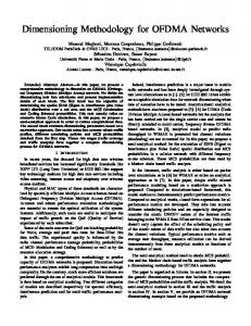
3. HEURISTICS DESCRIPTION 3.1 Genetic Algorithm This heuristic assumes that, for each traffic trunk, we have a set of candidate paths to chose the associated LSP. These paths are generated through an N-shortest paths computation algorithm9. This adds another degree of freedom to our problem: the number of candidate paths. A small number limits the set of solutions, possibly neglecting some of the best ones. A large number will increase the complexity of the algorithm, making it harder to converge to good solutions. Each solution is represented as a chromosome composed of N genes, where N is equal to the number of traffic trunks. Each gene contains a number that indicates one of the candidate paths, as depicted in Figure 1.
Figure 1: A chromosome representing a solution for 8 traffic trunks.
The information contained in a chromosome along with the specification of the candidate paths defines the x variables. To determine the y variables, the bandwidth required at each edge is calculated as the sum of the bandwidth demand of all traffic trunks, whose LSPs use the edge. Then, the set of transmission facilities that provides this bandwidth at the lowest cost is chosen from a previously ordered list of sets. This list is ordered by increasing amount of bandwidth and does not include the sets that provide an already existing bandwidth capacity at a greater cost. For problem P2, such list consists of sets with only one transmission facility. The evolution of the population is based on a mutation operator and a two points crossover operator10. The selection of individuals for the crossover operation is based on roulette wheel selection. The merit function is given by:
1 c x − cmin + α (cmax − cmin ) f ( x) = 1 c − cmin + α (cmax − cmin ) i∈ X i
(7)
∑
where f(x) is the probability of solution x of being selected; cx is the cost of solution x; cmin is the cost of the best solution in the population; cmax is the cost of the worst solution in the population; α is a parameter that defines the grade of selectivity (a smaller value of α implies that the solutions with the higher costs have less chances of being chosen for crossover). At the beginning of the genetic algorithm all genes in the population are assigned random values uniformly chosen between [0; NKP[, where NKP is the number of candidate paths. This means that we begin with solutions of random candidate paths for all the LSPs. Then, for the next iterations, new solutions are generated through selection and crossover and the application of the mutation operator to a given percentage of the genes of the new population. The new populations generated replace all the solutions of the old populations. The solution of the genetic algorithm is given by the solution with lower cost among all solutions of all generated populations. 3.2 Greedy based heuristic This heuristic is based on running a simple greedy algorithm several times. The algorithm is defined as follows: Repeat for a given amount of time: Randomly sort the LSPs For each LSP do: Establish the LSP through the path that requires the least cost in additional transmission facilities Deploy the additional transmission facilities Reserve the associated LSP traffic trunk bandwidth along the chosen path Evaluate the solution and if it is the best found so far, save it as the final solution. Remove all the transmission facilities The establishment of each LSP through the least cost path takes into account the already deployed transmission facilities and the exceeding bandwidth available at each edge. If the bandwidth of the traffic trunks assigned to an LSP can be established through an edge with exceeding bandwidth, then the cost of the edge is set to zero; if not, the edge cost is equal to the difference in cost between the new set and the already installed set of transmission facilities. 3.3 Lagrangean heuristic The lagrangean heuristic implementation is based on previous published work7,8. In each of the iterations, a feasible solution is determined based on the values of the x variables of the lower bound solution provided by the lagrangean relaxation technique11. Given a set of lagrangean multipliers λ{i, j } , the lagrangean lower bound program (LLBP) is defined as: Minimize:
∑ ∑ (λ{ { } i , j ∈A k∈K
i , j }bk
)x{ki, j} + ∑ ∑ (C{ti, j} − λ{i, j}α t )y{ti, j}
(8)
{i , j}∈A t∈T
subject to constraints (2), (4) and (5) for problem P1 or (2), (5) and (6) for problem P2. The first part of (8) (the member that depends on the x variables) is calculated through the use of a shortest path algorithm for each LSP. For problem P1, the second part of (8) is calculated by replacing the y variables with: 0, C {ti , j } ≥ λ{i , j}α t t y{, } = t t i j Y{i , j }, C {i , j } < λ{i , j }α t
(9)
For problem P2 the second part of (8) is given by:
∑ { }
(
)
min min C {ti , j } − λ{i , j }α t ,0 t∈T i , j ∈A
(10)
In this case and for each edge {i,j}, variables y t are all zero if all terms C {ti , j } − λ {i , j }α t are positive or the variable {i , j } yt is set to one for the index t whose term C {ti , j } − λ {i , j }α t is minimum. {i , j } Based on the variables x of the solution of LLBP, a feasible solution (variables y) is determined in the same way as described for the genetic algorithm: it is based on a previously ordered list of sets of transmission facilities. Given a set of lagrangean multipliers λ{i, j } , a new set is computed through sub-gradient optimisation12. Let ZLB be the current lower bound to the problem, ZUB a feasible solution and π a relaxation parameter in the range ]0; 2]. The procedure is as follows: Set the lagrangean multipliers equal to zero Set π equal to 2 Repeat for a given amount of time Solve LLBP with the current set of lagrangean multipliers to obtain ZLB Determine a solution based on the values of the x variables of ZLB to obtain y {ti , j } Evaluate the solution: if it is the best found so far, set ZUB equal to its cost and save it as the final solution Calculate the subgradients as: G{i , j } =
∑ b x{ k
k∈K
k i, j}
−
∑α t∈T
t
yt {i , j }
Calculate T as: π (Z UB − Z LB ) T= 2 G{i , j } {i , j }∈A Update the lagrangean multipliers as: λ{i , j } = max 0, λ{i , j } + TG{i , j }
∑(
)
(
)
(11)
(12)
(13)
If ZLB has not improved in the last 40 iterations halve the value of π
3.4 Heuristic Enhancements Both greedy based (section 3.2) and lagrangean algorithms (section 3.3) are iterative processes that try to generate a feasible solution in each iteration. In this section, two heuristic enhancement algorithms are proposed that use each feasible solution found by previous heuristics as the starting basis to find better feasible solutions. The first proposed heuristic enhancement (named E1) is defined as follows: Repeat for a given amount of time: Perform an iteration of the greedy/lagrangean heuristic to obtain a solution Evaluate the solution and if it is the best found so far, save it as the final solution If the solution is feasible, perform for a given number of iterations NSI: Determine a random order for the LSPs Repeat until all LSPs have been removed and re-established Remove the transmission facilities required for N LSPs according to the random order For each of the N removed LSPs do: Establish the LSP through the least cost path in additional transmission facilities Install the required network resources and reserve the associated LSP traffic trunk bandwidth along its path Evaluate the solution and if it is the best found so far, save it as the final solution The procedure of establishing the LSP through the least cost path is done in the same way as described in the greedy based heuristic. The evaluation of a solution is performed by adding the bandwidth of the associated LSPs traffic trunk that cross each edge, and by choosing the least cost set of transmission facilities that provides that bandwidth at the edge. With this enhancement algorithm, a total of NSI×NL/N new solutions are generated for each iteration of the
main heuristic, where NL is the total number of LSPs, N is the number of LSPs to be removed simultaneously and NSI is the number of iterations of the enhancement heuristic. The second proposed heuristic enhancement (named E2) has a somewhat similar behaviour. In this case however, we remove and re-establish all LSPs that cross a randomly chosen edge. By doing so, we hope to decrease the amount of bandwidth required at that edge by trying to establish some LSPs through other edges with exceeding bandwidth available. The enhancement algorithm E2 is defined as follows: Repeat for a given amount of time: Perform an iteration of the greedy/lagrangean heuristic to obtain a solution Evaluate the solution and if it is the best found so far, save it as the final solution If the solution is feasible, perform for a given number of iterations NSI: Chose a random edge of the network graph Remove the allocated transmission facilities for all the LSPs established through this edge For all of the LSPs whose resources were removed do: Establish the LSP through the least cost path in additional transmission facilities Install the required network resources and reserve the associated LSP traffic trunk bandwidth along its path Evaluate the solution and if it is the best found so far, save it as the final solution With this enhancement a total of NSI new solutions are generated for each of the main heuristic iterations.
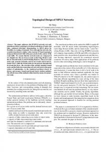
4. COMPUTATIONAL RESULTS For computational results, we have considered two fictional networks with different number of nodes and edges. The number of nodes and edges chosen was (50; 100) and (100; 200). The network topologies are displayed in Figure 2. The available transmission facility types and switching costs are: (34Mbps, 10); (155 Mbps, 35); (622Mbps, 130); (2488 Mbps, 450). The transmission cost per unit of length is 1 for all transmission facilities.
Figure 2: The network graphs used (50 nodes network and 100 nodes network)
For each network, we have considered the support of three services: service 1 with a bandwidth of 64 Kbps for each packet flow reservation, service 2 with a bandwidth of 128 Kbps for each packet flow reservation and service 3 with a bandwidth of 2 Mbps for each packet flow reservation. Ten different dimensioning problems were randomly generated for each network. In each problem, 80% of nodes were randomly selected to be edge router locations for each service. Then, traffic trunks between all pairs of edge routers were considered. The maximum number of packet flows of each traffic trunk was randomly selected between 1-50 for service 1, 1-30 for service 2 and 1-5 for service 3. The maximum bandwidth of each traffic trunk is given by the product of its maximum number of packet flows and the bandwidth reservation of each individual packet flow.
The computational results were obtained on a 300MHz Pentium II with 64Mb RAM running MS Windows2000 OS for the 50 node network dimensioning problems and a 350MHz Pentium II with 64Mb RAM running MS Windows98 OS for the 100 node network dimensioning problems. The heuristics were used with the following parameters (chosen based on previous experience13): Genetic algorithm: population size of 100 individuals; mutation probability of 1%, α=0.01; NKP=5 Greedy based heuristic with E1: NSI=1000; N=5 Greedy based heuristic with E2: NSI=1000 Lagrangean heuristic with E1: NSI=5; N=5 Lagrangean heuristic with E2: NSI=100 for the 50 node dimensioning problems NSI=10 for the 100 node dimensioning problems All 20 dimensioning problems were solved considering the two dimensioning models P1 and P2. For all heuristics, a maximum computing time of 3 hours was given and the the algorithm would stop if the best solution did not improve within 30 minutes. Table 1 shows the average gains of each group of 10 problems relative to lagrangean heuristic ((LH– Heuristic)/LH) for the other heuristics: genetic algorithm (GA); greedy based heuristic (GH); greedy based heuristic with E1 (GHE1); greedy based heuristic with E2 (GHE2); lagrangean heuristic with E1 (LHE1); lagrangean heuristic with E2 (GHE2). A cell with “N/F” indicates that a feasible solution was not found within the time limit. Whenever a number n is shown between brackets, it means that the heuristic has found a feasible solution only for n of the 10 dimensioning problems. Table 2 shows the average elapsed times (in seconds) between the start of the algorithm and the finding of the best solution.
P1 – 50 nodes P1 – 100 nodes P2 – 50 nodes P2 – 100 nodes
GA -12,11% -33,95% -31,93% N/F
GH -25,40% -121,10% -49,21% -47,37% (1)
GHE1 -9,64% -86,64% -10,54% -9,71% (4)
GHE2 -5,87% -82,11% 7,93% -1,44% (2)
LHE1 2,25% -15,15% 4,73% 7,00%
LHE2 8,63% 3,32% 16,20% 12,23%
Table 1: Average of gains compared with lagrangean heuristic results
P1 – 50 nodes P1 – 100 nodes P2 – 50 nodes P2 – 100 nodes
LH
GA
GH
GHE1
GHE2
LHE1
LHE2
4,9 135,2 17,4 224,1
3514,7 7526,3 2578,5 N/F
1077,8 1586,1 1743,3 330,0
1721,0 9982,0 2860,5 2428,3
1009,2 988,7 2358,6 980,5
1294,8 4593,1 2656,5 3318,3
2390,0 2334,4 2552,5 1970,0
Table 2: Average of computing times (seconds)
The computational results show that heuristics based on Lagrangean relaxation with sub-gradient optimization achieve the best results. In particular, the combination of this heuristic with the enhancement algorithm E2 has reached significant gains specially for dimensioning model P2. These gains are obtained through an increase on computing times. However, we consider that the maximum computing time allowed for the heuristics (3 hours) is reasonable for a network-planning task and, therefore, this combined heuristic represents an improvement on the ability of calculating good feasible solutions for large-scale MPLS networks. Concerning the performance of the two proposed enhancement algorithms, it is clear that the second one is better since the average gains are always better when E2 is applied, independently of the problem class and of the basic heuristic. Concerning the other approaches, the genetic algorithm proposed has very poor results. The greedy based heuristics perform significantly worse than lagrangean based heuristics.
In short, a guideline for solving the aforementioned problems would be to use the lagrangean heuristic for time critical situations or extremely large instances and the lagrangean heuristic with the second enhancement to obtain more refined lower cost solutions.
5. CONCLUSIONS In this paper, we have presented different heuristic approaches for dimensioning large-scale MPLS networks. We have addressed two slightly different dimensioning problems that arise in MPLS technology. The first one has been previously addressed where a heuristic based on Lagrangean relaxation with sub-gradient optimisation was proposed. In this paper, we have shown the merit of this heuristic in solving MPLS large-scale network dimensioning problems by comparing its results with other well-known heuristic approaches (genetic algorithms and greedy based algorithms). Moreover, we have improved this heuristic through the introduction of enhancement algorithms, which significantly decrease the cost of the computed feasible solutions at the cost of an increase of computing time.
AKNOWLEDGEMENTS This work was part of project PRAXIS/P/EEI/12135/98 DOTE "Dimensioning and Resource Management Optimization Algorithms for Telecommunications Networks", funded by Fundação para a Ciência e Tecnologia, Portugal. We also acknowledge the support of Portugal Telecom Inovação. C. Borges also wishes to thank Fundação para a Ciência e a Tecnologia for support under grant BM/21073/99.
REFERENCES 1. 2. 3. 4. 5. 6. 7.
8. 9. 10. 11. 12. 13.
Xipeng Xiao, Alan Hannan, Brook Bailey, “Traffic Engineering with MPLS in the Internet”, IEEE Network, March/April 2000. Special issue on “Multiprotocol Label Switching”, IEEE Communications Magazine, 37(12), pp. 36-68, December 1999. E. Rosen, A. Viswanathan, R. Callon, “Multiprotocol Label Switching Architecture”, IETF RFC 3031, January 2001. D. Awduche, J. Malcolm, J. Agogbua, M. O’Dell, J. McManus, “Requirements for Traffic Engineering Over MPLS”, IETF RFC 2702, September 1999. T. Magnanti, P. Mirchandani, R. Vachani, “Modeling and Solving the Two Facility Capacitated Network Loading Problem”, Operations Research, 43(1), pp.142-156, 1995. D. Bienstock, O. Günlük, “Capacitated Network Design – Polyhedral Structure and Computation”, INFORMS Journal on Computing, 8(3), pp. 243-257, 1996. A. Sousa, R. Valadas, L. Cardoso, A. Duarte, “ATM Network Dimensioning for Mixed Symmetrical and Assymetrical Services with Dynamic Reconfiguration in a Multi-Network Provider Environment”, Third IFIP Workshop on Traffic Management and Design of ATM Networks, pp. 5/1-5/15, England, 1999. D. Medhi, “Multi-Hour, Multi-Traffic Class Network Design for Virtual Path-Based Dynamically Reconfigurable Wide-Area ATM Networks”, IEEE/ACM Transactions on Networking, 3(6), December 1995. Ernesto Martins, Marta Pascoal, José dos Santos, “A New Algorithm for Ranking Loopless Paths”, Research Report, CISUC, May 1997. Mitsuo Gen, Runwei Cheng, Genetic Algorithms and Engineering Optimization, Wiley-Interscience, 2000. J. Beasley, “Lagrangean Relaxation”, Modern Heuristic Techniques for Combinatorial problem, Ed. by Colin Reeves, Blackwell Scientific publications, 1993. M. Held, P. Wolfe, H. Crowder, “Validation of subgradient optimisation”, Mathematical Programming, 6, pp. 6288, 1974. Carlos Borges, Heuristics for the Dimensioning Problem of Multi-Service Telecommunication Networks (in Portuguese), M.Sc. Dissertation, pp. 92-93, Aveiro, submitted April 2001.