Keywords: Tool wear; Process monitoring; Turning; Hidden Markov models; ... The application of HMMs in process monitoring is of great interest because of their.
Hidden Markov Model-based Tool Wear Monitoring in Turning Litao Wang, Mostafa G. Mehrabi, and Elijah Kannatey-Asibu, Jr. Department of Mechanical Engineering Engineering Research Center for Reconfigurable Machining Systems University of Michigan, Ann Arbor, MI 48109-2125
Abstract This paper presents a new modeling framework for tool wear monitoring in machining processes using hidden Markov models (HMMs). Feature vectors are extracted from vibration signals measured during turning. A codebook is designed and used for vector quantization to convert the feature vectors into a symbol sequence for the hidden Markov model. A series of experiments are conducted to evaluate the effectiveness of the approach for different lengths of training data and observation sequence. Experimental results show that successful tool state detection rates as high as 97% can be achieved by using this approach.
Keywords : Tool wear; Process monitoring; Turning; Hidden Markov models; Wavelet transform; Feature extraction; Feature
vectors;
Observation
sequence;
Vector
quantization.
1. Introduction In modern and unmanned machining systems, including dedicated transfer lines, flexible manufacturing systems, and Reconfigurable Manufacturing Systems (RMS), one crucial component is a reliable and effective monitoring system to monitor process conditions, and to take remedial action when failure occurs, or is imminent. Sensing of
1
gradual tool wear is a key element in producing high quality parts. Undesirable effects such as tool wear and tool breakage may result in deterioration in surface finish and dimensional accuracy of the finished parts, and possible damage to the workpiece and machine [1]. For modern machine tools, 20% of downtime is attributed to tool failure [2]. A reliable monitoring system would minimize these problems and allow optimum utilization of tool life, which is highly desirable. Early work on tool wear monitoring focused on time series methods and frequency domain analysis [3-6]. With these methods, a threshold va lue needs to be set between the normal and abnormal states of tool. However, the threshold value varies with time and cutting conditions.
To improve the performance, more advanced methods, such as
pattern recognition analysis [7-10] and statistical methods [11-14], have been developed. These methods have gained various degrees of success in practical applications for monitoring cutting processes. More recently, artificial neural networks (ANN) and their combination with fuzzy logic models have been extensively applied to the area of tool wear estimation [15-20]. ANNs have the advantages of superior learning, noise suppression, and parallel computation abilities. However, successful implementation of an ANN-based monitoring system strongly depends on proper selection of the type of network structure and amount of training data, which are not always available, especially for the abnormal tool state. In this research, a modeling framework based on hidden Markov models (HMMs) was applied to classify features of the sensor signals. The application of HMMs was motivated by its successes in speech recognition.
HMMs have proven to be
tremendously useful in speech recognition where signals are inherently time varying.
2
The application of HMMs in process monitoring is of great interest because of their strong capability in representing machining signals, which are non-stationary, by statistical parameters.
Furthermore, in pattern recognition, there always exists
uncertainty, randomness and incompleteness originating from various sources. Stochastic models are known to deal with these problems efficiently by using probabilistic models, thus widely used in signal modeling. Among various stochastic approaches, HMMs have proven very effective in modeling both dynamic and static signals [21]. Heck and McClellan [22] presented a continuous density, left-right HMM-based approach for tool wear detection and prediction. Owsley et al. [23] applied a semicontinuous HMM to classify the features extracted using self-organizing feature maps in drilling monitoring. Even after this paper was submitted for review, Ertunc et al. [24] published a paper using HMMs to track the progress of tool wear in drilling. Vibration signals were used to detect tool wear states in this research. Tool wear in turning was thoroughly studied. Vibration signals in the feed direction contain reliable information for monitoring tool wear, and this has also been proven by other researchers [25]. The paper is organized as follows. The principle of discrete hidden Markov models is briefly described in section 2. Section 3 introduces the procedure for hidden Markov model-based process monitoring. Following description of the experimental setup in section 4, feature extraction method and the vector quantization technique are discussed in section 5. Section 6 presents the application of hidden Markov model-based process
3
monitoring in turning and a series of experimental results are reported. The conclusions are given in section 7.
2. Discrete Hidden Markov Models The hidden Markov model (HMM) is extended from the concept of Markov chain [26].
HMMs are divided into continuous and discrete models according to their
probability density description [27]. Discrete HMMs are selected for this research, because they can represent any distribution as no assumptions are made about the underlying distribution of the observed symbols. Consider a first-order N-state Markov chain as illustrated for N=3 in Figure 1. The system can be described as being in one of the N distinct states, S1 , S2 , ? , SN, at any time instant t. The corresponding HMM for discrete symbol observations is characterized by the following:
i) N, the number of hidden states in the model. The hidden states are interconnected in such a way that any hidden state can be reached from any other hidden state. ii) M, the number of distinct observation symbols per hidden state. We denote the individual symbols as V = {v1 , v2 , ? , vM}. iii) The state-transition probability distribution A = [aij] where aij = P(qt =Sj | qt-1 =Si), 1 ? i, j ? N
(1)
where qt denotes the actual hidden state at time t. iv) The observation symbol probability distribution, B = [bjm ], in which bjm = P(ot =vm | qt =Sj), 1 ? m ? M
4
(2)
defines the symbol distribution in state j, and ot is the observation at time t. v) The initial state distribution ? = [? i] in which ? i = P(qi=Si), 1 ? i ? N
(3)
a11
a22 a12
1
2 a21 a13
a32
a31
a23 3 a33
Figure 1 A first-order, three state hidden Markov model A complete specification of a HMM requires three sets of probability measures A, B and ? . For convenience, we use the compact notation ? = (A, B, ? )
(4)
to indicate the complete parameter set of the model. To better understand the principle of HMM, let us consider the decision- making process of an earthworm shown in Figure 2. The earthworm can only ‘observe’ humidity using terms such as dry, damp, and soggy, which serve as observation symbols. In this model, there are three hidden states (sunny, cloudy, and rainy), and three observation symbols for each hidden state. The earthworm generates a finite observation sequence of humidity for a period of time, from which the current season is derived.
5
Hidden states dry
soggy
Results
sunny rainy
‘Summer’ ‘Winter’
cloudy damp
Figure 2 Decision- making process of an earthworm In machining process monitoring, features extracted from the measured signals are observation symbols. The results (sharp tool or worn tool) will be obtained by a similar modeling.
3. HMM-based Process Monitoring Similar to other process monitoring strategies, the proposed method consists of two phases: training and detection. Let us assume we have S tool states to be monitored and that each tool state is modeled by a distinct HMM. Further assume, for simplicity of notation, that for each tool state we have finite training sets where each training set constitutes an observation sequence O = (o1 , o2 , ? , oT ) of some appropriate representation of the characteristics of the tool state. The following steps are involved in design of the process monitoring system:
Step I:
The first step is to build an HMM ? s for each tool state s. In other words,
we must estimate the model parameters (A, B, ? ) that optimize the likelihood of the training set observation sequence for the sth tool state or maximize P(O|? s ), the
6
probability of observation sequence O given model ? s. The method we used is the Baum-Welch re-estimation algorithm, also known as the expectation maximization (EM) approach. Figure 3 shows the flow chart of the training procedure. Training sets of signals
Discrete Wavelet Transform Wavelet coefficients Feature Extraction
Vector Quantization
Codebook (K vectors)
Observation sequence O HMM training HMM parameters (A, B, ?)
Figure 3 Flow chart of the HMM training procedure Step II:
The procedure for detecting the condition of an unknown tool is depicted
in Figure 4.
As shown, features of the input signals (after calculating wavelet
coefficients) are extracted and feature vectors are formed for vector quantization. This is then followed by calculation of model likelihood for all possible models, P(O|? s), 1 ? s ? S, which is the probability of the observation sequence, given the model. The model with the highest likelihood is considered to be the best candidate for representing the tool condition, i.e.,
s* ? arg max [ P (O | ? s )]
(5)
1? s ? S
7
Input signals from unknown tool state
Discrete Wavelet Transform Wavelet coefficients Feature Extraction Codebook (K vectors)
Vector Quantization Observation sequence O HMM for tool state 1 ?1
Likelihood Computation
HMM for tool state 2 ?2
P(O|?1 )
Likelihood Computation
?
HMM for tool state S
?
?S
Likelihood Computation
P(O|?2 )
P(O|?S)
Select Maximum
Index of tool state s *
Figure 4 Block diagram of the procedure for tool condition detection Details of a numerical example showing these steps are provided in sections 5 and 6.
4. Experimental Setup and Data Collection Cutting tests were performed on a 30hp CNC lathe. An accelerometer was mounted on the cutting tool holder attached to the turret, as shown in Figure 5, to measure vibration in the feed direction. This is because earlier work indicates that vibration signals in the feed direction are more sensitive than those in the cutting and radial directions in detecting tool wear [25].
8
The vibration signals were first amplified using a charge amplifier and low-pass filtered with a cut-off frequency of 6 kHz, and then sampled at 100 kHz using a 12-bit data acquisition card. Every data set was 0.5 seconds in length, equivalent to 50 k data points. Cutting was started with a sharp insert and stopped every minute for tool wear measurements using a toolmaker’s microscope. An average flank wear height of at least 0.3 mm or the maximum wear height of 0.6 mm was considered to be a worn edge. This limit was selected in accordance with ISO 3685 which defines effective tool life for carbide tools [28].
workpiece
Tool holder
Accelerometer
Signal Processing
Turret Anti-alias Filter
Amplifier
Figure 5 Experimental setup The experiments were conducted to detect two tool states, namely a sharp tool and a worn tool. The workpiece and cutting tool materials are shown in Table 1. Table 1 Workpiece and cutting tool Cutting Tool Coating
Carbide insert TNMA-432 VC2 None AISI 8620 steel 7 inches long, 2.25 inches diameter
Workpiece
9
The cutting conditions were varied. Three levels of feed rate, 0.004, 0.005, and 0.006 inch/rev, were selected, and three different cutting speeds, 250, 300, and 350 sfpm, were used. The depth of cut was kept constant at 0.05 inch. No cutting fluid was applied in the turning process.
To avoid overheating, machining was periodically stopped for
cooling down.
5. Feature Extraction and Vector Quantization Details of feature extraction of the vibration signals using wavelet analysis are provided by Wang et al. [29]. Contrary to the other methods such as measuring cutting forces that use static characteristics of tool wear, we extract dynamic characteristics of tool wear from wavelet coefficients. Static analysis along is not robust within all the wear states. Typical vibration signals and variation of their wavelet coefficients for sharp and worn tools are shown in Figure 6(a)-(b).
In Figure 6(b), the horizontal axis
represents time, and the vertical axis represents the amplitude of coefficients. Scales 1-6 are equivalent to frequency bandwidths of the original signals from low to high. The frequency bandwidths corresponding to the first three scales are (781Hz, 1562Hz), (1562Hz, 3125Hz), and (3125Hz, 6250Hz) respectively.
(a)
Amplitude (Volts)
Vibration Signal (sharp tools)
Vibration Signal (worn tools)
3
3
2
2
1
1
0
0
-1
-1
-2
-2 0
10
20 30 time (msec)
40
50
0
10
10
20 30 time (msec)
40
50
(b)
Wavelet coefficients (sharp tool)
Wavelet coefficients (worn tool)
5 1 0 -5 2
3
4
5
6
51 0 -5 51 0 -5 51 0 -5 51 0 -5 51 0 -5 0
10
20 30 time (msec)
40
1
5 0 -5
2
5 0 -5
3
5 0 -5
4
5 0 -5
5
5 0 -5
6
5 0 -5
50
1
1
1
1
1
0
10
20 30 time (msec)
40
50
Figure 6 (a) Time domain vibration signals; (b) Variation of wavelet coefficients for different tool states The outcome of the discrete wavelet transform is a series of coefficient vectors representing the time-varying machining signal.
For convenience, we denote the
coefficient vectors as d j (k ) , j = 1, 2, ? , J, where J is the number of wavelet scales, and k represents discrete time. Each coefficient vector can be further represented by its average energy, which is defined as:
1 Tj 2 Ej ? ? d j (k ) T j k ?1
(6)
where Tj is the number of coefficients at each scale. The value of Tj is different for different scales, because the time spacing of wavelet coefficients varies with the resolution j.
11
The features are normalized by making the highest energy amplitude unity for each feature before any further processing. As a result, the observation features are made independent of the signal magnitudes. Each feature is a “unique” vector that corresponds to some characteristics of the tool states.
This ideal representation is, of course, impractical, because each coefficient
feature from the same tool state can have an infinite number of values.
Vector
quantization (VQ) is an efficient way of representing the time- frequency information of the signal. All the features can be represented by a small number of finite feature vectors, which is referred to as a codebook. Thus, determining the features of a time domain signal is equivalent to assigning a set of codebook labels (observation sequence) to that signal. The size of the codebook is equivalent to the number of distinct observation symbols in HMM. The HMM-based monitoring will exploit this observation sequence to determine tool states in an efficient manner. Figure 7 shows an example of a codebook consisting of ten elements in process monitoring. Any feature from this machining process can be represented by one of the elements in the codebook. To represent any input feature, all we need is the index of the codebook element that best matches the input vector. This is achieved by comparing the distance d between the input vector X and all of the vector elements Yi in the codebook and choosing the one for which the distance is smallest. The index I* of the quantized vector is given by
I * ? arg min [ d ( X ? Yi )]
(7)
i
Euclidean distance is often used in computing the distance between two vectors:
12
d ( X ? Yi ) ? ( X ? Yi )T ( X ? Yi )
(8)
Amplitude
A codebook in tool wear monitoring 1 0.5 0 11 0.5 0 11 0.5 0 11 0.5 0 11 0.5 0 11 0.5 0 11 0.5 0 11 0.5 0 11 0.5 0 11 0.5 0 1
2
3
4
5
6
scale
Figure 7 Feature elements in a codebook It should be mentioned that the design of a vector quantizer for a particular source is of fundamental importance. One popular algorithm for codebook design is the so-called LBG algorithm [30], which utilizes the nearest neighbor and centroid rules to perform an iterative descent procedure based on a finite training set representation of the source. This training process is repeated until the distortion falls below a pre-determined threshold value.
6. Results and Discussion To increase the reliability of the system, the vibration signals are split into a sequence of non-overlapping observations (frames).
The length of an observation must be
carefully chosen to reduce the computation time while at the same time containing enough information to capture the local features of the signal. Figure 8 sho ws a vibration signal for a sharp tool with an observation size of 5.
13
4 3 2 Amplitude
1 0 -1 -2 -3 O1
O5
O3
-4
O2
-5 0
O4
10
20
30
40
50
Time (ms)
Figure 8 An observed vibration signal from a sharp tool The features extracted from each observation constitute the feature vectors of the corresponding tool state. Typical feature vectors for sharp and worn tools are shown in Figures 9 - 11 (from different cutting conditions). Feature Vectors (sharp tool)
Feature Vectors (worn tool) 5 4 3 2 1
3 2 1
Amplitude
8 6 4 2 2 1.5 1 0.5
1
2
3
4
5
6
1
2
3
4
5
6
1
2
3
4
5
6
1
2
3
4
5
6
1
2
3
4
5
6
1
2
3
4
5
6
1
2
3 4 scale
5
6
6 4 2
31 2 1
2
3
4
5
6
1
2
3
4
5
6
1
2
3
4
5
6
6 4 2
5 4 3 2 1
3 2 1 4 2
scale
Figure 9 Feature vectors for sharp and worn tools (cutting speed: 300 sfpm; feed rate: 0.005 ipr)
14
Feature Vectors (sharp tool)
Feature Vectors (worn tool) 8 6 4 2
Amplitude
8 6 4 2 61 4 2
2
3
4
5
6
1
2
3
4
5
6
1
2
3
4
5
6
1
2
3
4
5
6
1
2
3
4
5
6
9 6 3 0
12 9 6 3 0 10 8 6 4 2
1
2
3
4
5
6
12 1 9 6 3 0 1 8 6 4 2
2
3
4
5
6
2
3
4
5
6
1
2
3
4
5
6
1
2
3
4
5
6
10 8 6 4 2
15 10 5
scale
scale
Figure 10 Feature vectors for sharp and worn tools (cutting speed: 250 sfpm; feed rate: 0.006 ipr) Feature Vectors (sharp tool)
Feature Vectors (worn tool) 5 4 3 2 1
12 8 4 0 1
2
3
4
5
6
Amplitude
15 10 5 15 10 5 24 16 8 0 20 15 10 5
1
2
3
4
5
6
1
2
3
4
5
6
1
2
3
4
5
6
1
2
3
4
5
6
1
2
3
4
5
6
6 4 2 1
2
3
4
5
6 8 6 4 2
1
2
3
4
5
6
1
2
3
4
5
6
5 4 3 2 1 8 6 4 2
1
2
3
4
5
6
scale
scale
Figure 11 Feature vectors for sharp and worn tools (cutting speed: 350 sfpm; feed rate: 0.004 ipr) The results are very repeatable. Referring to these figures, it can be seen that when the cutting tool is sharp, lower frequency vibration is mainly excited. As tool wear
15
progresses, other frequencies of vibration of the tool holder and machine structure may become excited [31], resulting in the higher frequency components becoming more dominant. The vibration data obtained from experiments was divided into two separate groups for training and testing. Each group contained at least 100 snapshots from a sharp tool and 100 snapshots from a worn tool; the duration of each snapshot was 50ms. The training data was used to train the HMMs, but the testing data was not used during training. The first task is to train the HMMs based on the data from different tool states. The initial parameters of the HMMs are chosen randomly. Different initial parameters will in general produce different HMMs. However, the sensitivity of the detection rate to deviation in the initial hidden state probabilities is low, as reported by Rabiner [32]. An example of observation symbol probability distribution (with 10 observation symbols determined by the size of the codebook) for a sharp tool, BS, and a worn tool, BW , is obtained as follows. ?0.1013 0.1525 0.1976 0.1447 0.0607 0.1129 0.0837 0.0978 0.0488 0.0000? Bs ? ??0. 1359 0.1359 0.0281 0.1314 0.2019 0.1229 0.1000 0.0856 0.0583 0.0000?? ??0. 0782 0.1578 0.1694 0.1039 0.1244 0.1247 0.1086 0.0844 0.0487 0.0000?? ?0.0000 0.0000 0.0000 0.0000 0.0000 0.0237 0.0403 0.0965 0.3194 0.5201? Bw ? ??0.0000 0.0000 0.0000 0.0000 0.0000 0.0226 0.0403 0.0895 0.3316 0.5160?? ??0.0000 0.0000 0.0000 0.0000 0.0000 0.0234 0.0393 0.0953 0.3187 0.5233??
For a sharp tool, the observatio n symbol probability bjm , where m=1, 2, ? , 10, is very low for m greater than 7. However, the observation symbol probability for a worn tool is mainly distributed at m=9 and m=10.
16
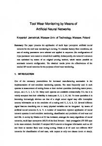
The performance of the HMM-based monitoring system was evaluated for different lengths of training data. Figure 12 shows the effect of lengths of training data on the detection rate. The adopted model was a 3-state HMM, with an observation sequence length of 5 and a codebook size of 10. It shows that the detection rate reaches as high as 97 percent even when a very short length of training data (2 s) is used. Given a limited amount of training data, traditional classifiers usually have a difficult time distinguishing the tool states and thus exhibit poor performance. In contrast, the discrete HMMs make more efficient use of the training data, and additional training data does not significantly improve their performance.
100
Detection Rate (%)
99 98 97 96 95 worn tool sharp tool
94 93 0.5
1
1.5
2 2.5 3 3.5 Length of training data (s)
4
4.5
5
Figure 12 Detection rate versus length of training data (3-state HMM with observation sequence length of 5 and codebook size of 10) Further study of the results suggests that an increase in observation sequence length improves the performance of the monitoring system in predicting tool conditions, as shown in Figure 13. The highest performance was achieved at observation sequence length of 4 and above.
17
100
Detection Rate (%)
98 96 94 92 90 sharp tool worn tool
88 86 2
3
4 Observation Sequence Length
5
6
Figure 13 Detection rate versus observation sequence length (3-state HMM with codebook size of 10) Extensive experiments were conducted to verify the reliability of the results. The system was trained using a 3-state HMM with codebook size of 10 and observation sequence length of 5. The results of detection are better visualized by plotting the probability patterns in the decision space. The axes of the decision space constitute the individual classes for different tool states. Figure 14 shows the pattern distribution for randomly selected 60 samples for sharp and worn tools. The distinct separation for different tool states is more evident in this plot. Each pattern that crosses the boundary line (the diagonal line) is essentially misclassified. It should be mentioned that the indirectly measured signals from a sharp tool occasionally reflect the characteristic of a worn tool, and vise versa. Thus the drastic misclassification is not surprising.
18
% 40 sharp tool worn tool 60 samples each
Probabbility model II (worn tool)
35 30 25 20 15 10 5 0
0
5
10 15 20 25 30 Probabbility model I (sharp tool)
35
40 %
Figure 14 Decision space for sharp and worn tools Results of three experiments performed at different dates are listed in Table 2. For example in test 2, sharp tools were correctly detected 98 out of 100 times, resulting in a 98% detection rate. The corresponding rate for worn tools was 96%, with 96 out of 100 times being correctly detected. Overall, a detection rate of up to 97% was achieved based on the proposed approach. The reported success rate of other methods in detecting tool wear in turning was from 82% to 96% [10, 14, 16].
Table 2 Detection results in various tests
Sharp tool Worn tool Detection rate
Test 1 Sharp Worn tool tool 97 1 3 99 97% 99%
Test 2 Sharp Worn tool tool 98 4 2 96 98% 96%
19
Test 3 Sharp tool 98 2 98%
Worn tool 3 97 97%
7. Conclusions In this paper, a new approach for tool monitoring was introduced by using hidden Markov models (HMMs). The proposed method is model based, where the models are trained using data from a machining process. Therefore no assumptions are made with regard to the measured signals. Training the models on process data helps to ensure the validity of the models. The effectiveness of the approach was evaluated under different conditions (e.g., different lengths of training data and variations of observation sequence length). Successful tool state detection was even achieved when the length of training data was as small as 2 s. Extensive experimental results indicate that an average detection rate (for sharp and worn tools) as high as 97% can be achieved. Therefore, the discrete HMM combined with wavelet analysis method is a successful tool for process monitoring.
Acknowledgements The authors are pleased to acknowledge the financial support of the Engineering Research Center for Reconfigurable Machining Systems (NSF grant # EEC-9529125), and the assistance from Ming-Chyuan Lu by providing some of the experimental data.
References [1] Kuo, R. J., and Cohen, P. H., 1999, “Multi-sensor Integration for On- line Tool Wear Estimation Through Radial Basis Function Networks and Fuzzy Neural Network,” Neural Networks, Vol. 12, pp. 355-370. [2] Kurada, S., and Bradley, C., 1997, “A Review of Machine Vision Sensors for Tool Condition Monitoring,” Computer in Industry, Vol. 34, pp. 55-72. [3] Taraman, K., Swando, R., and Yamauchi, W., 1974, “Relationship Between Tool Forces and Flank Wear,” SME Tech Pap, March, 15p. [4] Fromson, R., and Shum, L. Y., 1984, “Tool Wear and Tool Failure Monitoring System,” Westinghouse Electric Corp., USA, USP 04442494.
20
[5] Liang, S. Y., and Dornfeld, D. A., 1989, “Tool Wear Detection Using Time Series Analysis of Acoustic Emission,” ASME Journal of Engineering for Industry, Vol. 111, pp. 199. [6] El-wardany, T. I., Gao, D., and Elbestawi, M. A., 1996, “Tool Condition Monitoring in Drilling Using Vibration Signature Analysis,” Int. J. Mach. Tools Manufacture. Vol. 36, pp. 687-711. [7] Emel, E., and Kannatey-Asibu, E., 1988, “Tool Failure Monitoring in Turning by Pattern Recognition Analysis of AE Signals,” ASME Journal of Engineering for Industry, Vol. 110, pp. 137-145. [8] Emel, E., and Kannatey-Asibu, E., 1989, “Acoustic Emission and Force Sensor Fusion for Monitoring the Cutting Process,” Int. J. Mech. Sci., Vol. 31, pp. 795-809. [9] Ko, T. J., Cho, D. W., and Lee, J. M., 1992, “Fuzzy Pattern Recognition for Tool Wear Monitoring in Diamond Turning,” Annals of CIRP, Vol. 41, pp. 125-128. [10] Lee, W. B., Cheung, C. F., Chiu, W. M., and Chan, L. K., 1997, “Automatic Supervisio n of Blanking Tool Wear using Pattern Recognition Analysis,” Int. J. Mach. Tools Manufacture. Vol. 37, pp. 1079-1095. [11] Lim, G. H., 1995, “Tool- wear Monitoring in Machine Turning,” Journal of Materials Processing Technology, Vol. 51, pp. 25-36. [12] Miyoshi, Y., 1996, “Abnormal Cutting State Detection Using Model Parameters,” Int. J. Japan Soc. Prec. Eng., Vol. 30, No. 1, pp. 41-46. [13] Ravindra, H. V., Srinivasa, Y. G., and Krishnamurthy, R., 1997, “Acoustic Emission for Tool Condition Monitoring in Metal Cutting,” Wear, Vol. 212, pp. 78-84. [14] Kumar, S. A., Ravindra, H. V., and Srinivasa, Y. G., 1997, “In-process Tool Wear Monitoring Through Time Series Modeling and Pattern Recognition,” International Journal of Production Research, Vol. 35, pp. 739-751. [15] Dornfeld, D. A., 1990, “Neural Network Sensor Fusion for Tool Condition Monitoring,” Annals of CIRP, Vol. 39/1, pp. 101-105. [16] Wang, Z., and Dornfeld, D. A., 1992, “In-process Tool Wear Monitoring Using Neural Networks,” Japan/USA Symposium on Flexible Automation, Vol. 1, pp. 263269. [17] Lin, C. T., and Lee, C. S. G., 1994, “Reinforcement Structure/Parameter Learning for Neural Network Based Fuzzy Logic Control Systems,” IEEE Transaction on Fuzzy Systems, Vol. 2, pp. 46-63. [18] Das, S., Chattopadhyay, A. B., and Murthy, A. S. R., 1996, “Force Parameters for On-line Tool Wear Estimation: A Neural Network Approach,” Neural Network, Vol. 9, pp. 1639-1645. [19] Lin, S. C., and Ting, C. J., 1996, “Drill Wear Monitoring Using Neural Networks,” Int. J. Mach. Tools Manufacture. Vol. 36, pp. 465-475. [20] Kuo, R. J., and Cohen, P. H., 1998, “Intelligent Tool Wear Estimation System Through Artificial Neural Networks and Fuzzy Modeling,” Artificial Intelligence in Engineering, Vol. 12, No. 3, pp. 229-242. [21] Cho, Wongyu, Lee, S. W. and Kim, Jin H., 1995, “Modeling and Recognition of Cursive Words with Hidden Markov Models”, Pattern Recognition, Vol. 28, No. 12, pp. 1941-1953.
21
[22] Heck, L. P., and McClellan, J. H., 1991, “Mechanical System Monitoring us ing Hidden Markov Models,” IEEE International Conference on Acoustic, Speech and Signal Processing Proceedings 91, Vol. 3, pp. 1697-1700. [23] Owsley, L. M. D., Atlas, L. E., and Bernard, G. D., 1997, “Self-organizing Feature Maps and Hidden Markov Models for Machine-tool Monitoring,” IEEE Transactions on Signal Processing, Vol. 45, No. 11, pp. 2787-2798. [24] Ertunc, H. M., Loparo, K. A., and Ocak H., 2001, “Tool Wear Condition Monitoring in Drilling Operations using Hidden Markov Models (HMMs),” Int. J. Mach. Tools Manufacture. Vol. 41, pp. 1363-1384. [25] Lee, M. Y., Thomas, C. E., and Wildes, G., 1987, “Review – Prospects for Inprocess Diagnosis of Metal Cutting by Monitoring Vibration Signals,” J. Mat. Sci., Vol. 22, pp. 3821-3890. [26] Rabiner, L. R., 1989, “A Tutorial on Hidden Markov Models and Selected Applications in Speech Recognition,” Proc. IEEE, Vol. 77, No. 2, pp. 257-286. [27] Lee, Kai-Fu, 1989, Automatic Speech Recognition, Kluwer Academic Publishers. [28] ISO 3685, 1993, “Tool-Life Testing with Single-point Turning Tools,” ISO 3685:1993(E), International Standard, Second Edition, 1993-11-15. [29] Wang, L., Mehrabi, M. G., and Kannatey-Asibu, Jr., E., 2001, “Tool Wear Monitoring in Machining Processes Through Wavelet Analysis,” to be published in Transactions of NAMRI/SME, Vol. XXIX. [30] Linde, Y., Buzo, A., and Gray, R. M., 1980, “An Algorithm for Vector Quantizer Design,” IEEE Trans. Commun., Vol. 28, pp. 84-95. [31] Lu, M. C., and Kannatey-Asibu, Jr., E., 2000, “Analysis of Sound Signal Characteristics Associated with Adhesive Wear in Machining”, Transaction of NAMRI, Vol. XXVIII, pp. 257-262 [32] Rabiner, J. C., 1985, “Some Properties of Continuous Hidden Markov Model Representations,” AT&T Technical Journal, Vol. 64, No. 6, pp. 1251-1269.
22