Raigad, Maharashtra- 402 103 (India) b Mechanical Engineering Department, Indian Institute of Technology,. Kharagpur, West Bengal- 721 302 (India). Abstract.
JoumaIof
Materials Processing Technology
ELSEVIER
Journal of Materials Processing Technology 63 (1997) 187-192
Neural-Networks-Based Tool Wear Monitoring in Turning Medium Carbon Steel Using a Coated Carbide Tool
a
b
b
Santanu Das, P.P. Bandyopadhyay and A.B. Chattopadhyay a Mechanical Engineering Department, Dr. Babasaheb Ambedkar Technological University, Lonere. Dist.- Raigad, Maharashtra- 402 103 (India) b Mechanical Engineering Department, Indian Institute of Technology, Kharagpur, West Bengal- 721 302 (India)
Abstract Appropriate on-line tool condition monitoring is essential for sophisticated and automated modem machine tools for aiding better tool management. It enables higher productivity and safety to the machinefixture-tool-work system. This paper presents a neural-networks- based system for on-line assessment of TiN-coated carbide inserts. The wear estimates by the system are observed to have very close agreement with the directly measured flank wear.
KEywords: turning, tool wear, cutting force, vibration, neural networks, sensor fusion, on-line monitoring
1. Introduction Sophisticated machining systems essentially need the use of on-line condition monitoring. Proper On-line cutting tool condition monitoring is essential to decide the exact time of tool-change. Various sensory systems have been investigated for this purpose. The indirect Online cutting tool condition monitoring and diagnostic systems use various signals[ 1-3] such as motor power and current, cutting forces, torque, vibration, acoustic emission, etc., that are generated during machining. It is found(2] that the cutting force and acoustic emission are the most reliable and sensitive regarding tool condition monitoring(TCM). More than one sensory system[2,4,5] can be used for improving the performance of the TCM system. The signals are properly processed for building a suitable tool condition monitoring system. Time series analysis[6], multiple regression analysis[7], pattern of data recognition[8], group method 0924-0136/97/$15.00 © 1997 Elsevier Science SA All rights reversed PII S0924-0136(96)02622-2
handling(GMDH)[7-9], etc. have been investigated to serve the purpose.Recently,Neural Networks (NN) [5,10-12] are being applied for this purpose. for their inherent simplicity and fast data processing capability. These methods are employed for both single sensorbased system and multy-sensory system. Some investigations have combined force and acoustic emission signals[4,5], whilst some other works have used a spindle speed, motor power, or vibration signal along with forces[ 6,8,13]. In the present work, piezoelectric type vibration and force sensors have been used to pick-up the characteristic signals corresponding to the extent of tool wear. The Back Propagation type Neural Networks(NN) algorithm integrates the different signal parameters to assess the wear condition of the coated carbide insert during machining C60 steel rods. The experimental results and the data processing technique have been presented.
188
Santanu Das et al. / Journal of Materials Processing Technololgy 63 (1997) 187-192
2. Experimental Details and StrateKY The experimental work consists of a rn.unber of wear tests performed on a NH22 high-speed precision Hmt lathe. TiN-coated carbide inserts(SNMA 120408 P30-3015- Sandvik make) with negative rake are employed for turning C60 medium carbon steel rods(diameter 195mm, length 62Omm). The cutting velocity and feed selected have a range of 190 to 336m/min and 0.1 to 0.2mm1rev, respectively. The depth of cut have been taken as l.5mm, except in one wear test when it has been taken as 2mm to consider the effect of depth of cut on the wearing of the tool. The cutting force and vibration signals were received from a Kistler dynamometer and a Bruel-Kjaer piezoelectric accelerometer(type-2511), respectively. The accelerometer was mounted on the tool shank to sense the X-direction vibration signal. The force and vibration signals were amplified and subsequently processed in the analyzer within the 0 to 20 Khz frequency range. Each frame(512 data points) of signal with 10 milliseconds duration was transferred to an 80386 PC where the average of each frame of signal and the force ratios were computed. In this case, four cutting conditions(Tablel) lying on the envelope boundary and one central point cutting condition are selected. Further, a cutting condition with a greater depth of cut has been chosen to take into account the effect of depth of cut. A total rn.unber of 42 data patterns are extracted from these six tests to build up a suitable data analysis algorithm.
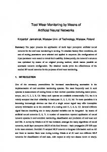
3. Discussion on Force and Vibration Results A typical plot of the force parameters, vibration component and tool wear with respect to machining time, are shown in the Fig.l. All the force components have been found to increase consistently with the deterioration of the sharpness of the cutting edge. The increase in the magnitude of Py may be due to greater
nose wear and auxiliary flank wear, Vs. Large nose wear and auxiliary flank wear also cause increase in Px and Pz, to some extent. The vibration signal does not show a very clear trend in its change with the growth of wear. In general, the vibration signal shows a decreasing nature with growth of tool wear, possibly due to the damping phenomenon. The changes that occured in the force ratios, PxlPz, PxlPy and PyIPxz, with the growth of tool wear(Fig.2) are evident from the correspondending patterns of the cutting force components.
4. Tool Wear Monitoring Using Neural Networks 4.1 Neural Networks Algorithm Appropriate analysis of the signal data is essentially required for achieving high accuracy and reliability of tool wear assessments. The Neural Networks used in the present work have to be trained off-line with a Back Propagation(BP) type learning algorithm and then can be used on-line with the feed-forward method. Neural networks(NN) work through a connectionist model where the input nodes supply weighted values of each node after adding an offset bias(threshold) value to the nodes in the hidden layer, where an activation function is used to determine the value of each node. A similar process is used between the hidden and the output layer. Fig.3 illustrates the basic structure of the NN with a single hidden layer used in the present work. The weights(~) and the threshold values(e) are adjusted until the error value comes within the preset limit, or the preset number of iterations is reached. The activation function f(x) used here is the Sigmoid function which is given by[11]: f(x)
1
=
.... (1)
1 + exp (-x) where:
TABLE 1. Cutting conditions during machining with coated carbide inserts depth Exp cuttlng feed of cut No. velocity So Vr(m/min) mm/rev) t (mIn) 1.5 336 0.2 1 1.5 190 0.1 2 1.5 245 0.14 3 1.5 336 0.1 4 1.5 190 0.2 5 2.0 220 0.16 6 245 1.5 7 0.2
x=L:~u+e
.... (2)
u = input, hidden node values In this investigation, the process has been initialized by assigning random numbers in between ±3 to the weights and biased weight.s. When the RMS error between the target and the output(out) of the process is large, the weights and -bias weights are changed and the outputs are recalculated. The weights are changed using the following steps. For the output layer, error 8... is given by[ 11]: 02
= out
(1- out)
(target- out) .... (3)
Santanu Das et al. / Journal of Materials Processing Technololgy 63 (199?J 187-192
wear(lJm). vibration(m/sec 2 ) and force(N)
189
npu
layer
1400 .--------:-:----=-=:-::---.....--:---;-:-:-~-....., Vc 336 m/min.(hi~h) ....... V. So 0.2 mm/rev.(hlgh) t 1.5 mm Vs eee9€l P 1200 x
Vc
*****
hidden layer
So
~Py
~Pz
1000
+++++ Vibx 100 Px,
800
Pz
600
400 Vib
200
O.......-.--r--r--.---r-...,.--.---.--~
Fig.3. Fig.l.
Growth of flank wear and change in force and vibration parameters
Structure of the neural networks used
and for hidden layer, error 8. is given by: .... (4)
force ratio 2.0
1.8
Vc So t
336 m/min.(hi~h) 0.2 mm/rev.(hlgh) 1.5 mm
LEGEND -------........ px/Pz l*H:HHl
PXI.Pl
~pylpxz
1.6
where v is the hidden node value. Incremental changes in the weights during the Nth iteration, (~(N)) between the nodes of two layers are detennined from the following equation:
1.4 ~w(n)
1.2 1.0 0.8 0.6
0.4 0.2 1 0
machining
Fig.2.
Growth of flank wear and change in force ratios
=n
0 +
~ ~w(N-l)
.... (5)
where ec.is the momentum factor and 11 is the learning rate. All the patterns were suitably normalized[ll] between 0 to 1 to fit the Sigmoid function model. The cutting conditions and the sensor signal parameters have been used as the input to the NN model to estimate the average flank wear(ya) of the turning insert. The learning rates and the momentum factors were varied between 0.06 to 0.15, and 0.07 to 0.15, respectively, to minimize the RMS error during training. The number of hidden nodes were varied from 3 to 8 to explore the minimum error condition with 5,000 iterations. After training the network, the NN model becomes ready to assess the tool wear with the set of data of the input parameters.
Santanu Das et al. / Journal of Materials Processing Technololgy 63 (1997) 187-192
190
4.2 ResuJ.ts and Discussion
After training the network with 42 data patterns, the model is tested 261 times during this work. In the figures from Fig.4(a) to Fig.4(g), plots of directly measured average flank wear, Vb and different NN model estimates are shown with respect to machining time. The model estimates of flank wear show quite close matching with the directly measured Ve values. The small deviations observed at some points may be attributed to the nature of the trained network. Fig. 5 shows clearly the absence of sizeable scatter in the wear estimates, thereby indicating the applicability of the neural network model in assessing the flank wear of the coated carbide inserts in the turning of C60 steels.
flank wear, Va (IJm) 300 Vc 190 m/min.
So 0.1 mm/rev. t 1.5 mm 250-4--------...J
(b)
200
150
100
50
8 0
flank wear, VB ()-1m) 300 Vc 336 m/min.
So : 0.2 mm/rev. t : 1.5 mm 250-+----------1
300
2400
3200
4000
4800
5600
245 m/min.
Vc So t
(a)
1600
0.14 mm/rev 1.5 mm
(e)
250
200
200
150
150
100
100
50 'J
O-?\'--,--r----,--,--,--,--,.....-.---l
0
,. '"
~
LEGEND -------............. measured - - - - NN model 8 0
1600
2400
3200
machining time, second
Fig.q(a-c). Growth of flank wear; measured and model estimates at different cutting conditions
4000
Santanu Das et aL / Journal of Materials Processing Technololgy 63 (1997) 187-192
flank wear, VB (J.lm) 300
191
flank wear, VB (j.Jm)
Vc
336 m/min. So 0.1 mm/rev. t 1.5 mm 250+--------'
300
Vc So t
220 m/min. 0.16 mm/rev 2 mm 250-t-----------J
(d)
200
(f)
200
.,,"----150
100
50
1000 1200 1400 300-r---- -.----:---.-------------, Vc 190 m/min. So 0.2 mm/rev. (e) t 1.5 mm 250-+-----------'
200
0 300
8 0 Vc So t
1600
245 m/min. 0.2 mm/rev. 1.5 mm
(g)
250
200
I
.... ''''_'
150
•
... , ,
I \
, " -."
\ \
150
,
\ I •
I
~"'/
1\
\ \
I
I
I •
100
'.
100
I I~ I
, 50
50
LEGEND --------
I .~I
~E:_~~~_Q
.........- measured ---- NN model 8 0
1600
2400
3200
4000
4800
machining time, second
.........- measured - - - - NN model
o
1200
time, second
Fig.q(d-g). Growth of flank wear; measured and model estimates at different cutting conditions
1600
192
Santanu Das et aL / Journal of Materials Processing Technololgy 63 (1997) 187-192
6. References
Fig.5. Degree of accuracy of tool wear estimation 5. Conclusions The following conclusions can be drawn from the present investigation. 1. The flank wear estimation by the back-propagation type neural networks model with a 8-7-1 structure is in very close agreement with the directly measured value. 2. The estimation error shown by the model is small, so that the model can be used effectively for the on-line assessment of flank wear.
[1] P.M. Lister and G. Barrow, Tool condition monitoring systems, Proc. 26th Int MfDR Con!, Macmillan, London ,(1985) pp.271-288. [2] L. Dan and J. Matthew, Tool wear and failure monitoring techniques for turning- a review, .Tnt J. Mach. Tools Manuj., 30 (1990) 579-598. [3] D.A Dornfeld, In-process recognition of the cutting states, JSME .Tnt J.,37 (1994) 638-650. [4] E. Ernel and Jr. E.K Asibu, Acoustic emission and force sensor fusion for monitoring the cutting process, .Tnt J. Mech. Sci.,31 (1989) 795-809. [5] D.A Dornfeld, Neural network sensor fusion for tool condition monitoring, Annals of CIRP, 42 (1990) 101-105. [6] Y. Yao andX.D. Fang" Modeling of multivariate time series for tool wear estimation in finish-turning, lnt J. Mach. Tools Manuj., 32 (1992) 495-508. [7] S. Das and AB. Chattopadhyay, On-line tool wear monitoring with multiple regression and GbIDH algorithm, ICAlJTO..95, Indore, India (1995) pp.521525. [8] HV. Ravindra, Ph.D. Thesis, nT, Madras, India (1993). [9] P.Y. Chao, P.M. Ferriera and C.R Liu, Applications of GMDH -type modelling in manufacturing, J. Manu! Syst3.,7 (1988) 241-252. [10] S. Das, R Roy and AB. Chattopadhyay, Evaluation of wear ofturning carbide inserts using neural networks, .Tnt J. Mach. Tools Manu!, paper No.- RP2I2104 (in press). [11] RP. Lippmann, An introduction to computing neural nets, IEEE ASSP Mag., (Aprtll987) 4-22. [12] L. Monostori, A step towards intelligent manufacturing: modelling and monitoring of manufacturing process through artificial neural networks, Annals ofCIRP, 42 (1993) 485-488. [13] S.B. Rao, Tool wear monitoring through the dynamics of stable turning, ASME, J. Eng.for Ind., 101 (1986) 183-190.