High Performance AODV Routing Protocol for Hybrid Wireless Mesh Networks Asad Amir Pirzada1, Marius Portmann1,2 1
Queensland Research Laboratory, National ICT Australia Limited, Brisbane, QLD 4000, Australia 2 School of ITEE, The University of Queensland, Brisbane, QLD 4072, Australia E-mail:
[email protected],
[email protected]
Abstract – Hybrid Wireless Mesh Networks are wireless multi-hop networks consisting of two types of nodes, Mesh Routers and Mesh Clients. Mesh Routers are more static and less resource constrained than mobile Mesh Clients, and form the wireless backhaul of the network. Routing in Hybrid Wireless Mesh networks, where both types of nodes participate in the routing and forwarding of packets, is a challenging task. In this paper, we present extensions to the Ad-hoc On-demand Distance Vector (AODV) routing protocol with the aim to exploit the heterogeneity of Hybrid Wireless Mesh Networks. As demonstrated via extensive simulations, our extensions achieve a more than 100% improvement over standard AODV in terms of key performance metrics such as packet loss, goodput and delay. Index Terms – Hybrid, mesh, wireless, network, routing.
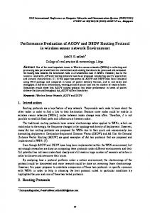
any Mesh Routers. A Client WMN is essentially a pure multi-hop mobile ad-hoc wireless network [2]. A Hybrid WMN combines the connectivity pattern of both the Infrastructure and Client WMNs. In these networks, both the Mesh Clients and Mesh Routers are actively involved in the routing and forwarding of packets. In addition, the Mesh Clients can also access the wireless backhaul network via multiple client hops. A typical scenario where a Hybrid WMN might be employed is in emergency response and disaster recovery situations, where traditional communications infrastructure might not be available. In such a case, a hybrid WMN can provide a so-called incident area network, as illustrated in Figure 1. Mesh-Router
I. INTRODUCTION Wireless Mesh Networks (WMN) have recently gained considerable popularity owing to their self-configuring, self-optimizing and self-healing capabilities. These networks offer an attractive platform for a wide range of applications, such as public safety and emergency response communications, intelligent transportation systems, and community networks. A WMN consists of two types of wireless nodes: Mesh Routers and Mesh Clients. The Mesh Routers have improved computational, communication and power resources as compared to Mesh Clients. Mesh Routers are generally static and form the multi-hop backhaul network with optional access to other auxiliary networks. In addition, Mesh Routers are also typically equipped with multiple wireless network interfaces and are therefore able to establish high capacity connections. Mesh Clients are mobile devices, which take advantage of the existing communication infrastructure provided by the Mesh Routers. WMNs can be divided into three main types [1]: Infrastructure, Client, and Hybrid. In an Infrastructure WMN, Mesh Clients gain access to each other or to the backhaul network through Mesh Routers and are not actively involved in the routing and forwarding of packets. Thus, all Mesh Clients gain access to Mesh Routers via a single wireless hop. In Client WMNs, Mesh Clients communicate with each other directly, without involving
INCIDENT AREA NETWORK Mesh-Router
Mesh-Client
Mesh-Client
Figure 1: Hybrid Wireless Mesh Network
There are two major challenges associated with multi-hop communication in a Hybrid WMN. The first problem is due to the shared wireless medium (Physical/M AC layer), while the second problem is associated with the discovery of optimal routes in a highly dynamic network (Network layer). Hybrid WMNs commonly adopt the IEEE 802.11 standard [3] at the Physical and MAC layers. In general, IEEE 802.11 wireless transceivers only offer a half-duplex communication mode, i.e. they can either transmit or receive, but not both at the same time. Packets are
transmitted using the un-slotted Carrier Sense Multiple Access scheme with Collision Avoidance (CSMA/CA). In CSMA/CA each transmitting node waits for a vacant channel by sensing the medium. If the channel is vacant, it makes the transmission. In case the transmission is successful, it is acknowledged to by the recipient [4]. For single-hop communication the CSMA/CA scheme is considered adequate and offers efficient use of the frequency spectrum. However, for multi-hop communication the performance of the CSMA/CA scheme degrades significantly with increasing number of hops [5]. One of the problems is that CSMA/CA based interfaces are half-duplex and cannot support simultaneous sending and receiving of data. Another performance limiting factor in WMNs is co-channel interference, where nodes within interference range are transmitting simultaneously on the same channel, resulting in collisions, reduced throughput and increased communication delays. Routing in a multi-hop wireless mobile network is a challenging task. In contrast to the relatively static Mesh Routers, Mesh Clients can be highly mobile, resulting in routes frequently being severed. In addition, as Mesh Clients are relatively resource constrained devices, the routes should preferably be established via Mesh Routers. Consequently, the type of nodes, i.e. Mesh Client versus Mesh Router, should be taken into consideration during the route establishment process. The routing protocols used for Hybrid WMNs can be broadly categorized into two types: Reactive and Proactive. In reactive routing protocols, the routes are established only when required, generally via flooding of Route Request packets in the network. While, in proactive routing protocols the routes are established before actual usage, through periodical exchanges of connectivity information. Both protocols have their individual advantages. Reactive protocols focus on minimizing control packet overhead while the proactive protocols attempt to minimize the route establishment delays. The Ad-hoc On-demand Distance Vector (AODV) protocol is one of the most commonly used reactive routing protocols. AODV was originally developed for homogenous mobile ad-hoc networks, where nodes have comparable computational and communication resources. Thus, WMNs that employ standard AODV, including commercially supported products [6], are unable to exploit the heterogeneity in the network, especially in Hybrid WMNs In this paper, we present a variant of the AODV protocol that effectively mitigates the problems and limitations associated with the Physical, MAC and Network layers in Hybrid WMNs. One of our key contributions is the introduction of a new routing metric that allows differentiating between node types (Mesh Routers and Mesh Clients). The effect of this new metric is that routes preferentially include Mesh Routers and only involve Mesh Clients when absolutely necessary. We further incorporate a
mechanism in the route discovery process that, on nodes equipped with multiple network interfaces (radios), allows selecting the interface that results in the highest capacity and the least amount of interference. With the help of extensive simulations, we show that our variant of AODV outperforms standard AODV by a considerable margin. The remainder of the paper is organised as follows. We first discuss some relevant related work in Section 2. The high performance AODV protocol is then explained in Section 3. Simulation results and their corresponding analysis is presented in Section 4, with concluding remarks in Section 5. II. RELATED WORK Hyacinth [7] is a multi-channel static wireless mesh network protocol that uses multiple radios and channels to improve the network performance. It supports a fully distributed channel assignment algorithm, which can dynamically adapt to varying traffic loads. Hyacinth’s channel assignment algorithm breaks a single-channel collision domain into multiple collision domains, each operating on a different frequency. Nodes control and coordinate allocation of channels to interfaces via periodic exchange of messages containing channel usage status. Using the per-channel total load information a node can issue a change channel message to its neighbour in order to switch to a less utilised channel. The Multi-Channel Routing Protocol (MCRP) [8] is a routing protocol specifically designed for networks with single-radio nodes, which support a channel switching delay of 80 µs or less [9]. The protocol assigns channels to data flows rather than assigning channels to interfaces. This implies that all nodes supporting a flow have to be on a common channel. The advantage of this mechanism is that once the route is established, nodes are not required to switch channels for the duration of the flow. The Multi-Radio Link Quality Source Routing (MRLQSR) [10] protocol has been developed for static community wireless networks. The protocol identifies all nodes in the wireless mesh network and assigns weights to all possible links. The link information including channel assignment, bandwidth and loss rates are propagated to all nodes in the network. The Expected Transmission Time (ETT) on each link is computed using the Expected Transmission Count (ETX), bandwidth and packet loss. The ETT metric is further used to compute the Weighted Cumulative Expected Transmission Time (WCETT), which defines the path metric designed for multi-radio WMNs. The Multi-Channel Routing (MCR) protocol [11] has been developed for dynamic, multi-radio WMNs. The protocol makes use of an interface switching mechanism to assign interfaces to channels. Two types of interfaces are assumed: fixed and switchable. Switching is carried out depending upon the maximum number of data packets queued for a single channel. The switching mechanism assists the MCR protocol in finding routes over multiple
channels. MCR uses a new routing metric, which is computed as a function of channel diversity, interface switching cost and hop-counts. The diversity cost is assigned according to the least number of channels used in a route. Thus, a route with a larger number of distinct channels in a route is considered to be having a lower diversity cost. The switching cost is used to minimize the frequent switching of wireless interfaces. The related work discusses various switching mechanisms, which can be used to improve the routing performance of a network. However the accurate execution of these mechanisms in a mobile network entails the availability of a virtual switching protocol and incurs switching delays [10, 12]. In contrast, we consider a network where channels are statically allocated to interfaces. In addition, none of related works differentiate between the type of network nodes (Mesh Routers and Mesh Clients) in Hybrid WMNs. III. HIGH PERFORMANCE AD-HOC ON-DEMAND DISTANCE VECTOR ROUTING PROTOCOL (AODV-HP) The AODV routing protocol is a reactive distance vector routing protocol that has been optimised for mobile ad-hoc wireless networks [13]. AODV borrows basic route establishment and maintenance mechanisms from the Dynamic Source Routing (DSR) [14] protocol, and hop-tohop routing vectors from the Destination-Sequenced Distance-Vector (DSDV) routing protocol [15]. To avoid the problem of routing loops, AODV makes extensive use of sequence numbers in control packets. When a source node intends to communicate with a destination node whose route is not known, it broadcasts a Route Request packet (RREQ). Each RREQ contains an ID; source and the destination node IP addresses and sequence numbers together with a hop-count and control flags. The ID field uniquely identifies the RREQ. The sequence numbers indicate the freshness of control packets, and the hop-count maintains the number of nodes between the source and the destination. Each recipient of the RREQ that has not seen the Source IP and RREQ ID pair, or does not maintain a fresher (with larger sequence number) route to the destination, rebroadcasts the same packet after incrementing the hop-count. Such intermediate nodes also create a Reverse Route to the source node for a certain interval of time. When the RREQ reaches the destination node, or any node that has a fresher route to the destination, a Route Reply packet (RREP) is generated and unicast back to the source of the RREQ. Each RREP contains the destination sequence number, the source and the destination IP addresses, route lifetime together with a hop-count and control flags. Each intermediate node that receives the RREP, increments the hop-count, establishes a Forward Route to the source of the packet and transmits the packet on the Reverse Route. In case a link break is detected for a next hop of an active route, a Route Error packet (RERR) is
sent to its active neighbours that were using that particular route. When using AODV on a node with multiple radios, each RREQ is broadcast on all the node’s interfaces. In order to avoid broadcast storms, a random delay is added in the transmission of each RREQ. Intermediate nodes with one or more interfaces operating on a common channel, receive the RREQ and create a Reverse Route that points towards the source node. If the RREQ is a duplicate, it is simply discarded. The first RREQ received by the destination, or any intermediary node, is selected and all subsequent RREQs are discarded. The RREP is generated in response to the selected RREQ, and is sent back to the source node via the existing Reverse Route. Our protocol variant (AODV-HP), adds two simple modifications to AODV. In the first modification, we use the (Hop Count) – (Mesh Router Count) as the routing metric instead of the standard hop count, to facilitate preferential routing of packets via Mesh Routers. By selecting routes which minimize this metric, we can guarantee that that the established routes primarily consist of Mesh Routers. We use 4 bits of the reserved AODV header to include a Mesh Router count variable, which is incremented every time a RREQ packet is forwarded by a Mesh Router. Our second modification to AODV maximises the channel diversity of paths, which comprise of multi-radio nodes. In this case, multiple links can exist between neighbouring nodes. The choice of link (interface) to use between two nodes will not affect the routing metric, and we need some other method to select the best link. In our protocol, nodes forwarding a RREQ packet also recommend a channel, which is subsequently used to communicate with the next hop. In order to minimise cochannel interference, nodes recommend least loaded channels for next hop communication. If a hop shares multiple channels with the sender of the RREQ packet, it will receive multiple copies of it. If possible, the node will create a Reverse Route via the recommended channel (interface). We use the remaining 7 reserved bits in the AODV header to convey the recommended channel information to the next hop. The route establishment and optimization process is shown in Fig. 2. When a source node needs to discover a route, it first executes the Route Optimization Function (ROF). The ROF first scans the existing routing tables and finds the interfaces which are not being used in any of the active data connections. In case none of the interfaces is free, it examines the Network Interface Queue (IFQ) of each interface. The IFQ is a drop-tail FIFO buffer, established between the Link and MAC layers, and holds packets which are to be transmitted on to the Physical Layer. The IFQ length gives the current number of the packets, which are awaiting transmission. The prime advantage of using IFQ lengths is that it automatically takes into consideration the channel
interference levels and traffic loads for both intra-flow and inter-flow data connections. All interfaces, which have an IFQ length below a certain threshold, are selected as possible candidates for the Optimal Channel selection. The channel information of these free or least loaded interfaces is then retrieved through a Physical Layer hook. A random channel is then selected out of the free or least loaded channels, which is called the Optimal Channel. By randomizing the Optimal Channel, we maximize the channel distribution in two or more adjacent flows. The ROF returns this channel to the calling function. The source node recommends this Optimal Channel in the RREQ packet and broadcasts it over all available interfaces. Source Node
Destination/Intermediate Node
Start
Start
Need Route to Destination
Receive RREQ
Route Optimizer
N Route Optimizer
Interface = Rec Channel ?
N
Am I the Destination ?
Recommend Channel in the RREQ
Y Start RREQ Timer
Send RREQ on all interfaces
Create Reverse Route on Channel
Buffer RREQ
End Route Optimizer RREQ Timer Expired ?
Route Optimizing Routine Route Optimizer Recommend Channel in the RREQ
Scan Routing Table
Are any channels free ?
N
Y
Find least loaded channels
Y Select Max (Mesh Router Count) RREQ
Mesh Router Count ++
Create Reverse Route on Rec Channel
Send RREQ on all interfaces
Randomize Channels Return Channel
N
Send RREP on Rec Chan Interface
End
Fig 2: Route Establishment and Optimization
Each intermediate node receiving the RREQ packet first verifies whether one of its interfaces is operating on the Recommended Channel. If this is the case, it creates the Reverse Route using this interface. In case the intermediate node has no interface operating on the Recommended Channel, it finds an Optimal Channel from the received RREQ packets and creates the Reverse Route on it. It then executes the ROF again to find the Optimal Channel to be recommended in the RREQ to the next hop neighbour. In case the intermediate node is a Mesh Router, it increments the Mesh Router Count. The intermediate node then broadcasts the RREQ on all interfaces. In case the RREQ is received by the destination node, it starts a RREQ Timer. The period of the RREQ Timer can be dynamically adjusted and essentially represents the maximum amount of time a node is willing to wait before replying to the most optimal RREQ. We set this value to 100 ms or 5 RREQ packets, which ever is achieved earlier. During this time the destination nodes keeps receiving
RREQs and stores them in a buffer. When the timer expires, the optimal RREQ according to our routing metric is selected and a Reverse Route is created. A Route Reply packet is then sent back to the source node via the Reverse Route established using the above mentioned optimizations. The final route created in this manner provides optimized channel diversity and guarantees preferential involvement of Mesh Routers. IV. SIMULATION RESULTS AND ANALYSIS A.
Simulation Environment
We have evaluated the efficiency of the AODV-HP protocol through extensive simulations in NS-2 [16], using the Extended Network Simulator (ENS) extensions [17]. A WMN covering an area of 1 square km is established using 25 static Mesh Routers, which are distributed in a uniform 5x5 grid and each equipped with three 802.11b radios. The network further consists of 50 mobile Mesh Clients, equipped with a single radio and placed randomly in the simulation area. Concurrent UDP flows are established between 30 randomly selected source and destination Mesh Client pairs. The performance metrics are obtained by ensemble averaging [18] the results from over 50 simulation runs. The simulation parameters are listed in Table 1. TABLE 1: SIMULATION PARAMETERS Examined Protocols Simulation time Simulation area Propagation model Mobility model for Mesh Clients Speed of Mesh Clients Transmission range Packet Size Packet Rate Number of 802.11b radios in Mesh Clients Number of 802.11b radios in Mesh Routers
AODV and AODV-HP 900 seconds 1000 x 1000 m Two-ray Ground Reflection Random waypoint 0, 5, 10, 15 & 20 m/s 250 m 512 bytes 32 pkts/sec 1 3
B. Simulation Metrics The simulations provide the following performance metrics: Packets Lost: The n umber of packets that were lost due to unavailable or incorrect routes, MAC layer collisions or through the saturation of interface queues [19]. Aggregate Good put: The total number of application layer data bits successfully transmitted in the network per second. Packet Delivery Percentage: The ratio between the number of data packets successfully received by destination nodes and the total number of data packets sent by source nodes. Routing Packet Overhead: The ratio of control packets to successfully received data packets. Average Latency: The mean time (in seconds) taken by the data packets to reach their respective destinations. Path Optimality: The ratio between the length (number of hops) of the shortest possible path and the actual path taken by the data packets.
6
5
x 10
x 10
4
8 Tx−Pkts AODV AODV−HP
7
90 Tx−Rate AODV AODV−HP
3.5
AODV AODV−HP 80
Aggregate Goodput (bps)
6
Packets Lost
5
4
3
Packet Delivery %age
3
2.5
2
1.5
2
1
1
0.5
70
60
50
40
0
0 0
5
10 Maximum Speed
15
20
8
0
5
10 Maximum Speed
15
30
20
0
5
10 Maximum Speed
15
0.8
0.45
AODV AODV−HP
0.78 7
0.4
6
0.35
20
AODV AODV−HP 4
3
0.74
Path Optimality
5
Average Latency (seconds)
Routing Packet Overhead
0.76
0.3
0.25
0.72 0.7 0.68
0.2 0.66
2
0.15 0.64
AODV AODV−HP 1
0
5
10 Maximum Speed
15
20
0.1
0.62 0
5
10 Maximum Speed
15
20
0
5
10 Maximum Speed
15
20
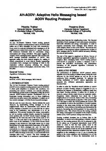
Fig 3: Simulation Results
C. Results and Analysis The simulation results are shown in Fig. 3, for a range of maximum client speeds. The results indicate that AODVHP is able to significantly reduce the packet loss compared to standard AODV. During route establishment, AODV-HP focuses on engaging minimally loaded channels for routing data traffic. This helps to sustain the thirty simultaneous 128 kbps connections. However, standard AODV forms routes over multiple hops by randomly selecting the available channels. Thus, a route may be comprised of a large number overlapping and saturated channels, resulting in severe packet losses. The lower packet losses incurred by AODV-HP enable it to achieve a higher aggregate goodput. For a total offered network load of approximately 3.5 Mbps, AODV-HP successfully achieves a goodput of more than 3 Mbps. The standard AODV protocol, due to a high packet loss, is unable to achieve a goodput of more than 1.5 Mbps with increasing client speeds. The packet delivery rate of AODV-HP drops from 87% to almost 83% when the maximum client speed is increases from zero to 20 m/s. The
packet delivery of standard AODV drops from 46% to 40% for a similar increase in client speeds. As mentioned earlier, the standard AODV protocol forms routes using random channels rather than selecting optimal channels available in the network. As a result, links frequently get saturated and suffer from interference. This essentially causes the routes to sever, thereby causing new route discoveries. These route discoveries increase the routing overhead to almost seven control packets for each data packet. On the other hand, AODV-HP selects optimal channels during the route establishment phase. This enables the route to be effective for longer durations, which minimizes the need for extraneous route discoveries. As the routes created by the AODV-HP have been optimized for minimal interference and optimal load distribution among parallel links, packets are sent promptly without incurring excessive contention for the physical medium. This has the effect of reduced average latency of the data packets traversing an average of four hops. The packets flowing on routes established using AODV face severe contention for the physical medium and are hence
significantly delayed at each hop. The path optimality of the AODV-HP also remains higher than the standard AODV protocol, due to the establishment of consistent routes during the route discovery process. V. CONCLUSIONS Hybrid Wireless Mesh Networks are composed of static Mesh Routers and mobile Mesh Clients. The Mesh Routers have significantly higher computation and communication resources in comparison to the Mesh Clients. However, currently employed routing protocols do not discriminate between the two types of nodes, and hence suboptimal routing takes place. In this paper, we have presented AODV-HP, a variant of the AODV protocol, which makes effective use of the additional capabilities offered by the Mesh Routers. Our simple modifications result in a significant improvement of the key performance metrics evaluated for Hybrid WMNs. The simulation results show that under high mobility and traffic load conditions, AODV-HP provides an improvement of more than 100% in terms of packet delivery rate, latency and routing overhead over the standard AODV routing protocol.
[9]
[10]
[11]
[12]
ACKNOWLEDGEMENTS National ICT Australia is funded by the Australian Government's Department of Communications, Information Technology, and the Arts and the Australian Research Council through Backing Australia's Ability and the ICT Research Centre of Excellence programs and the Queensland Government. REFERENCES [1]
[2]
[3]
[4] [5]
[6] [7]
[8]
I. F. Akyildiz and X. Wang, "A Survey on Wireless Mesh Networks," IEEE Communications Magazine, vol. 43, pp. S23-S30, 2005. A. A. Pirzada and C. McDonald, "Establishing Trust in Pure Ad-hoc Networks," presented at Proceedings of the 27th Australasian Computer Science Conference (ACSC), 2004. IEEE, "Wireless LAN Medium Access Control (MAC) and Physical Layer (PHY) Specifications 802.11," 1997. A. S. Tanenbaum, Computer Networks, Fourth ed: Prentice Hall, 2002. P. Gupta and P. R. Kumar, "The Capacity of Wireless Networks," IEEE Transactions on Information Theory,, vol. 46, pp. 388-404, 2000. "Locust World," http://www.locustworld.com/, 2002. A. Raniwala and T. C. Chiueh, "Architecture and Algorithms for an IEEE 802.11-based Multi-Channel Wireless Mesh Network," presented at Proceedings of the 24th Annual Joint Conference of the IEEE Computer and Communications Societies (INFOCOM), 2005. J. So and N. H. Vaidya, "A Routing Protocol for Utilizing Multiple Channels in Multi-Hop Wireless
[13]
[14]
[15]
[16] [17]
[18]
[19]
Networks with a Single Transceiver," Dept. of Computer Science and Coordinated Science Laboratory, University of Illinois at UrbanaChampaign, Technical Report 2004. P. Kyasanur and N. H. Vaidya, "Routing and Interface Assignment in Multi-Channel MultiInterface Wireless Networks," presented at Proceedings of the IEEE Wireless Communications and Networking Conference, 2005. R. Draves, J. Padhye, and B. Zill "Routing in MultiRadio, Multi-Hop Wireless Mesh Networks," presented at Proceedings of the 10th Annual International Conference on Mobile Computing and Networking, 2004. P. Kyasanur and N. H. Vaidya, "Routing and Linklayer Protocols for Multi-Channel Multi-Interface Ad Hoc Wireless Networks," SIGMOBILE Mobile Computing and Communications Review, vol. 10, pp. 31-43, 2006. R. Chandra and P. Bahl, "MultiNet: Connecting to Multiple IEEE 802.11 Networks using a Single Wireless Card," presented at Twenty-third Annual Joint Conference of the IEEE Computer and Communications Societies (INFOCOM), 2004. J. Broch, D. A. Maltz, D. B. Johnson, Y. C. Hu, and J. Jetcheva, "A Performance Comparison of Multihop Wireless Ad hoc Network Routing Protocols," presented at Proceedings of the 4th Annual International Conference on Mobile Computing and Networking (MobiCom), 1998. D. B. Johnson, D. A. Maltz, and Y. Hu, "The Dynamic Source Routing Protocol for Mobile Ad hoc Networks (DSR)," IETF MANET, Internet Draft, 2003. C. E. Perkins and P. Bhagwat, "Highly Dynamic Destination-Sequenced Distance-Vector Routing (DSDV) for Mobile Computers," presented at Proceedings of the SIGCOMM Conference on Communications, Architectures, Protocols and Applications, 1994. NS, "The Network Simulator," http://www.isi.edu/nsnam/ns/, 1989. B. Raman and C. Chebrolu, "Design and Evaluation of a new MAC Protocol for Long-Distance 802.11 Mesh Networks," presented at Proceedings of the 11th Annual International Conference on Mobile Computing and Networking (MobiCom), 2005. W. H. Yuen and R. D. Yates, "Inter-relationships of Performance Metrics and System Parameters in Mobile Ad hoc Networks," presented at Proceedings of the IEEE Military Communications Conference (MILCOM), 2002. A. A. Pirzada, C. McDonald, and A. Datta, "Performance Comparison of Trust-Based Reactive Routing Protocols," IEEE Transactions on Mobile Computing, vol. 5, pp. 695-710, 2006.