State of California MICRO program. .... As a result, the micro rollback ca- pability can be ..... N. R. Saxena is with Hewlett-Packard, Cupertino, CA 95014.
548
IEEE TRANSACTIONS ON COMPUTERS, VOL. 39, NO. 4, APRIL 1990
TABLE VI1 TESTGENERATION FOR SEQUENTIAL BENCHMARK CIRCUITS WITH PARTIAL SCAN
Name S400 S713 S5378 S9234
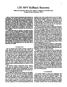
DATA SCANIN
MUX
MASTER LATCH
1 I
FFs 21 19 179 228
1
I
No.
%
9 7 32 53
42.86 36.84 17.89 23.25
1
Vectors 107 83 2612 3458
SLAVE LATCH
I I
Tested
Redundant
Total
98.11 90.71 93.38 43.23
1.89 9.29 6.32 55.80
10000 100.00 99.70 99.04
I
I
(VAX 8650) 7 18 1253 6208
V. D. Agrawal, K. T. Cheng, D. D. Johnson, and T. Lin, “Designing circuits with partial scan,” IEEE Design Test Comput., vol. 5 , pp. 8-15, Apr. 1988. A. D. Friedman and P. R. Menon, Theory and Design of Switching Circuits. Rockville, MD: Computer Science Press, 197.5. A. Miczo, Digital Logic Testing and Simulation. New York: Harper and Row, 1986. W. T. Cheng, “The BACK algorithm for sequential test generation,” in Proc. Int. Conf. Comput. Design (ICCD-88),Rye Brook, NY, Oct. 1988, pp. 66-69. R. V. Hudli and S . C. Seth, “Testability analysis of synchronous sequential circuits based on structure data,” in Proc. Int. Test Conf., Aug. 1989, pp. 364-372. V. D. Agrawal, S. K. Jain, and D. M. Singer, “Automation in design for testability,” in Proc. Custom Integrated Circuits Conf., Rochester, NY, May 1984, pp. 1.59-163. A. V. Aho, J . E. Hopcroft, and J. D. Ullman, The Design and Analysis of Computer Algorithms. Reading, MA: Addison-Wesley, 1974, ch. 10. F. Brglez, D. Bryan, and K. Kozminski, “Combinational profile of sequential benchmark circuits,” in Proc. Int. Symp. Circuits Syst., May 1989, pp. 1929-1934. K. T. Cheng and V. D. Agrawal, “Concurrent test generation and design for testability,” in Proc. Int. Symp. Circuits Syst., May 1989, pp. 1935-1938. E. B. Eichelberger and T. W. Williams, “A logic design structure for LSI testability,” J. Des. Automat. Fault Tolerant Comput., vol. 2, pp. 165-178, May 1978. M. R. Mercer and V. D. Agrawal, “A novel clocking technique for VLSI circuit testability,” IEEE J . Solid-State Circuits, vol. SC-19, pp. 207-212, Apr. 1984.
MoD
CLOCK
Fig. 5 . Scan flip-flop for single clock design.
scan design, the overhead in partial scan design is thus reduced in direct proportion to the fraction of flip-flops that are scanned. An alternative design practice, however, uses a single clock signal. Either a master-slave operation is achieved by using two latches that are sensitive to different levels of the clock signal, or simply edgetriggered latches are used. For scan design, flip-flops are preceded by multiplexers to switch between the normal signal and the scan signal [7]. All multiplexers are controlled by a mode control signal that is added to the circuit. In this design, the same clock signal is used for both normal and scan functions. In a partial scan circuit, the unscanned latches must hold their normal states while data are being scanned in. One way to accomplish this is to use an additional clock pin feeding only the scanned flip-flops. In the normal mode, both clock pins will carry the same signal. In the scan mode, the clock signal is applied only to the second clock pin. Thus, in addition to the other signals needed for a complete scan design, the partial scan design may need one extra clock pin. The extra clock pin can be eliminated if the scan flip-flop, shown in Fig. 5, is used. The two signals, MODE and CLOCK, are routed to all scanned flip-flops. The same CLOCK signal is routed to all unscanned flip-flops. Signal waveforms for the two modes are easily derived. Assume that the latches in Fig. 5 are active when their clock input is high. Also, the multiplexer selects DATA when its control signal is low, otherwise it selects SCANIN. In the normal mode, MODE is held low and CLOCK carries a periodic high (master active) and low High-Performance Fault-Tolerant VLSI Systems Using Micro (slave active) signal. Thus, DATA inputs are clocked in all flipRollback flops. In the scan mode, CLOCK is held low. Thus, all unscanned flip-flops, that do not receive MODE, are unaffected. For scanned YUVAL TAMIR AND MARC TREMBLAY flip-flops, MODE now carries a clock-like (periodic high and low) signal which activates their master and slave latches. Also, when the Abstract-A key to achieving a high degree of fault tolerance is the master latch is active, that is, MODE is high, SCANIN is selected by the multiplexer. In this design, the need for any additional clock ability to detect errors as soon as they occur and prevent erroneous information from spreading throughout the system. In highly reliable pin is eliminated [12]. systems, this is usually accomplished by checkers and isolation circuits CONCLUSION We have shown that the cyclic structure of a synchronous sequential circuit is mainly responsible for the difficulty of test generation. Partial scan design that breaks up the cycles significantly improves the performance of a sequential circuit test generator. We were able to generate all tests completely automatically for a complex sequential circuit by scanning just 5% of all flip-flops. Beside achieving a low overhead, this partial scan concept is more attractive for two other reasons: 1) the selection of scan flip-flops does not rely on testability measures but directly reduces the circuit complexity for the test generator, and 2) the reliance on functional vectors, that may not always be available, is eliminated. REFERENCES [l] E. Trischler, “Incomplete scan path with an automatic test generation methodology,” in Proc. Int. Test Conf., Nov. 1980, pp. 153-162.
in the communication paths from each module to the rest of the system. This additional circuitry reduces performance by requiring either longer clock cycles or additional pipeline stages. We present a technique, calledrnicro rollback, which allows most of the performance penalty for concurrent error detection to be eliminated. Detection is performed in pmllel with the transmission of information between modules, thus
Manuscript received July 13, 1989; revised November 20, 1989. This work was sponsored by the SDI0 Innovative Science and Technology Office, managed by the Office of Naval Research, contracted to the Jet Propulsion Laboratory under task plan 80-2984; and by Hughes Aircraft Company and the State of California MICRO program. M. Tremblay is supported by an IBM fellowship. The authors are with the Department of Computer Science, University of California, Los Angeles, CA 90024. IEEE Log Number 8933874.
OO18-9340/90/04OO-0548$01.OO
0 1990 IEEE
549
IEEE TRANSACTIONS ON COMPUTERS, VOL. 39, NO. 4, APRIL 1990
removing the delay for detection from the critical path. Erroneous information may thus reach its destination module several clock cycles before an error indication. Operations performed on this erroneous information are “undone” using a hardware mechanism for fast rollback of a few cycles. We discuss the implementation of a VLSI processor capable of micro rollback as well as several critical issues related to its use in a complete system.
Index Terms- Concurrent error detection, error detection latency, fault-tolerant architectures, high-performance processors, rollback, VLSI implementation, VLSI systems.
I. INTRODUCTION In order to achieve fault tolerance, highly reliable systems often require the ability to detect errors as soon as they occur and prevent the spread of erroneous information throughout the system. In some environments (e.g., with high levels of radiation) a high rate of transient faults is expected and system components must be able to recover from (correct) the majority of the resulting errors without resorting to expensive software-driven rollback and reconfiguration. In order to meet these requirements, checkers, error-correction circuitry, and/or isolation circuits are connected in the communication paths between each module and the rest of the system. Information transfers between modules in the system are delayed by the need to wait for checks or possible correction to complete. This results in lower system performance due to increased clock cycle time or additional pipeline stages. The delays due to concurrent error detection and correction can be minimized if these operations are performed in parallel with intermodule communication. Thus, each module processes its inputs immediately when they become available [9]. While this technique largely solves the problem of checking delays, it introduces a new problem in recovery. The state of the system may be “polluted” by erroneous information before an error signal arrives. This will necessitate backing up processing to the state that existed just before the error first occurred, thus returning the system to an error-free state where the offending operation can be retried (or correction may be attempted by other means, such as restoring information from a redundant module). We call the process of backing up a system several cycles in response to a delayed error signal micro rollback [9]. In order to support micro rollback, each module in the system must store all the information necessary to undo the state changes that have occurred in the last few cycles. Straightforward implementation of micro rollback will require significant performance and chip area overheads for replicating all the storage elements in each module. This paper discusses techniques for efficient implementation of micro rollback in VLSI systems. It focuses on the micro architecture and VLSI implementation of a VLSI RISC processor that is capable of micro rollback. We show how the updated state of the entire processor can be checkpointed after every cycle without replicating all the storage. The VLSI implementation of the basic building blocks needed for micro rollback is discussed. Based on VLSI layout and circuit simulation of key modules, it is shown that the micro rollback functionality can be added with only a small performance penalty and with a low area penalty relative to the size of the entire chip. We show how the concept of micro rollback can be used throughout the system, discuss the requirements from modules other than the processor, and show how the various modules operate in a multiprocessor system.
rr. MICROROLLBACK A micro rollback of a module (subsystem) consists of bringing the module back a few cycles to a state that it had reached in the past. In order to be able to perform such an operation, it is necessary to save a “snapshot” of the state of the subsystem (checkpoint) at each cycle boundary [4]. Micro rollback restores the state of a subsystem by overwriting the current state with a “snapshot” taken in the past (see Fig. 1). The number of cycles that can be undone-the rollback
Micro Rollback
L
J
I
I
cycle 11 cycle 12 c y d e 13 cycle 14 cycle 15 cycle 16 cycle 17
550 A key novel aspect of our work is the idea of hardware-supported checkpointing and rollback specifically aimed at allowing use of relatively slow error detection and/or correction techniques without loss in system performance. At the micro architecture level, the technique we present for micro rollback of the register file has some similarities with schemes for precise interrupts in high-performance processors [8], [4]. For precise interrupts there is a need to undo state changes that were completed “out of order” so that the system can be returned to a precise macro instruction boundary. Micro rollback is inherently simpler-there is no need to keep track of instruction boundaries since the rollback event is transparent to the software. Many of the proposed schemes for precise interrupts require multicycle rollback, increased bandwidth to storage elements, or complex control. The technique we propose in Subsection IV-A is similar to the reorder buffer with bypasses [8] and forward difference [4] schemes. As shown in Subsection IV-A, our technique does not require the extra bus or the complex control that a reorder buffer needs for manipulating its head and tail registers and performing rollback. Our technique for the register file is similar to the forward difference scheme [4] but since [4] does not provide implementation details, a useful comparison cannot be presented. Some fault-tolerant processors attempt to recover from transient faults using instruction retry [2]. When an error is signaled, the system rolls back to the most recent macro instruction boundary and the instruction stream is restarted from there. Micro rollback is a generalization of instruction retry. The two schemes differ in that micro rollback is performed at a lower level-on the basis of clock cycles rather than instructions. This allows rollback to be executed at the logic level, without keeping track of instruction semantics and instruction pipeline conditions. As a result, the micro rollback capability can be independently implemented in each module of a synchronous system, regardless of its function, by following very simple specifications- it must be possible to roll back all storage elements by any number of cycles up to a specified limit. Building blocks which are capable of micro rollback can be interconnected in arbitrary ways to construct systems capable of micro rollback. Such flexibility is difficult to achieve if the semantics of rollback are tightly coupled to the specific function of each module. Micro rollback is specifically aimed at efficient, high-performance VLSI implementation. Any meaningful evaluation of this technique must take into account the associated area and performance overheads- it is not useful to eliminate delays due to error detection latency at the cost of reduced performance for all system operations. In a VLSI chip, performance is critically dependent on such details as bus length, bus load, control complexity, routing of control signals, etc. Thus, an evaluation of a technique such as micro rollback cannot be done based on algorithms and block diagrams alone.
IEEE TRANSACTIONS ON COMPUTERS, VOL. 39, NO. 4, APRIL 1990
DWB Register File
.
L Decoder
FIFO
Priority Circuit
write I
I
Register Addresses
CAM
Fig. 2. A register file with support for micro rollback.
and the method used to roll back in one cycle are described below. The state to be saved and restored is located in the register file and the individual state registers.
A . Support f o r Micro Rollback in the Register File
At every cycle, a write into the register file may be performed. As discussed above, it is impractical to preserve the state of the file for N cycles by replicating it N times due to the area and performance overheads. We propose an alternative method which minimizes the extra hardware while still allowing a rollback of up to N cycles to be executed in one cycle [9]. I) High -Level Description: Whenever the processor writes data to one of its registers, the address of the destination register and its new contents are stored in an N-word FIFO buffer, which we call a delayed write buffer-DWB (Fig. 2). The register address is held in a content-addressable memory (CAM) and the memory cells holding both the data and address can be shifted. During the register read phase of every instruction, the register addresses of the two operands are compared with the addresses of the registers stored in the DWB. If there is a match and the valid bit in the CAM is set, the data of the matching register are gated on to the corresponding internal data bus. If there is more than one match for a particular operand, a priority circuit is used to provide the most recent version available in the DWB. This corresponds to the rightmost valid register in the FIFO in Fig. 2. The DWB delays each write by Ncycles before it is finally written into the register file. During every cycle, a new entry is made in the rightmost cell of the DWB. If a write occurs, the data are entered and the DWB position is marked valid. If no write occurs, the DWB word is reserved but marked as invalid. During every cycle, the oldest IV. SUPPORT FOR MICRO ROLLBACK IN A VLSI RISC PROCESSOR (leftmost) entry in the DWB is written to its corresponding address Efficient techniques for supporting micro rollback in the modules in the register file if its valid bit is set, and discarded otherwise. In of VLSI systems are necessary for realizing its potential to achieve order to roll back p cycles (1 5 p 5 N ) , the last p entries in the both high performance and high reliability. For example, a possible DWB (the rightmost p entries in Fig. 2) are invalidated by clearing approach to supporting micro rollback with a rollback range of N the valid bits (no data transfers are needed). An important feature cycles in a conventional processor is based on replicating the register of this design is that during both register read and register write file N times. However, this would result in large overhead in both operations the register file and the DWB operate in parallel without chip area (additional storage cells) and performance (longer buses, significant conflicts for the use of the internal buses (which would larger decoders, etc). lead to additional delays). Our research involves the development of techniques for efficient 2) Implementation and Interfacing of the Register File and support for micro rollback. Through full VLSI layouts of the key DWB: As in RISC 11, the datapath includes a large register file building blocks, we are able to accurately evaluate the chip area consisting of 128 32-bit registers, organized in eight overlapping overhead of our techniques. Our VLSI implementations are all in register banks. The ram cell used in this register file allows two CMOS technology, using the MOSIS scalable design rules (SCMOS). simultaneous reads and one write during a processor cycle. Detailed SPICE simulations of the circuits are used to determine the The top section of the DWB contains the data to be written into performance overhead. These simulations use circuits extracted from the register file, while the bottom part contains the register addresses the layouts, for a 2 pm (A = 1) process. of the corresponding data. The data part is a FIFO which is also a As a concrete example, we are designing and implementing a VLSI RAM so that each register, in addition of shifting to the left, is also processor, based on the Berkeley RISC I1 processor [ 7 ] , capable of accessible from the bus. The bottom part is a FIFO which is also a micro rollback. The process of saving the state of a RISC processor CAM. Each FIFOKAM cell consists of a one-bit static shift-register
55 1
IEEE TRANSACTIONS ON COMPUTERS, VOL. 39, NO. 4, APRIL 1990 30
a m i