382
IEEE TRANSACTIONS ON AUTOMATION SCIENCE AND ENGINEERING, VOL. 13, NO. 1, JANUARY 2016
High Precision Automatic Assembly Based on Microscopic Vision and Force Information Song Liu, De Xu, Senior Member, IEEE, Dapeng Zhang, and Zhengtao Zhang
Abstract—An automatic system is developed to realize high precision assembly of two components in the size of mm level with an interference fit in 3-dimensional (3-D) space with 6-degree-offreedoms (DOF), which consists of a manipulator, an adjusting platform, a sensing system and a computer. The manipulator is employed to align component B to the component A in position. The adjusting platform aligns the component A to component B in orientations and inserts A into B. The sensing system includes three microscopes and a force sensor. The three microscopes are mounted approximately orthogonal to observe components from different directions in the aligning stage. The force sensor is introduced to detect the contact force in assembly process. In the aligning stage, a pose control method based on image Jacobian matrix is proposed. In the insertion stage, a position control method based on the contact force is proposed. The calibration of image Jacobian matrix is also presented. Experimental results demonstrate the effectiveness of the proposed system and methods. Note to Practitioners—This paper is motivated to develop an automatic assembly system to assemble two components in the size of mm level with an interference fit in 3-D space with 6 DOFs. The assembly process is divided into two stages: aligning and insertion. In the aligning stage, the orientation is first aligned with the adjusting platform and then the position is aligned with the manipulator according to the errors measured by the microscopic cameras. In the insertion stage, the contact force is introduced to precisely adjust the relative positions in and directions to protect the components and ensure the assembly quality. The developed system with the proposed methods can automatically assemble the two components successfully. Index Terms—Calibration, feature extraction, force control, image Jacobian matrix, microscope, precision assembly, visual control.
I. INTRODUCTION
A
S KNOWN, the microassembly attracts more and more attention in the microelectromechanical systems (MEMS) community [1]–[4]. However, the microassembly in 3dimensional (3-D) space especially with 6-degree-of-freedom (DOF) alignment remains open [2]. Manuscript received April 17, 2014; revised May 19, 2014; accepted June 17, 2014. Date of publication July 17, 2014; date of current version January 01, 2016. This paper was recommended for publication by Associate Editor T. Kawahara and Editor Y. Sun upon evaluation of the reviewers’ comments. This work was supported in part by the National Natural Science Foundation of Chinaunder Grant 61227804, Grant 61105036, and Grant 61305115. The authors are with the Research Center of Precision Sensing and Control, Institute of Automation, Chinese Academy of Sciences, Beijing 100190, China (e-mail:
[email protected]). Color versions of one or more of the figures in this paper are available online at http://ieeexplore.ieee.org. Digital Object Identifier 10.1109/TASE.2014.2332543
Traditionally, the robot used to assemble components with macro size in 3-D space has 6 DOFs, which is always referred as the 6-DOF manipulator [5]. It is very common in macroassembly that the 6-DOF pose of the component is only adjusted by a 6-DOF manipulator [6], [7]. However, a 6-DOFs manipulator always occupies a large volume, which limits it to be applied in microassembly with the small work space [8]. The manipulators used in microassembly or precision assembly of small size components of mm level have less DOFs in order to make them more compact [2], [3]. More manipulators or adjusting platforms are required to realize the relative pose adjustment of different components in 3-D space. For example, a manipulator with three translation DOFs and one rotation DOF were mounted on a granite base, while the other with two rotation DOFs were mounted on a granite post in [9]. In [10], two 4-DOF manipulators and one 3-DOF manipulator were used to assemble three microcomponents including two cylinders and a sphere together in 3-D space. In [11], a multiscale assembly and packaging system comprising of 20 DOFs was presented, which can be arranged in several reconfigurable micromanipulation modules depending on the specific task. Hence, the DOFs of the manipulators or adjusting platforms should be elaborately assigned in a precision assembly system to assemble small size components of mm level. The sensing system is essential for the precision assembly. Microscopic cameras are often introduced in order to measure the pose of the MEMS components to be assembled with the size of ranges from several to hundreds of microns. According to the number of microscopic cameras used, the micro vision system can be categorized as monocular [12], [13], binocular [14] and multi-ocular microscopic vision [2]. Three microscopic cameras at least are required to measure the component’s pose in 6-DOF since one microscopic camera can only reliably measure 1-DOF rotation and 2-DOF translation [15]. It is sure that the translation measurement for the three microscopic cameras has redundant information. How to sufficiently utilize the redundant information is valuable to be investigated. It is necessary to introduce contact force information to protect the components and ensure the assembly quality in the assembly with an interference fit. The force sensor is always a better choice in the case that the working space of the precision assembly system is allowed and the size of components is large enough. The adjusting strategy of the component’s relative position should be well designed to reduce the assembly force. The vision system needs to be calibrated in order to sense the relative pose of the components accurately and to establish the relations between the vision system and the manipulator or adjusting platform. Up to now, a lot of calibration methods for
1545-5955 © 2014 IEEE. Personal use is permitted, but republication/redistribution requires IEEE permission. See http://www.ieee.org/publications_standards/publications/rights/index.html for more information.
LIU et al.: HIGH PRECISION AUTOMATIC ASSEMBLY BASED ON MICROSCOPIC VISION AND FORCE INFORMATION
the microscopic vision system are reported [16]–[22]. They fall into two categories. One is the pattern-based method similar to the traditional approach, whose calibration accuracy is determined by the quality of the pattern fabricated [16]. Moreover, the hand-eye relation between the microscopic vision and the manipulator is also needed to be estimated via changing the pose of the pattern in high precision. The other is the motion-based method, whose calibration accuracy is determined by the accuracy of the moving platform [21]. For example, the hand-eye relation is expressed as extrinsic parameters and calibrated via P3P method with the given points formed by the motions of the moving platform in [21]. In fact, what we are concerned with in the assembly with microscopic vision systems is the hand-eye relation representing the relative motions of the manipulator and the image features variation, that is, the image Jacobian matrix [15], [22]. A control system with an uncalibrated microscopic vision system is reported in [22]. In fact, it modeled the hand-eye relation with a 2 2 image Jocabian matrix and estimated online. The image Jacobian matrix above only concerns with the manipulator’s translation. Obviously, the rotational relation between the manipulator and the image features should be introduced into the image Jocabian matrix for the precision assembly in 3-D space with 6-DOF alignment. Vision-based control methods are popular for precision assembly systems. They are categorized to three types including position-based [23]–[26], image-based, and hybrid scheme [5]. How to accurately estimate the poses of the components in small size is a big problem for the position-based method to be explored. The large rotation because of image Jacobian matrix’s singularity may result in the object out of the view field for an image-based visual control system. The microscopic vision belongs to eye-to-hand system in assembly. Fortunately, the image Jacobian matrix is approximately constant for this kind of microscopic vision because of its small depth-of-field if the magnification of the object lens is not changed [15]. Reasonable selection of the image features can ensure to avoid the singularity of the image Jacobian matrix. Therefore, it is a good choice to employ the image-based scheme with the image Jacobian matrix. Hybrid force/position control methods are also often employed in precision assembly [27], [28]. But they are not suitable for our work because of the components sheltering each other resulting in no available position information in the inserting process. The motivation of this work is to develop an automatic precision assembly system to assemble two mm-level components in 3-D space with 6 DOFs. The developed system consists of a 3-DOF manipulator, a 4-DOF adjusting platform, a sensing system with three orthogonal microscopic cameras and a force sensor, and a computer. The measurement techniques including the image feature extraction and the calibration of the image Jacobian matrix with active movements of the manipulator or the adjusting platform are presented. The assembly strategy with two stages such as aligning and insertion is proposed. In the aligning stage, the orientation aligning is first realized with the adjusting platform according to the measured relative orientation errors; then the position aligning is executed with the manipulator according to the measured relative position errors. In the insertion stage, the contact force is introduced to precisely adjust the relative positions in and directions in order to
383
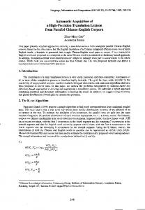
Fig. 1. Components: (a) component A and (b) component B.
protect the components and improve the assembly quality. The developed system with the proposed methods can automatically assemble the two components successfully. The rest of this paper is organized as follows. Section II gives an introduction of system setup and the components to be assembled. In Section III, the measurement techniques including the image feature extraction and the calibration of the image Jacobian matrix are provided. The automatic alignment process is described in Section IV. The aligning control approaches are also provided. The insertion strategy based on force information is given in Section IV. Section V presents the experiments and results. Finally, this paper is concluded in Section VI. II. COMPONENTS AND SYSTEM CONFIGURATION A. Components The two components to be assembled are shown in Fig. 1. Component A is a cylindrical structure object with external diameter of 6 mm and height of 6 mm, while component B is a thin annular structure silicon object with external diameter of approximately 11 mm and thickness of 0.5 mm. The external larger than diameter of upper end of the component A is 20 the internal diameter of the component B. So the assembly of the components A and B is interference fit. There is an incline guidance surface at the top edge of the component A. Its height , it inclines about 30 from the vertical direction. is 60 The internal diameter of the component B can only be theoretically. There are a total of 16 stretched about 40 holes distributed evenly around the components A and B. The assembly target is to insert the component A into the component B in the condition that the surfaces of the two components are parallel to each other and the 16 holes on them are aligned as accurate as possible. B. System Configuration The automated precision assembly system is designed as given in Fig. 2. It consists of a 3-DOF manipulator, a 4-DOF adjusting platform, three optical microscopic cameras, a high precision force sensor, a light system, and a host computer. , , and The 3-DOF manipulator can move along the axis to align component B to component A in position. Its gripper’s orientations can be manually adjusted to initialize the pose of the component B in three microscopic cameras. The 4-DOF adjusting platform consists of three rotation DOFs , , and axis, respectively, and a translation around DOF along the axis. The adjusting platform is used to align
384
IEEE TRANSACTIONS ON AUTOMATION SCIENCE AND ENGINEERING, VOL. 13, NO. 1, JANUARY 2016
Fig. 3. Coordinates system.
Fig. 2. System configuration.
component A to component B in orientations and to move comaxis in order to insert it into component ponent A along the B. The optical axes of the microscopic cameras 1, 2, 3 are ex, , and axis separately. So the pected to be parallel to three optical axes of microscopic cameras are approximately orthogonal. All three microscopic cameras can be moved along their moving platforms on support mechanisms to adjust the distance between the objective lens and components in order to capture clear images. The force sensor is placed on the adjusting platform, while component A is placed on the force sensor. In the assembly procedure, the force sensor will feed back force information in real-time. The position of component B will be and directions according to the force inadjusted in formation in order to assemble them with least resistance. The host computer is used to control the whole assembly procedure, including capturing images from microscopic cameras, image processing, and controlling the adjusting platform and manipulator to align and assemble the two components. The coordinates are established, as shown in Fig. 3. The world coordinates {W} and the manipulation coordinates {M1} are established on the adjusting platform. Manipulation coordinates {M2} is established on the manipulator. The camera coordinates {C1}, {C2}, and {C3} are established on the imaging planes of corresponding microscopic cameras with origins being the and intersection of optical axes and imaging planes. The axes of {C1}, {C2}, and {C3} are along with and axes of their images. The axes of {C1}, {C2}, and {C3} point from origins to component A. III. CALIBRATION AND FEATURE EXTRACTION A. Calibration of Image Jacobian Matrix Image Jacobian matrix is the transformation matrix from incremental motion of the features in the Cartesian space to them on images. In this work, the position and orientation alignments are realized by the manipulator and the adjusting platform separately. The image Jacobian matrixes concerned are rotation maand translation matrix . represents the transformatrix tion from incremental rotation of the feature lines in the Cartesian space to them on images since the adjusting platform ro-
tates component A. represents the transformation from incremental translation of the feature points in the Cartesian space to them on images since the manipulator moves component B. Each microscopic camera is sensitive to one DOF rotation. For example, microscopic camera 1 is sensitive to the rotation axis [15]. The relation of the rotation of component around A in Cartesian space and the rotation of the feature lines on the images of three microscopic cameras can be expressed in (1) if each angle feature is chosen on the image of each microscopic camera.
(1) , , and are the incremental angles on imwhere ages captured by the microscopic cameras 1, 2, and 3, respec, , and are the incremental rotation angles tively; , , and axis, respectively. of component A around Three sub-equations can be formed in (1) with the one step active rotation of the adjusting platform. Therefore, nine subequations can be obtained with three steps of active rotation of the adjusting platform. The elements in the rotation image can be solved from the nine sub-equations Jacobian matrix using least square method. In other words, the rotation image can be calibrated with at least three steps Jacobian matrix of active rotation of the adjusting platform. Of course, more steps of active rotation of the adjusting platform are helpful to improve the calibration accuracy. Each microscopic camera is sensitive to 2-DOF translation [15]. For example, microscopic camera 1 is sensitive to the and axis. The relation of the translations along the translation of component B in Cartesian space and that of the feature points on the images of three microscopic cameras can be expressed in (2) if each feature point is chosen on the image of each microscopic camera [15]
(2)
LIU et al.: HIGH PRECISION AUTOMATIC ASSEMBLY BASED ON MICROSCOPIC VISION AND FORCE INFORMATION
385
Fig. 5. Image features of the two components on the images of the microscopic camera 1. (a) Component B. (b) Component A. Fig. 4. Line features.
where , , and are the increments of the three feature points on the images of the three is the incremental microscopic cameras, translation of component B moved by the manipulator. The microscopic cameras 2 and 3 are employed to measure axis with the the position errors of the two components in and of image consideration that the increments features are difficult to be obtained because of the shapes and sizes of the two components. More details are available in Section III-B. In this case, the relation in (2) is rewritten as given in (3)
(3) is the translation image Jacobian matrix in the case where that the microscopic cameras 2 and 3 are employed to measure axis. the position errors of the two components in Similarly, the elements in the translation image Jacobian matrix can be calibrated with at least three steps of active translation of the manipulator. Of course, more steps of active translation of the manipulator are helpful to improve the calibration accuracy. B. Feature Extraction In this work, the image features are lines and points selected from the two components. The edge lines of the two components are extracted on the images captured by the microscopic , , and cameras 2 and 3 to estimate the angle features . The holes on the two compothe position features nents are extracted on the images captured by the microscopic camera 1 to calculate the angle feature and the position . feature , , and are extracted As shown in Fig. 4, the lines using progressive probabilistic Hough transform (PPHT) [29] from the edge points detected by the Canny operator on the images of the two components captured by the microscopic cam, 3. is the lower edge line of component eras 2 and 3, and are the upper and side edge lines of component B. A. Their equations on image can be expressed as (4)
where , , , , , and are the parameters of lines , , and on the images of the microscopic camera , is the microscopic camera’s serial number, , 3. The angle and position features are computed as
(5)
is the width of the image in pixel, and are where and , ,3. factors corresponding to and are available, then . If If both is available and cannot be extracted, then , . cannot be extracted and is available, then , If . Fig. 5 shows the image features of the two components A and B on the images captured by microscopic camera 1. They are separately extracted from the two images since the image of component A can be only captured by the microscopic camera 1 when component B is moved away. The 16 holes of each component on images are eclipses in view for the upper surfaces of the components are not strictly perpendicular to the camera’s optical axis. First, all 16 eclipses corresponding to the holes of component B are extracted with PPHT method from the edge points detected by the Canny operator. The center for each hole on image is obtained from the corresponding ellipse. Second, the ellipse representing the circle formed by the holes’ center is fitted, whose center’s image coordinate is denoted with . Third, the angle from the horizontal line to the to the th hole’s center is comline from the center puted, as shown in Fig. 4(a). Similarly, and from to the the horizontal line to the line from the center th hole’s center are computed, as shown in Fig. 4(b). Symbol is the serial number of the holes. Then, angle and position features are computed as
(6)
where and are the image coordinates of the centers formed by the holes on the two components, is the angle from the horizontal line to the line from the to the th hole’s center of component B, center is the angle from the horizontal line to the line from the center to the th hole’s center of component A.
386
IEEE TRANSACTIONS ON AUTOMATION SCIENCE AND ENGINEERING, VOL. 13, NO. 1, JANUARY 2016
and , are obtained. Then, and are computed with (5), is computed with (6). The orientations of the component A are adjusted by the adjusting platform to realize the orientation alignment according to the errors , , and . After the orientation alignment is finished, component A is moved down an adequate distance. The microscopic camera 1 is adjusted along the axis in order to capture a clear image of component A. The image features of component A are extracted and the parameters , , , , and are computed. Then, the microscopic camera 1 is moved up to avoid collision with component B. Component B is moved into view to make its images clear in all microscopic cameras. The image features of component B are extracted and the parameters , , , , and are computed. The position feature errors and are calculated with (5), and are computed with (6). The position of component B is adjusted by the manipulator to realize the position alignment according to the errors , , , and . The position alignment is finished once the position errors on the image are less than the given threshold. B. Alignment Control System and Strategy
Fig. 6. The program flow chart of the alignment procedure.
IV. AUTOMATIC ASSEMBLY A. Alignment Procedure The alignment of the two components A and B is separated to orientation alignment and position alignment, both of which are achieved via visual control based on image Jacobian matrix. The whole alignment process is given in Fig. 6. First of all, the initial poses of the two components are manually adjusted to adequate status. In other words, clear images of component B can be captured by the three microscopic cameras and clear images of component A can be captured by the microscopic cameras 2 and 3. The lines and are extracted from the images of component B captured by the microscopic cameras 2 and 3. Their parameters , , , and as listed in (4) are obtained. The image features, as shown in Fig. 4(a), are extracted from the image of component B captured by the microscopic camera 1. The parameters and , are obtained. Then, the component B is moved away, which is out of the views of the three microscopic cameras. Component A is moved up an adequate distance to make its images clear in all microscopic cameras. The lines , , , and are extracted from the images of component A captured by the microscopic cameras 2 and 3. Their parameters , , , , , , , and as listed in (4) are obtained. The image features, as shown in Fig. 4(b), are extracted from the image of component A captured by the microscopic camera 1. The parameters
The designed alignment control system consists of orientation control, position control, and sequence control parts, as shown in Fig. 7. The sequence controller is employed to realize the alignment and auxiliary motions procedure as given in Section IV-A. It sequentially enables gates to in order to execute different operations. For example, the adjusting platform can move component A along the axis when gate is enabled. The orientation alignment is executed when gate is enabled. Both orientation and position control parts are based on visual control with image Jacobian matrix. Their controllers are incremental proportional-integral (PI) controllers. The control laws are given in (7) and (8) for orientation and position alignments. In addition, the symbol represents the pseudo-inverse of image Jacobian matrix
(7) where and are the proportional and integral factors of the PI controller for the orientation alignment, is the sampling moment
(8)
LIU et al.: HIGH PRECISION AUTOMATIC ASSEMBLY BASED ON MICROSCOPIC VISION AND FORCE INFORMATION
387
Fig. 7. The diagram of the alignment control system, and are the exand are the expected and pected and current relative orientation features, current relative position features of the two components.
Fig. 9. The program flow chart of the insertion procedure. Fig. 8. The simplified block diagram of the control system for orientation alignment.
where and are the proportional and integral factors of the PI controller for the position alignment. The adjusting platform and manipulator are driven with stepper motors. The stepper motor can be modeled to a one-order inertial element and an integral element since it works in low speed in the assembly procedure. In this case, the control system for orientation alignment is simplified to the form in Fig. 8. The closed loop is approximate to a PI controller and a one-order inertial element if the rotation image Jacobian matrix is well calibrated. It is sure that the control system is stable if the parameters of the PI controller are well tuned. The stability of the control system for position alignment can also be ensured since it is similar to one for orientation alignment.
Fig. 10. The diagram of the insertion control system.
order to protect the components. It moves component A along the axis by the adjusting platform in order to insert it into component B. The control strategy is designed as given in (9) to (12) (9)
C. Insertion Procedure The insertion procedure is shown in Fig. 9. First, component A is moved up a given distance according to the error threshold specified in the position alignment. Then, the force sensor is active. The forces , , and along the , , and axes are filtered and checked. If , , and are all less than the threshold , component A does not contact component B. Component A is moved up along the axis with the step length by the adjusting platform. Otherwise, component A contacts component B. Then, the forces and are checked if they are larger than the threshold . Component B is adjusted with the step length or along the or axis by the manipulator if or . The force is checked in the case that the forces and are less than the threshold . Component A is moved up along the axis with the step length by the adjusting platform to insert into component B if the force is less than the threshold . The insertion procedure is finished once the force is stably larger than the threshold .
where is the translation of the manipulator along the axis, is the force in axis, is the step length, is the threshold, sig is the sign function as given in (12) (10) where axis,
is the translation of the manipulator along the is the force in axis, is the step length
others (11) is the translation of the adjusting platform along where the axis, is the force in the axis, and are the step lengths, and are the thresholds
D. Insertion Control System and Strategy The insertion control system is designed as given in Fig. 10. It adjusts the position of component B by the manipulator according to the forces and to reduce the radial force in
(12)
388
IEEE TRANSACTIONS ON AUTOMATION SCIENCE AND ENGINEERING, VOL. 13, NO. 1, JANUARY 2016
TABLE I SPECIFICS OF THE MANIPULATOR SUGUAR KWG06030-G
Fig. 11. Experiment system.
V. EXPERIMENTS AND RESULTS A. Experiment System An experiment system was established according to the scheme given in Section II-B, as shown in Fig. 11. In this experiment system, there were three microscopic cameras including two GC2450 cameras and one PointGrey camera. All three cameras equipped with a Navitar zoom lens with magnification 0.47 4.5 , which captured images 15 frames per second with image size of 2448 2050 in pixel. The force sensor was Nano-43, which had a measuring range of 18N and resolution of 1/128N along the , , and axis, respectively. Its signal was in near-zero noise distortion. The low-pass filter combining a Butterworth filter and a mean value filter was designed to filter the force signals. The force signals were first filtered by the Butterworth filter, then filtered by the mean filter. The random noise after filtering was in the range ( 5, 5) mN. The window of the mean value filter was 50. The Butterworth filter was
where
, , , ,
, ,
, , ,
. The adjusting platform was composed of Micos ES-100 for translation along the axis, Micos WT-100 for rotation around the , and axis, and Sigma SGSP-40YAW for rotation around the axis. The rotating resolution of the adjusting platform was 0.02 around axis, 0.001 around , and axis, the translation resolution was 1 . The manipulator was Suguar KWG06030-G, whose translation resolution was 1 along the , , and axis, respectively. All three microscopes were placed on Sigma SGSP26-50 to move along their optical axes. The CPU of host computer was
Intel Core2 DUO with frequency of 2.8 GHz. As an example, the specifics of the Suguar KWG06030-G are listed in Table I. The three microscopic cameras, the adjusting platform, and the manipulator were well regulated according to the coordinates shown in Fig. 3. The decorrelation of image feature changes resulting from the motions in different axes was basically realized in order to conduct the comparative experiments with the method in [3]. B. Image Jacobian Matrixes Calibration The image Jacobian matrixes and were calibrated with the method presented in Section III-A. The adjusting platform actively rotated component A with different angles as shown in matrix , whose column was the incremental rotation angles of component A around , , and axis, respectively. The extracted incremental feature angles were recorded in matrix , whose column was the incremental angles on images captured by the microscopic cameras 1, 2, and 3, respectively. The rotation image Jocabian matrix was computed in (13) shown at the bottom of the next page, where was the matrix formed by the active rotation of the adjusting platform, was the matrix formed by the incremental feature angles. Similarly, the manipulator actively translated component B with different distances as shown in matrix , whose column was the increments of component B along the , , and axis, respectively. The extracted feature increments were recorded in matrix , whose column was the feature increments on images captured by the three microscopic cameras. Then, the translation image Jocabian matrix was computed in (14) shown at the bottom of the next page, where was the matrix formed by the active translation of the manipulator, was the matrix formed by the feature increments. C. Automatic Assembly In the assembly experiments, the features were extracted as described in Section III-B. The threshold for the Canny operator was 100. The edges, as shown in Fig. 4, were classified into three groups according to the areas located. The angle step length in PPHT [29] for line detection was set to 0.1 , and the angle variation was limited in a small range of 10 . In the holes extraction, the HoughCircles function in OpenCV was used since
LIU et al.: HIGH PRECISION AUTOMATIC ASSEMBLY BASED ON MICROSCOPIC VISION AND FORCE INFORMATION
the holes’ profiles were very near to circles. The radius of the circle were limited to 50 pixels. The minimum distance between two circles was 100 pixels. The control parameters were evaluated as follows. , , , , , , , , , , . was set according to the noise range after filtering. was set according to the force tolerance. was set from the test value when the upper ring’s surface of component A reaches the lower surface of component B. was set according to the guidance surface of component A and the impulse force generated in the insertion. was set with the consideration of the small deformation of component B in the direction and the inserting efficiency. and were set from test results. The PI parameters were regulated with the Ziegler–Nichols method. The step lengths and thresholds in force control were determined via experiments. For example, component A could not be moved up further when the force threshold in axis was larger than . In this case, the upper surface of component A tightly contacted with the lower surface of component B, the insertion finished. The expected aligning accuracy was 0.2 for orientation and 5 for position. The orientation alignment finished once the angle errors were less than 0.1 around , , and axis. The position alignment finished once the position errors of component B relative to the align position were less than 2 in Cartesian space along the , , and axis. The align po-
389
above the upper surface of sition was set at the position 150 component A along the axis. The force signal from the force sensor was filtered with the low-pass filter given in Section V-A in the insertion stage. The assembly experiments including orientation alignment, position alignment, and insertion were conducted with the proposed method in Section IV. Component A was well aligned with component B in orientation and position, and was successfully inserted into component B to form an assembled component. The errors in alignment in one experiment were given in Fig. 12. Fig. 12(a) showed the errors in orientation alignment. Fig. 12(b) showed the errors in position alignment. With seven control steps, the final orientation errors around the , , and axis were less than 0.1 . And the errors less than 0.1 could satisfy the assembly accuracy requirements. With eight steps, the position errors along the , , and axis were all less than 2 . It can be seen from Fig. 12 that the whole control progress was performed smoothly and stably in alignment. The force curve and the trajectories of the two components were shown in Fig. 13. Fig. 13(a) was the force along the , , and axis in the process of inserting component A into component B. It can be found that the forces along the and axis were successfully limited to a small range, which was helpful to protect the components in the insertion. Fig. 13(b)
(13)
(14)
390
IEEE TRANSACTIONS ON AUTOMATION SCIENCE AND ENGINEERING, VOL. 13, NO. 1, JANUARY 2016
Fig. 12. The errors in alignment: (a) in orientation alignment and (b) in position alignment.
Fig. 13. Force curve and trajectory in insertion: (a) force curve and (b) trajectory.
showed the trajectories of the two components in the insertion. Component B was adjusted along the and axis in order to reduce the contact forces. It can be seen that the adjusting trajectory of component B and the insertion trajectory of component A were stable. It can also be found from Fig. 13 that the adjustment of component B was efficient to reduce the radial contact forces in the insertion. The total time cost in one assembly was about 115 s. It was as follows, orientation alignment 50 s, position alignment 28 s, insertion 22 s, and auxiliary operation about 15 s. The assembling is successful if the following conditions are satisfied. (1) The 16 holes on the two components are well aligned after the assembly. (2) The 16 pins are not damaged. (3) The upper part of component A is fully inserted into component B. (4) The upper plane of the ring of component A is contacted with the lower plane of component B without gap. 40 assembly experiments were conducted, and all were successful. Fig. 14 showed the images captured by the three microscopic cameras before alignment, after alignment, and after insertion in one assembly experiment. It can be found that the alignment and insertion achieved
good results. The assembled component was shown in Fig. 15 in different views. D. Comparative Experiments The position-based method in [3] was selected as the comparative method. The microscopic cameras, the adjusting platform and the manipulator were well regulated to decouple the image changes resulting from the translations of the components along different axes. The scales for the three microscopic cameras were calibrated according to the distances moved in Cartesian space and ones on images. for the microscopic camera 1, for the microscopic camera 2, for the microscopic camera 3. The incremental angles on images were considered as same as ones in Cartesian space, that is, , , and . In the comparative experiments, the parameters of the controllers in orientation and position alignments with the method in [3] were the same as the ones with the proposed method.
LIU et al.: HIGH PRECISION AUTOMATIC ASSEMBLY BASED ON MICROSCOPIC VISION AND FORCE INFORMATION
391
TABLE III ERRORS AND STEPS IN POSITION ALIGNMENT
Fig. 14. Images in different stages, image captured by: (a) microscopic camera 1, (b) microscopic camera 2 and (c) microscopic camera 3 before alignment, (d) microscopic camera 1, (e) microscopic camera 2 and (f) microscopic camera 3 after alignment, (g) microscopic camera 1, (h) microscopic camera 2 and (i) microscopic camera 3 after insertion.
Tables II and III, respectively. It can be found that the errors could converge in desired range with very few steps. The steps needed for the proposed method were fewer than ones for the position-based methods in [3]. However, it is noted that the position-based method in [3] requires complex regulation in advance to decouple the image changes resulting from the translations of the components along different axes. The proposed method doesn’t need. In other words, the proposed method has equivalent effectiveness but has more flexible and convenience. VI. CONCLUSION
Fig. 15. The assembled component: (a) up view and (b) side view.
TABLE II ERRORS AND STEPS IN ORIENTATION ALIGNMENT
A series of comparative experiments were well conducted. Component A was also well aligned with component B in orientation and position, and was successfully inserted into component B to form an assembled component with the method in [3]. The errors and steps of ten groups of comparative experiments in orientation alignment and position alignment were listed in
The main contribution of this work is the aligning and insertion strategy to realize the assembly in 3-D space with 6 DOFs and the vision-based positioning of components including calibration of three orthogonal camera systems and offset calculation of components by using image features. The pose aligning is achieved with two steps such as the orientation aligning and the position aligning. In the orientation aligning step, the orientations of component A is adjusted with the adjusting platform to align the orientations of component B according to the errors measured by the three microscopic cameras. In the position aligning step, the position of component B is adjusted with the manipulator to reduce the position errors between the two components. The orientation and position alignments are realized using image-based visual control scheme with image Jacobian matrixes. The proposed two-step aligning strategy can decouple the orientation and position adjustments, which simplifies the pose aligning process and mechanical system. Only three rotational degrees of freedom are needed for the adjusting platform, and three translational degrees of freedom are needed for the manipulator. In the insertion stage, component A is moved up along the axis by the adjusting platform to insert into component A. The positions of component B along the and axis are adjusted in the insertion process according to the contact forces in order to protect the components and ensure the assembly quality. The three orthogonal microscopic cameras are separately calibrated with the active movements of the manipulator and the adjusting platform. A series of experiments including the comparative ones with the position-based method in [3] are well conducted. The assembly can be finished in 2 min. The alignment errors are less than in position and 0.1 degree in orientation. The
392
IEEE TRANSACTIONS ON AUTOMATION SCIENCE AND ENGINEERING, VOL. 13, NO. 1, JANUARY 2016
successful rate in 40 assembly experiments is 100%. The experimental results verify the effectiveness of the proposed assembly system and methods. In addition, the proposed method has the advantages over the comparative method in the aspects of flexibility and convenience since the proposed method does not need the complex decoupling regulation in advance. In the future, our work will be focused on the intelligent control methods in the alignment and insertion process.
REFERENCES [1] L. D. Wang, J. K. Mills, and W. L. Cleghorn, “Automatic microassembly using visual servo control,” IEEE Trans. Electron. Packag. Manuf., vol. 31, no. 4, pp. 316–325, Oct. 2008. [2] Z. Zhang, J. Zhang, and D. Xu, “Design of microassembly system and research on coarse-to-fine alignment strategy in combination with active zooming,” in Proc. IEEE Winter Vision Meetings, Workshop on Robot Vision, Clearwater Beach, FL, USA, Jan. 15–17, 2013, pp. 76–81. [3] J. Zhang, D. Xu, Z. T. Zhang, and W. S. Zhang, “Position/force hybrid control system for high precision alignment of small gripper to ring object,” Int. J. Autom. Comput., vol. 10, no. 4, pp. 360–367, Aug. 2013. [4] L. Wang, L. Ren, J. K. Mills, and W. L. Cleghorn, “Automated 3-D micrograsping tasks per-formed by vision-based control,” IEEE Trans. Autom. Sci. Eng., vol. 7, no. 3, pp. 417–426, Jul. 2010. [5] P. I. Corke and S. A. Hutchinson, “A new hybrid image-based visual servo control scheme,” in Proc. 39th IEEE Conf. Decision Control, Sydney, NSW, Australia, Dec. 12–15, 2000, vol. 3, pp. 2521–2526. [6] B. Zhang, J. Wang, G. Rossano, C. Martinez, and S. Kock, “Visionguided robot alignment for scalable, flexible assembly automation,” in Proc. IEEE Int. Conf. Robot. Biomimetics, Karon Beach, Thailand, Dec. 07–11, 2011, pp. 944–951. [7] J. A. Gangloff and M. F. de Mathelin, “High-speed visual servoing of a 6-dof manipulator using multivariable predictive control,” Adv. Robot., vol. 17, no. 10, pp. 993–1021, 2003. [8] B. Kim, H. Kang, D. H. Kim, G. T. Park, and J. O. Park, “Flexible microassembly system based on hybrid manipulation scheme,” in Proc. IEEE/RSJ Int. Conf. Intell. Robot. Syst., Las Vegas, Nevada, USA, Oct. 27–Nov. 1, 2003, vol. 2, pp. 2061–2066. [9] L. Wang, L. Ren, J. K. Mills, and W. L. Cleghorn, “Automatic 3d joining in microassembly,” in Proc. Int. Conf. Inform. Acquisition, Hyatt Regency Jeju Seogwipo-si, Korea, Jul. 08–11, 2007, pp. 292–297. [10] X. Huang, X. Lv, and M. Wang, “Development of a robotic microassembly system with multi-manipulator cooperation,” in Proc. IEEE Int. Conf. Mechatronics Autom., Luoyang, China, Jun. 25–28, 2006, pp. 1197–1201. [11] A. N. Das, R. Murthy, D. O. Popa, and H. E. Stephanou, “A multiscale assembly and packaging system for manufacturing of complex micronano devices,” IEEE Trans. Autom. Sci. Eng., vol. 9, no. 1, pp. 160–170, Jan. 2012. [12] Z. Yang, B. Zhou, F. Wang, and J. J. Lian, “An algorithm of monocular vision for spatial position based on the mirror image,” in Proc. IEEE 3rd Int. Conf. Commun. Softw. Netw., Xi’an, China, May 27–29, 2011, pp. 525–528. [13] L. Chen, M. Wang, Z. Yang, and W. Rong, “Fast autofocus method for microscopic computer vision,” Opt. Precision Eng., vol. 18, no. 6, pp. 1361–1366, 2010. [14] H. Li, H. Zhu, J. Li, S. Yang, and Y. Xue, “Micro-table posture measuring based on binocular vision,” in Proc. 9th Int. Conf. Electron. Meas. Instruments, Beijing, China, Aug. 16–19, 2009, pp. 1-1036–1-1039. [15] D. Xu, F. Li, Z. Zhang, Y. Shi, H. Li, and D. Zhang, “Characteristic of monocular microscope vision and its application on assembly of micropipe and micro-sphere,” in Proc. 32nd Chinese Control Conf., Xi’an, China, Jul. 26–28, 2013, pp. 5758–5763. [16] W. Yuan, G. Jiang, Y. Wang, M. Yu, F. Shao, and Z. Peng, “Grid-based corner detection of the microscopic camera calibration,” Adv. Mater. Res., Adv. Meas. Test, vol. 301–303, pp. 1145–1150, 2011.
[17] H. W. Schreier, D. Garcia, and M. A. Sutton, “Advances in light microscope stereo vision,” Exp. Mech., vol. 44, no. 3, pp. 278–288, Jun. 2004. [18] Y. Zhou and B. J. Nelson, “Calibration of a parametric model of an optical microscope,” Opt. Eng., vol. 38, no. 12, pp. 1989–1995, Dec. 1999. [19] J. Pan, Y. Niu, and Y. Xing, “A fast calibration method of optical microscopes,” in Proc. IEEE Int. Conf. Robot. Autom., St. Paul, MN, USA, May 14–18, 2012, pp. 943–946. [20] A. N. Das, P. Zhang, W. H. Lee, D. Popa, and H. Stephanou, “ : Multiscale, deterministic micro-nano assembly system for construction of on-wafer microrobots,” in Proc. IEEE Int. Conf. Robot. Autom., Roma, Italy, Apr. 10–14, 2007, pp. 10–14. [21] X. Hu, F. Zuo, and K. Xie, “Research on hand-eye calibration method for micro-assembly robot,” Chinese J. Sci. Instrument, vol. 33, no. 7, pp. 1521–1526, Jul. 2012. [22] X. Zeng, X. Huang, and M. Wang, “Micro-assembly of micro parts using uncalibrated microscopes visual servoing method,” Inf. Technol. J., vol. 7, no. 3, pp. 497–503, 2008. [23] X. Tao, F. Janabi-Sharifi, and H. Cho, “An active zooming strategy for variable field of view and depth of field in vision-based microassembly,” IEEE Trans. Autom. Sci. Eng., vol. 6, no. 3, pp. 504–513, Jul. 2009. [24] L. Ren, L. Wang, J. K. Mills, and D. Sun, “Vision-based 2-D automatic micrograsping using coarse-to-fine grasping strategy,” IEEE Trans. Ind. Electron., vol. 55, no. 9, pp. 3324–3331, 2008. [25] H. K. Chu, J. K. Mills, and W. L. Cleghorn, “Fabrication of a microcoil through parallel microassembly,” in Proc. IEEE Int. Conf. Robot. Autom., St. Paul, MN, USA, May 14–18, 2012, pp. 5050–5055. [26] B. Tamadazte, T. Arnould, S. Dembele, N. Le Fort-Piat, and E. Marchand, “Real-time vision-based microassembly of 3D MEMS,” in Proc. IEEE/ASME Int. Conf. Adv. Intell. Mechatronics, Singapore, Jul. 14–17, 2009, pp. 88–93. [27] M. Rakotondrabe and I. A. Ivan, “Development and force/position control of a new hybrid thermo-piezoelectric microgripper dedicated to micromanipulation tasks,” IEEE Trans. Autom. Sci. Eng., vol. 8, no. 4, pp. 824–834, Oct. 2011. [28] K. Rabenorosoa, C. Clevy, and P. Lutz, “Hybrid force/position control applied to automated guiding tasks at the microscale,” in Proc. IEEE/RSJ Int. Conf. Intell. Robot. Syst., Taipei, Taiwan, Oct. 18–22, 2010, pp. 4366–4371. [29] C. Galambos, J. Kittler, and J. Matas, “Gradient-based progressive probabilistic Hough transform,” IEE Vision Image Signal Process., vol. 148, no. 3, pp. 158–165, 2002.
Song Liu received the B.Sc. degree from Shandong University, Jinan, China, in 2012, in sensing technology and instrumentation. He is currently working towards Ph.D. degree at the Institute of Automation, Chinese Academy of Sciences (IACAS), Beijing, China, in control science and engineering. His current research interests include visual measurement, visual control, visual positioning, and micro-assembly.
De Xu (M’05–SM’09) received the B.Sc. and M.Sc. degrees from the Shandong University of Technology, Jinan, China, in 1985 and 1990, respectively, and the Ph.D. degree from Zhejiang University, Hangzhou, China, in 2001, all in control science and engineering. He has been with Institute of Automation, Chinese Academy of Sciences (IACAS) since 2001. He is currently a Professor with the Research Center of Precision Sensing and Control, IACAS. His current research interests include robotics and automation such as visual measurement, visual control, intelligent control, welding seam tracking, visual positioning, microscopic vision, and micro-assembly.
LIU et al.: HIGH PRECISION AUTOMATIC ASSEMBLY BASED ON MICROSCOPIC VISION AND FORCE INFORMATION
Dapeng Zhang received the B.Sc. and M.Sc. degrees from the Hebei University of Technology, Tianjin, China, in 2003 and 2006, respectively, and the Ph.D. degree from the Beijing University of Aeronautics and Astronautics, Beijing, China, in 2011. He is currently an Associate Professor with the Research Center of Precision Sensing and Control, Institute of Automation, Chinese Academy of Sciences (IACAS). His research interests include robotics and automation, in particular, medical robot, and virtual robotic surgery.
393
Zhengtao Zhang received the B.Sc. degree from the China University of Petroleum, Dongying, China, in 2004, and the M.Sc. degree from the Beijing Institute of Technology, Beijing, China, in 2007, and the Ph.D. degree from the Institute of Automation, Chinese Academy of Sciences (IACAS), Beijing, China, in 2010, all in control science and engineering. He is a Professor with the Research Center of Precision Sensing and Control, IACAS. His research interests include visual measurement, micro-assembly, and automation.