High Speed CT Image Reconstruction using FPGA. ABSTACT. Tomographic image reconstruction methods suffer from time consuming back projection steps ...
International Journal of Computer Applications (0975 – 8887) Volume 22– No.4, May 2011
High Speed CT Image Reconstruction using FPGA Payal Aggarwal
Rajesh Mehra
Faculty Member, ECE Department GITM, Gurgaon, India-122001
Assistant Professor, ECE Department NITTTR, Chandigarh, India- 160019
ABSTACT Tomographic image reconstruction methods suffer from time consuming back projection steps due to large computation. This drawback can be minimized by its hardware implementation on FPGA to provide high speed image reconstruction. This paper presents the reconfigurable design of filtered backprojection (FBP) for parallel beam CT. The proposed design has been implemented by efficiently utilizing the embedded multipliers and LUTs of target FPGA device. The design has been developed using MATLAB and synthesized with Xilinx synthesis tool (XST) and implemented on Virtex 2 Pro based xc2vp30-7ff896 target device. The results show that the proposed design can operate at a maximum frequency of 144.744 MHz to provide high speed solution for image processing applications.
KEYWORDS Computed Tomography, FPGA, LUT, MATLAB, VHDL
1. INTRODUCTION Computed Tomography (CT) is a medical imaging technique used to create cross-sectional images from x-ray transmission data acquired by a scanner. The impact of this technique in diagnostic medicine has been revolutionary, since it has enabled doctors to view internal organs with unprecedented precision and safety to the patient. In a tomographic system, the primary computational demand after data capture by the scanner is the backprojection of the acquired data to reconstruct the internal structure of the scanned object. The most commonly used approach for image reconstruction from dense projection data is filtered backprojection [1]-[2]. This method reduces the complexity of the reconstruction process and enables the production of high-quality images within a reasonable amount of time. Other algorithms theoretically produce better image quality as compare to filtered backprojection method, but their use involves some compromises. The full iterative reconstruction is fundamentally insensitive to noise and has the capability to reconstruct an optimal image from incomplete data. But these algorithms are so computationally challenging that image reconstruction would take seconds or minutes, as opposed to a fraction of a second. Computed Tomography deals with highly data intensive computer images that leads to extremely computationally extensive data and hence it ultimately slows down the image reconstruction speed. But by applying the latest high-performance processors, it is possible to reduce the
processing time. With the resulting performance gains, CT scanners operate faster while also enhancing image quality and increasing acquisition flexibility. These advances in CT imaging enable radiologists to improve patient care and reduce the time to diagnosis. Various algorithms have been proposed to enhance the speed of computations required for CT image reconstruction [3]-[5]. The acceleration of CT image reconstruction focuses on two methods. One of the methods concentrates on software acceleration by improving algorithm [6]. And the other one relies on hardware acceleration by Graphic Processing Unit (GPU) or Field Programmable Gate Arrays (FPGA). GPUs are easy to program using high level languages [7]-[8]. In comparison with FPGAs, GPU has fixed hardware architecture whereas FPGAs are essentially high density arrays of uncommitted logic and are more flexible. The developers can directly use module-to-module hardware infrastructure and trade-off resources and performance by selecting the appropriate level of parallelism to implement an algorithm on FPGA. Hence FPGA implementation has attracted the attention of many researchers [9]-[11]. These processors offer a large number of simple programmable logic. The combination of this programmable logic is capable of dramatically accelerating the image reconstruction process. Hardware description Language such as VHDL is often used to implement the algorithm on FPGA [12]. The hardware implementation with the help of VHDL language found remarkable differences in execution time which makes the use of reconfigurable hardware inevitable for real-time applications of such algorithms. Other research methods include hybrid languages for application developers to improve their productivity on FPGA. These languages are Catapult C, Impulse C, Mitrion-C, Spark and Trident. These languages provide high level programming models and transparent device drivers for application developers. But there are still some limitations for these languages. One of the major drawbacks is the loss of fine grained control over the resulting hardware. There is an interesting implementation that uses FPGA as co-processor to accelerate two-dimensional CT image reconstruction. The design is based on the Impulse C language [13]. Although the design time has been decreased using Impulse C but still execution time required to reconstruct the image was smaller in case of VHDL. Hence this paper focuses on accelerating the tomographic image reconstruction based on filtered backprojection algorithm on FPGA Virtex2 Pro target device with the help of VHDL.
7
International Journal of Computer Applications (0975 – 8887) Volume 22– No.4, May 2011
2. IMAGE RECONSTRUCTION
The problem of reconstruction can be viewed as the problem of transforming the sinogram into the image space (X, Y). Backprojection simply reverses the measurement process and can be thought of as smearing the projections back across the reconstructed image. In other words, the reconstruction is obtained by wiping each projection back across the image at the angle at which it was acquired. Simple backprojection of the sinogram space into the image space will generate images with a blurring effect around the edges of the object. To eliminate this blurring effect, one technique often used is the application of a high pass filter to the sinogram data prior to backprojection. This technique is known as Filtered Backprojection (FBP). The mathematical expression for reconstructed image function is given by equation (1)
30
-80
-60 25
Sensor Position (pixels)
In this type of tomography, projections are obtained by a number of sensors that measure the intensity of X-rays travelling through a slice of the scanned object. The radiation source and the sensor array rotate around the object in small increments. The sources and detectors in the gantry can come in two configurations, leading to distinct beam geometries as parallel beam and fan beam. The algorithms for both of the geometries are based on the discrete Radon transform [14], which extends the continuous Radon transform to discrete data. This paper work will focus on parallel beam projected data. Parallel beam geometry has a linear array of sources and detectors where one projection is taken for each rotational angle by moving the source-detector pair along parallel lines. The image reconstruction process uses these projections to calculate the average X-ray attenuation coefficient in crosssections of a scanned slice. Since different parts of the human body have different attenuation coefficients for the incident X-rays, the viewer is able to differentiate between bones and different tissues in the reconstructed image. The set of all projections acquired by a scanner is a two dimensional matrix of data. This data represents a 2D spatial function termed as sinogram.
-40 20
-20
0
15
20 10 40
5
60
80 0
20
40
60
80
100
120
140
160
0
Angle (theta)
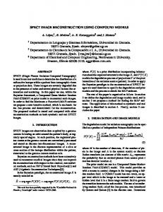
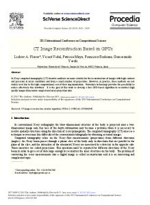
Figure1. Sinogram To reconstruct the original image without blur, the projection data is filtered with the help of high pass ramp filter before backprojection. This data is then stored in a text file. The filtering is performed in the spatial domain. The high pass ramp filter is first created in the frequency domain, and then transformed into a 121-tap symmetric FIR filter. This approach saves the need to implement FFT and IFFT in hardware. The ramp filter created in frequency and spatial domain is shown in Figure 2. Frequency Domain Ramp Filter 1
0.8
0.6
0.4
0.2
0 -pi
-pi/2
0
pi/2
pi
Spatial Domain Ramp Filter 1 0.8 0.6
(1)
0.4 0.2 0
Where
-0.2 -0.4
(2) Equation (2) represents a filtering operation, where the frequency response of the filter is given by | w |; therefore is called a “filtered projection”. The resulting projections for different angles are then added to form the estimate of f(x, y)
3. PROPOSED DESIGN SIMULATION The projection data of the Shepp Logan head phantom image has been obtained from MATLAB using radon function. This data can be plotted to get the sinogram as shown in figure 1. The figure shows the sinogram plotted as s function of angle and the sensor position.
20
40
60
80
100
120
Figure 2. Ramp Filter in Frequency & Spatial Domain The stored text file is copied to Xilinx project folder where the VHDL code has been written for the filtering subsystem. In the filtering subsystem, the output of the filter is stored in a memory buffer. While the filtered projection of the current angle is written into one bank of the buffer, the filtered projection of the previous angle is read out from the other bank and used in the following backprojection step. This kind of data buffering scheme can be effectively implemented using the dedicated RAM resources in an FPGA during synthesis. The design is simulated using simulation software ModelSim SE Version 6.2h [15]. On each clock cycle, the model outputs new
8
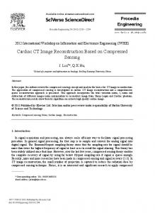
International Journal of Computer Applications (0975 – 8887) Volume 22– No.4, May 2011 partial pixel containing the contribution from one angle. To form the final image, the contribution from one angle must be added to that of the next angle, until the last angle is calculated. Therefore it takes a total of (180/angle resolution)*(image size ^2) cycles to reconstruct one frame of the image. After simulation the reconstructed image is generated in the form of a text file which is read and displayed in Matlab. Figure 3 shows the final reconstructed image of head phantom as well as the input image for comparison.
Table2. Comparison of Device Utilization No. of Logic used
Spartan 2
Slices Flip Flops
3527/768 3947/1536
LUTs IOBs BRAMs Multipliers
4686/1536 51/92 4/8 __
Spartan 3
Virtex 2Pro
(Used/Available) 2631/4656 2227/13696 3952/9312 3950/27392 2969/9312 51/232 2/20 20/20
2219/27392 51/556 2/136 27/136
The table shows the excellent utilization of the device resources by Virtex 2Pro as compare to Spartan 3 and Spartan 2. The utilization of LUTs and multipliers by Virtex 2Pro further helps in accelerating the speed of CT image reconstruction. Hence, as more high density FPGA chips are used with efficient utilization of LUTs, Block RAMs, Bonded IOBs and Multipliers, it will become more efficient in terms of speed and area and more cost effective.
5. CONCLUSION (a)
(b)
Figure3. (a) Input image (Head Phantom) (b) Reconstructed Image of Head Phantom
4. H/W IMPLEMENTATION RESULTS Table 1 shows timing summary of FPGA implementation on the target device Xilinx Virtex2Pro xc2vp30-7ff896 Board. The biggest achievement is the clock frequency which comes out to be 144.744 MHz. The value achieved with this clock frequency effectively reduces the time taken for CT image reconstruction. Table 1 shows the timing summary of FPGA Virtex2 Pro target device. Table 1 Timing Summary of FPGA Virtex2 Pro Target Device
xc2vp30-7ff896
Maximum Frequency
144.744 MHz
Minimum input arrival time before clock Maximum output required time after clock Maximum combinational path delay
7.297 ns 3.293 ns 4.793 ns
Since the medical image processing needs to be very accurate and fast, hence speed optimization is necessary which can further be achieved by using embedded multiplier and accumulator (MAC) architecture and look up tables (LUT) along with FPGA. Many fundamental algorithms such as FIR filters or the Fast Fourier Transform depend heavily on multiply-accumulate performance. Hence the FIR filter designed here is benefitted greatly from the embedded MAC architecture which is being used with FPGA Virtex2 pro target device in order to enhance the image reconstruction speed. Table 2 shows the comparison of logic utilization for Spartan 2, Spartan 3 and Virtex2 pro device.
Computed tomography contains computationally complex algorithm which requires the rapid processing of large amount of data. Hence, hardware implementation is necessary. FPGA implementation is more suitable for hardware implementation because of its flexibility and simpler design cycle. Implementation on an FPGA device accelerates the image reconstruction algorithms by using parallel architectures. The main affecting factor on acceleration ratio in this paper is the use of embedded multipliers of target FPGA. The developed image reconstruction design can operate at a maximum frequency of 144.744 MHz by consuming 8% LUTs, 1% BRAMs and 19% multipliers of Virtex2 Pro based xc2vp30-7ff896 target FPGA to provide cost effective high performance solution for image processing applications.
6. ACKNOWLEDGMENT The authors would like to thank Dr. S. Chatterji, Professor and Head and Dr. Swapna Devi, Associate Professor, Electronics & Communication Engineering Department, NITTTR, Chandigarh for constant encouragement and guidance during this research work.
7. REFERENCES [1] Jun Zhao,Yann Jin,Yang Lu, Ge Wang, “ A filtered backprojection algorithm for triple-source helical cone-beam CT”, IEEE Trans. On Medical Imaging, vol. 28, no.3, pp. 384-393, March 2009. [2] Liang Li, Zhiqiang Chem, Yuxiang Xing, Li Zhang, Kejun Kang, Ge Wang, “ A general exact method for synthesizing parallel-beam projections from conebeam projections by filtered backprojection”, In Proceedings of the IEEE Nuclear Science Symposium Conference Record, vol. 6, no.21,pp. 3476-3479, 2006.
9
International Journal of Computer Applications (0975 – 8887) Volume 22– No.4, May 2011 [3] Jingfei Deng, Bin Yan, Jianxin Li, Lei Li, China Nat, “Parallel no-waiting pipelining accelerating CT image reconstruction based on FPGA”, In Proceedings of the 3rd IEEE International Conference on Biomedical Engineering and Informatics, pp. 451-455,BMEI 2010. [4] M. KachelrieB, M. Knaup, and O. Bockenbach, “Hyperfast parallel-beam and cone-beam backprojection using the cell general purpose hardware”, International Journal of Medical Physics Research and Practice, vol. 34, No.4, pp. 1474-1486, 2007 [5] M. Knaup and M. KachelrieB, “Acceleration techniques for 2D parallel and 3D perspective forward and backprojections”, In Proceedings of the 1st Workshop on High Performance Image Reconstruction and the 9th International Meeting on Fully 3D Image Reconstruction, pp. 45-48, 2007. [6] S. Basu and Y. Bresler,“O(N2 log2 N) filtered backprojection reconstruction algorithm for tomography”, IEEE Trans. on Image Processing ,vol. 9, No. 10, pp. 1760–1773, October 2007. [7] Scherl H, Keck B, Kowarschik M and Hornegger J “Fast GPU-based CT reconstruction using the Common Unified Device Architecture,” In Proceedings of IEEE Nuclear Science Symposium Conference Record, vol.6, pp. 4464-4466, NSS 2007. [8] Y. Okitsu, F. Ino and K. Hagihara, “Accelerating Cone Beam Reconstruction Using the CUDA-Enabled GPU”, In Proceedings of the 15th International Conference on High Performance Computing (HiPC), pp. 108-119, 2008 [9] M. Leeser, “Parallel-beam backprojection: An FPGA implementation optimized for medical imaging”, In Proceedings of the ACM/SIGDA 10th International Symposium on Field-programmable gate arrays, pp. 217-226, 2002 [10] D. Stsepankou, K. Kornmesser and J. Hesser, “FPGA acceleration of cone-beam reconstruction for the X-ray CT”, In Proceedings of the IEEE International Conference on Field-Programmable Technology, The University of Queensland, pp. 327-330, 2004 [11] Zhiqiang Que, Yongxin Zhu, Xuan Wang, Jibo Yu, Tian Huang, Zhe Zheng, Li Yang,Feng Zhao and Yuzhuo Fu,“ Implementing Medical CT algorithms on Stand-alone FPGA based systems using an efficient
workflow with Sysgen and Simulink”, In Proceedings with 10th IEEE International Conference on Computer and Information Technology, pp. 2391-2396,2010 [12] Pranamita Basu and Prof. Manjunatha M., “VHDL Modeling and Simulation of Parallel-Beam Filtered Backprojection for CT Image Reconstruction”, In Proceedings of the IEEE International Conference on Multimedia, Signal Processing and Communication Technologies, pp. 213-216, 2009 [13] Jimmy Xu, Nikhil Subramanian, Adam Alessio and Scott Hauck, “Impulse C vs. VHDL for Accelerating Tomographic Reconstruction”, In Proceedings of the 18th IEEE Annual International Symposium on FieldProgrammable Custom Computing Machines, pp. 171174, 2010 [14] A. Averbuch, R.R. Coifman, D.L. Donoho, M. Israeli, Y. Shkolnisky and I. Sedelnikov, “A framework for discrete integral transformations II – the 2D discrete Radon transform”, International Journal on Scientific Computing, vol. 30, No.2, pp. 785-803, SIAM 2008 [15] ModelSim SE User’s Manual Version 6.2h, May 2007
8. AUTHORS PROFILE Payal Aggarwal: Mrs.Payal Aggarwal is currently Lecturer at Gurgaon Institute of Technology & Management, Gurgaon, India. She is pursuing her ME from NITTTR Chandigarh, Panjab Univerity, Chandigarh, India. She has completed her B.Tech. from H.E.C, Jagadhari, Kurukshetra, University, Haryana, India. Mrs. Aggarwal has 6 years of academic experience. Her areas of interest are VLSI Design, Image Processing and Digital System Design. Rajesh Mehra: Mr. Rajesh Mehra is currently Assistant Professor at National Institute of Technical Teachers’ Training & Research, Chandigarh, India. He is pursuing his PhD from Panjab University, Chandigarh, India. He has completed his M.E. from NITTTR, Chandigarh, India and B.Tech. from NIT, Jalandhar, India. Mr. Mehra has 15 years of academic experience. He has authored more than 15 research papers in reputed International Journals and more than 30 research papers in National and International conferences. Mr. Mehra’s interest areas are VLSI Design, Embedded System Design, Advanced Digital Signal Processing, Wireless & Mobile Communication and Digital System Design. Mr. Mehra is life member of ISTE.
10