A high speed 3D reconstruction method using mul- tiple video cameras is presented. The video cameras are set to surround the real 3D space where people.
MYA79R IAPR Workshop on Machine Vision Applications, Nov. 17-19, 1998, Makuhari, Chiba, Japan
11-5 High Speed 3D Reconstruction by Video Image Pipeline Processing And Division of Spatio-Temporal Space Yoshinari Kameda*
Takeo Taodat
Michihiko Minoht
Center for Information Graduate School of Engineering, Center for Information Kyoto University And Multimedia Studies§, And Multimedia Studies§, Kyoto University Kyoto University
Abstract A high speed 3D reconstruction method using multiple video cameras is presented. The video cameras are set to surround the real 3D space where people exist. Reconstructed 3D space is displayed in voxel format and a user can see the space from any viewpoint with a VR viewer. We implemented a prototype system that can work out the 3D reconstruction with the speed of 7.2f p s in 560ms delay.
1
Introduction
With improvement in processing speed of computers and with increase of their storage size, it may come true to synchronize a virtual space in computers with a real 3D space[5]. Our final goal is to construct a real-time virtual space which displays human activities in a certain real space. Once the virtual space is constructed, anyone outside the real space can observe the human activities in the real space from any viewpoint with a little delay. To synchronize the virtual space with the real space, the real space should be reconstructed in realtime. Slit light projection methods and structured light projection methods achieve real-time 3D reconstruction, but these methods require active sensing which disturbs human activities in the real space. On the contrary, passive vision based approach[3,4] does not affect the activities. Stereo vision methods achieve real-time 3D reconstruction though they cannot reconstruct backside shapes that cannot be seen by stereo cameras. Therefore, the cameras have to be placed so as to surround the real space. Realistic 3D reconstruction methods[l, 21 have been proposed which uses over ten cameras, but their approaches need certain period to reconstruct one scene and are not suitable for real-time applications. The main problem of 3D reconstruction with such camera surrounding layout is that it requires much calculation time because there are many images at *Email: kamedaOmedia.kyotc-u.ac.jp tcurrently NEC Software Chugoku $Email: minohQmedia.kyot*u.ac.jp §Address: Yoshidahonmachi,Sakyoku,Kyoto,606-8501,Japan. URL:http://www.imell.kuis.kyoto-u.ac.jp
each frame. This problem is resolved by distributed computing in our approach. We reconstruct the real space by preparing one computer for each camera to execute image processing, and other computers to calculate 3D reconstruction. All the computers are connected one another with lOObaseT Ethernet and 155Mbps ATM LAN. We describe the reconstructed space by voxel r e p resentation. In our method, we improve throughput by dividing video processing into some stages and forming them as the pipeline processing, and decrease latency by dividing a real 3D space into some subspaces and reconstructing each subspace simultaneously with several distributed computers. We can also control throughput and latency by changing the pipeline formation in the system and satisfies the requirements of the applications. In the following sections, Section2 describes how to reconstruct 3D scene in this method, and in Section3 we explain the prototype system named SCRAPER and show experimental results. We conclude this paper in Section4.
3D Reconstruction Method
2
The reconstruction algorithm has to be suitable for the distributed computing, so that the algorithm has the following two characteristics. a a
It is possible to equalize processing time of each process by dividing program and data. The amount of communication among processes is not so much.
The viewing frustum method (VFM) satisfies these two characteristics. With VFM, we reconstruct the real space in realtime by generating voxel data from several images taken at the same time. We call the part of the real space which can be imaged by the cameras the target space.
2.1
Static Object Occupation Subspace (SOOS)
Since our objective is to reconstruct a certain real space where people work, it is reasonable to have a
knowledge of static ob-jects in the space in advance. As the static objects do not changk their positions and shapes, we can exclude the subspace where the static objects occupy. We call the subspace as static object occupation subspace (SOOS) denoted by S. If we see the target space from the viewpoint of camera i, some subspaces cannot be seen because S occludes them. We merge these occluded subspaces into S and call it static object influence subspace (SOIS) S;. From now on, we concentrate on reconstructing the voxels which represent dynamic objects in the target space.
2.2
3D Reconstruction
When the dynamic objects are imaged by a camera
i, they exist within frustums that circumscribe their projected regions on the image and whose apexes are focus point of the camera. We call all the projected regions in the same image together a dynamic region Di and let us denote a subspace consisting of these viewing frustums by V ; . As the dynamic objects can exist only outside S;, we only care a subspace named existence shadow subspace (ESS) U;defined by Equation (1).
The dynamic objects exist somewhere inside U;. In the case where the dynamic objects are imaged by n cameras, they exist within the product of all of these frustums. We denote this subspace as U where
Suppose there are n cameras in the real space and the cameras capture images simultaneously. We call this set of images a frame. 3D reconstruction process named 3D composer can generate U at each frame in the condition that it is given D l , D2,. ..,Dn because S and the focus positions of the cameras are given in advance. Since D; is described by a binary image, the amount of transferred data is quite small. This 3D reconstruction calculation in Equation (2) is easily expanded t o parallel distributed computing because several 3D composers can reconstruct different subspaces simultaneously. Thus we achieve spatio-division of the 3D reconstruction process based on the locality of 3D reconstruction calculation. In the actual implementation, 3D composer generates U by voxel representation.
2.3
Pipeline Processing
Our 3D reconstruction system named SCRAPER can be divided into three stages. 1. image capture 2. extraction of dynamic region
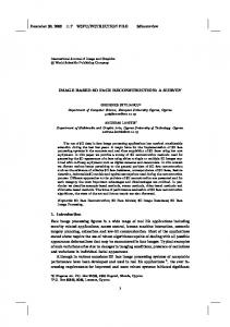
3. ESS calculation by VFM method Let us call this sequence of stages a path. If the 3D reconstruction is done in this order sequentially, some parts of the system always idle. For example, when images are being captured, extraction and ESS calculation cannot be done. As a result, throughput is low and that is not desirable for real-time VR applications. To improve the throughput, we propose to activate several paths simultaneously in the pipeline architecture. We prepare three kinds of processes: image captor, extractor, and 3 0 composer and increase number of these processes to support multiple paths. In our prototype system, an image is captured by the video-capture card for which &U power is not necessary whereas an extractor needs CPU power because it extracts D; by detecting regions where the pixel values differ from its background image taken beforehand, so the two processes need only one CPU to work together. In addition, captured image data which is transferred to the extractor is not small and so it is not desirable to use physical network device to transmit the data between them. Therefore, We assign one video image captor and one extractor on the same workstation. As a result. the number of video image captors and that of the extractors are the same as that of the cameras. On the contrary, the number of 3D composers can be increased because the calculation on the 3D composer is completely localized. The system can improve the throughput by preparing the 3D composers on different workstations distributed in a LAN. As a consequence, the throughput is improved by preparing the multiple paths in the pipeline architecture, which means temporal division of 3D reconstruction process. The number of the paths are subjected to the number of the 3D composers the system can offer. Figure 1 shows the process timing chart when the system has four cameras and four 3D composers and assigns two 3D composers at each path. We introduce a process named scheduler to synchronize the processes in the pipeline architecture. -
3
~
Experiment
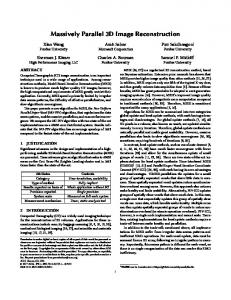
We implemented a 3D reconstruction system named SCRAPER. We experimentally reconstructed a part of a lecture room in the graduate school of informatics in Kyoto University. The target space is imaged by four SONY EVI-G2O video cameras fixed at the corners of the lecture room (Figure 2). Table 1 shows the camera position in the room coordinate system. In the experiment, we prepared four image c a p tors and four extractors, and used four SUN Ultra2 200MHz workstations for them. We prepared four 3D composers and assigned them to four SUN Ultra1 170MHz workstations. A scheduler runs on a different
1
Frame Image Captor
a Extractor
3DComposer
Figure 3: SOOS
Figure 1: Pipeline Architecture
Orlgln
z
Figure 2: Camera Layout in The Lecture Room
Figure 4: SOIS of Camera (d)
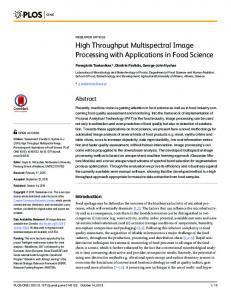
workstation. All the workstations are connected on a LAN. The scheduler makes a synchronization among the image captors, the extractors and the 3D composers via 100 base-T Ethernet and 155Mbps ATM LAN. The dynamic region data from the extractors to the 3D composers are transferred on ATM LAN. Figure 3 shows SOOS defined by the static object database given in advance. A SOIS from the camera (d) in Figure 2 is shown in Figure 4 for example. These subspace have been calculated before the SCRAPER system starts the reconstruction. The system reconstructed the the target space which was imaged more than three cameras. Hence, so a part of the target space - was observed by four cameras, and other part was observed by three cameras. In the case four cameras imaged the subspace, n in Equation (2) should be four, and in the other
case, if a camera j could not observe the subspace, U is the product of U;, (i = 1,2, . . , n, i # j). Figure 5 displays the target space which is visible by at least three cameras in the lecture room. In the experiment, the image captor takes images with the size of 320 x 240 pixels. The camera which locates the furthest position from the target space images a cubic subspace of 5 centimeters on a side in the target space onto one pixel in the captured image. Therefore, we set the voxel size as a cube of 5 centimeters on a side. The target space shown in Figure 5 corresponds to 96,769 voxels.
.
-
Table 1: Camera Position
Figure 5: Target Space
We conducted an experiment to measure the throughput and the latency of our prototype system. The target space is shown in Figure 5, and we put a box as a dynamic object whose size is 55cm x 55cm x 25cm. The result of using four 3D composers are shown in Table 2. A variable r indicates number of 3D composers served in each path and s indicates number of paths in the system. We also conducted an experiment with only one 3D composer just for comparison and its throughput is 2.2 fps and its latency is 1,384 msec. Table 2: Throughput And Latency 3D comp. per path : r Number of paths : s Latency [msec] Throughput [fps]
2 1 4 2 730 560 7.3 7.2
4 1 490 6.1
1 1 1,384 2.2
The required throughput and latency differ according to applications. One good feature of our method is that we can change the formation suitable to the applications by changing r and s. The result indicates that the case of two 3D composers at two paths is good because the throughput is almost same as four 3D composers a t one path and the latency is as short as that of the case of four paths. We implemented a virtual space viewer which displays the reconstructed real space as a set of voxels in realtime. This viewer displays not only the dynamic objects but also the static objects given to the system in advance, so a user can walk around the lecture room and observe the real-time real space from any viewpoint with little delay. An example of a captured image is shown in Figure 6 . Figure 7 shows the reconstructed space displayed by the viewer. The voxels displayed in the center corresponds to U ,which were transmitted from SCRAPER system.
4
Conclusion
We have presented the method of high speed 3D reconstruction in the situation the multiple cameras surround a certain real space. We showed that our approach introducing the division of the target space and the multiple paths in the pipeline architecture improves the throughput and the latency of the 3D reconstruction. With four 3D composers, SCRAPER achieved 7.2f p s with 560ms delay by using two paths and assigning two 3D composers at each path. We also implemented the virtual space viewer in which a user can observe the dynamic objects merged with the static objects from any viewpoint. We would like to extract the motion and the pose information from the reconstructed human shape in the future research.
Figure 6: Video Image from Camera (a)
Figure 7: IXeconstructed Space from Other Viewpoint
Acknowledgement This work has been partly supported by "Cooperative Distributed Vision for Dynamic Three Dimensional Scene Understanding (CDV)" project (JSPSRFTF96P00501, Research for the Future Program, the Japan Society for the Promotion of Science).
References [I] P.J.Narayanan, P.W.Rander, and T.Kanade: "Constructing Virtual Worlds Using Dense Stereo," Proc. Sixth IEEE ICCV, pp.3-10,1996. [2] J.E.Boyd, E.Hunter, P.H.Kelly, T.Li-Cheng, C.B.Phillips, and R.C.Jain, "MPI-Video infrastructure for dynamic environments," Proc. IEEE ICMCS, pp.249-254, 1998. 131 T.Kanade, A.Yoshida, K.Oda, H.Kano, and M.Tanaka, &AStereo Machine for Video-rate Dense Depth Mapping And Its New Applications," Proc. CVPR, pp.196-202, 1996. [4] K.Sato, A.Yokoyama, and S.Inokuchi, "Silicon range finder-a realtime range finding VLSI sensor," Proc. IEEE 1994 CIC, pp.339-342, 1994. [5] R.Raskar, G.Welch, M.Cutts,A.Lake,L.Stesin, and H.Fuchs, "The Office of the Future: A Unified Approach to Image Based Modeling and Spatially Immersive Displays," SIGGRAPH98 Annual Proc., pp.179-188, 1998.