IEICE TRANS. ELECTRON., VOL.E82–C, NO.2 FEBRUARY 1999
219
PAPER
Joint Special Issue on Photonics in Switching: Systems and Devices
High-Speed Multi-Stage ATM Switch Based on Hierarchical Cell Resequencing Architecture and WDM Interconnection∗ Seisho YASUKAWA†a) , Naoaki YAMANAKA† , Eiji OKI† , and Ryusuke KAWANO† , Members
SUMMARY This paper proposesd a non-blocking multistage ATM switch based on a hierarchical-cell-resequencing (HCR) mechanism and high-speed WDM interconnection and reports on its feasibility study. In a multi-stage ATM switch, cellbased routing is effective to make the switch non-blocking, because all traffic is randomly distributed over intermediate switching stages. But due to the multi-path conditions, cells may arrive out of sequence at the output of the switching fabric. Therefore, resequencing must be performed either at each output of the final switching stage or at the output of each switching stage. The basic HCR switch performs cell resequencing in a hierarchical manner when switching cells from an input-lines to a output-line. As a result, the cell sequence in each output of the basic HCR switch is recovered. A multi-stage HCR switch is constructed by interconnecting the input-lines and output-lines of these basic HCR switches in a hierarchical manner. Therefore, the cell sequence in each final output of the switching fabric is conserved in a hierarchical manner. In this way, cell-based routing becomes possible and a multi-stage ATM switch with the HCR mechanism can achieve 100% throughput without any internal speedup techniques. Because a large-capacity multi-stage HCR switch needs a huge number of high-speed signal interconnections, a breakthrough in compact optical interconnection technology is required. Therefore, this paper proposes a WDM interconnection system with an optical router arrayed waveguide filter (AWGF) that interconnects high-speed switch elements effectively and reports its feasibility study. In this architecture, each switch element is addressed by a unique wavelength. As a result, a switch in a previous stage can transmit a cell to any switch in the next stage by only selecting its cell transmission wavelength. To make this system feasible, we developed a wide-channel-spacing optical router AWGF and compact 10-Gbit/s optical transmitter and receiver modules with a compact high-power electroabsorption distributed feedback (EA-DFB) laser and a new bit decision circuit. Using these modules, we confirmed stable operation of the WDM interconnection. This switch architecture and WDM interconnection system should enable the development of highspeed ATM switching systems that can achieve throughput of over 1 Tbit/s. key words: ATM, non-blocking, multi-stage switch, WDM, interconnection
1.
Introduction
The rapid growth of Internet traffic and demands Manuscript received June 18, 1998. Manuscript revised September 16, 1998. † The authors are with NTT Network Service Systems Laboratories, Musashino-shi, 180-8585 Japan. a) E-mail:
[email protected] ∗ This paper is also published in IEICE Trans. Commun., Vol.E82-B, No.2, pp.271–280, February 1999.
for high-speed real-time-data services require a highspeed multimedia infrastructure. Asynchronous transfer mode (ATM) is a key technology for creating future multimedia networks that support these multimedia services [1]. The increasing demands for these services will require a switching system that can offer 1 Tbit/s throughput [2]. A multi-stage switch architecture is a feasible and cost-effective way to make such a system. A threestage Clos architecture is the best architecture in terms of switch scalability because it can be expanded easily using the same switching block, but it has two basic problems [3]–[5]. One is that if connection-based routing (in which all cells belonging to the same virtual channel (VC) take the same path through the multistage switch) is used, this architecture needs resource management in the switches in the intermediate stage to avoid overloading conditon caused by multiple VCs concentrating on the same output and exceeding its capacity. An effective way to eliminate the need for resource management in the intermediate stage is to use cell-based routing (in which cells belonging to the same VC may take different paths through the multi-stage switch). However, cell-based routing may cause some cells to arrive out of order at the output of the switching fabric. Therefore, a cell resequencing function is necessary to correct this cell sequence disorder. The second basic problem is that a huge number of highspeed signal interconnections are necessary for a highspeed multi-stage ATM switch. For example, N × N (full mesh) interconnection is necessary in the threestage Clos architecture. From the viewpoint of switch performance, it is better to use an I/O line speed of 10 Gbit/s for a Tbit/s ATM switch; however, the larger the switch size becomes, the more difficult it becomes to interconnect N × N unit switches in a feasible and cost effective manner. This paper proposes a non-blocking multi-stage ATM switch based on a hierarchical-cell-resequencing (HCR) mechanism. An HCR switch employs cell-based routing, so it needs to have a cell resequencing function. The basic HCR switch element is constructed from a crosspoint-buffer-type switch and each crosspoint in the basic HCR switch is interconnected in a hierarchical manner to the output. When both the upper and lower
IEICE TRANS. ELECTRON., VOL.E82–C, NO.2 FEBRUARY 1999
220
Fig. 1
Logical structure of three-stage HCR switch.
crosspoints have a cell to transmit, the HCR mechanism compares the time stamps in the internal cell headers, which indicates the times at which the cells were is sent to the HCR switch, and switches the cell having the smaller time stamp to the output. This time stamp comparison is repeated for every crosspoint in a hierarchical manner. Thus, a basic HCR switch performs cell resequencing and cell switching in a hierarchical manner at the same time. In a multi-stage HCR switch, each output of an HCR switch is interconnected with an input of the next stage’s HCR switch. As a result, a multi-stage hierarchical cell resequencing network can be constructed from these switches. Therefore, perfect cell resequencing is performed at each output of the multi-stage switching fabric and a multi-stage HCR switch can achieve 100% throughput without any internal speed-up techniques. From the implementation point of view, a highspeed N × N interconnection system is necessary to interconnect basic HCR switches. To make this multistage HCR switch system feasible, a compact interconnection technology is necessary. This paper proposes a high-speed WDM interconnection system and reports on a feasibility study of a 640-Gbit/s system. The proposed WDM interconnection system uses an N -channel optical router arrayed waveguide filter (AWGF) with perfect optical frequency periodicity. The study showed that N × N optical interconnection was achieved with only one optical router and N signal wavelengths. To make the 640-Gbit/s WDM interconnection system, we developed compact 10-Gbit/s optical transmitter and receiver modules and a wide-channel-spacing optical router AWGF. Using these modules, we demonstrated 640-Gbit/s WDM interconnection. The remainder of this paper is organized as follows. Section 2 presents the basic-HCR switch architecture and explains how to expand it to a multi-stage one. Switch performance is also reported. Section 3
describes the WDM interconnection system. Section 4 presents a prototype of the 640-Gbit/s WDM interconnection system and the 10-Gbit/s transmitter and receiver modules and optical router AWGF. Finally, Sect. 5 summarizes the key points. 2.
High-Speed Multi-Stage ATM Switch with Hierarchical Cell Resequencing Mechanism
2.1 Basic HCR Switch and Multi-Stage HCR Switch Design The logical structure of a three-stage HCR switch is shown in Fig. 1. This switch uses cell-based routing, and cell resequencinge is performed independently at each basic HCR switch by checking the time-stamps in the internal cell headers. To control the timestamps and the cell-switching-route, the multi-stage HCR switch has a time-stamp/routing-bit controller (TR-CNTL) at each of its inputs. This has a synchronous counter that is synchronized with the cell time and incremented by one during in each cell time, in order to control the time-stamps. When a cell enters the multi-stage HCR switch, the value of the synchronous counter is written in the header of the cell as a time-stamp. Thus, the time-stamp records the time at which the cell arrives at the multi-stage HCR switch and this time-stamp is used universally throughout the multi-stage HCR switch. When no cells enter the multi-stage HCR switch, TR-CNTL creates a dummy cell and the value of the synchronous counter is written in its header. The dummy cell informs the later basic HCR switches that no cell is arrived at the to multi-stage HCR switch at the time indicated by its time-stamp. This information is used for the sake of correct time comparison in basic HCR switches and to achieve a small cell transfer delay in a multi-stage HCR switch. The TR-CNTL also controls routing bits (RBs) in the internal cell header. The RBs indicate the
YASUKAWA et al: HIGH-SPEED MULTI-STAGE ATM SWITCH
221
Fig. 2
Basic HCR architecture with time-stamp-based cell sellection.
cell-switching-route that determines the second switch to use when switching a cell. The TR-CNTL cyclically change these RBs in synchronized with the cell time. This balances the load in the second switch, so no internal-speed-up technique is necessary to make the multi-stage HCR switch non-blocking. The basic HCR switch performs cell switching and resequencing at the same time in switch elements. Its block diagram is shown in Fig. 2. It uses a scalabledistributed-arbitration (SDA) scheme when it switches a cell to an output port [6], [7]. The basic HCR switch is a crosspoint-buffer-type switch. Each crosspoint is constructed from a crosspoint buffer, a transit buffer, an arbitration-control part (CNTL), and a selector. A crosspoint buffer sends a request (REQ) to CNTL if it has at least one cell stored in it. Likewise, the transit buffer also sends REQ to CNTL if it has at least one cell stored in it. A transit buffer stores several cells that are sent from either the upper crosspoint buffer or the upper transit buffer. If the transit buffer is full, it sends a not-acknowledgment (NACK) to the nextupper CNTL. When this upper CNTL receives a NACK signal, it stops sending cells to the lower transit buffer. If a CNTL does not receive NACK from the next lower transit buffer, it selects a cell to transmit within one cell time. The upper-most CNTL always selects a cell in the crosspoint buffer because the upper-most crosspoint does not have a transit buffer. Then the selected cell is sent through a selector to the next lower transit buffer or to the output line in the lowest selector. The cell selection is performed according to a timestamp-based cell selection rule, which determines which cell should be sent as follows. Case 1: If either the transit buffer or the crosspoint buffers has no cells to transmit, all of the CNTLs stop selecting a cell to transmit to avoid causing cell sequence disorder in the switch. Case 2-1: If both the crosspoint and transit buffers
have cell that is not a dummy cell to release, the cell with the smaller time stamp is selected. If the time stamp of the cell in the crosspoint buffer equals that in the transit buffer, CNTL determines which cell should be transmitted using a second cell selection rule [7]. Let us consider the k-th crosspoint and transit buffer from the top. The second rule is that the k-th crosspoint buffer is selected with probability 1/k, while the k-th transit buffer is selected with probability (k − 1)/k because the k-th transit buffer is interconnected with k − 1 upper crosspoints, so the probability (k − 1)/k represents cell transmission from k − 1 upper crosspoints. Using this second cell selection scheme, this switch can fairly select a cell to transmit when both cells have equal time stamp values. Case 2-2: If the crosspoint buffer has at least one cell to transmit and the transit buffer has a dummy cell, the cell with the smaller time stamp is selected. If the time stamp of the cell in the crosspoint buffer equals that of the dummy cell in the transit buffer, CNTL selects the cell in the crosspoint buffer for transmission because this cell has a high priority. Case 2-3: If the transit buffer has at least one cell to transmit and the crosspoint buffer has a dummy cell, the cell with the smaller time stamp is selected. If the time stamp of the cell in the transit buffer equals that of the dummy cell in the crosspoint buffer, CNTL selects the cell in the transit buffer for transmission because this cell has a high priority. In the above queuing processes, if either crosspoint buffer or transit buffer or both buffers have a dummy cell, then they do not treat it as the tail of the queue, and a transit buffer that has a dummy cell does not send a NACK signal to the upper CNTL. Therefore the dummy cell in the crosspoint buffer or transit buffer is overwritten by a new cell coming from the previous HCR switch’s output or upper CNTL to avoid an excessive increase in load.
IEICE TRANS. ELECTRON., VOL.E82–C, NO.2 FEBRUARY 1999
222
In this way, the basic HCR switch performs cell resequencing at each crosspoint in a hierarchical manner. The concept of cell resequencing is also shown in Fig.2. After switching, the upper input lines are concentrated one-by-one to lower input lines until the final output line. When two lines are concentrated into one line, cell resequencinge is performed by the timestamp-based cell selection algorithm. As a result the cell sequence is conserved at each output of the basic HCR switch. We can expand the switching capacity by interconnecting several basic HCR switches in a multi-stage manner. A three-stage HCR switch architecture is most attractive from the viewpoint of switch scalability. To achieve non-blocking operation without any internal speed-up techniques, cell-based routing is necessary. Thus incoming cells are distributed over switches in the second stage to balance the traffic load of the second stage. As a result, cells belonging to the same VC may take different routes through this switching network, which may cause cell sequence disorder. To avoid cell sequence disorder, this basic HCR switch is interconnected in a hierarchical manner in a three-stage HCR switch. This means that each basic HCR’s output is connected to the input of the next stage’s basic HCR. Therefore, a larger multi-stage HCR network can be constructed. Because cell resequencing is performed in a hierarchical manner in each stage in this architecture, the cell sequence is perfectly conserved at each output of the three-stage HCR switch. In this way, switching and cell resequencing are performed at the same time in the multi-stage HCR switch. 2.2 Performance of HCR Switch We evaluated the performance of the HCR switch in terms of average cell transfer delay time by computer simulation. We assumed a three-stage HCR switch (switch size: 64 × 64) that is composed of basic HCR switch elements (switch size: 8 × 8). We also assumed that cell arrivals at each input ports follows a Bernoulli process. When the input traffic load is ρ, an incoming cell arrives with probability ρ, during one cell time. And the probability of no cell arriving is 1 − ρ. The input traffic is assumed to be homogenous and it is distributed uniformly among all input ports. And the destinations of incoming cells are distributed uniformly among all output ports. Figure 3 shows the average cell transfer delay performance of the basic HCR switch and of the three-stage HCR switch. The more the offered load increases, the more the average cell transfer delay increases. This delay performance is identical to the conventional performance of an output-buffer-type switch except for an excess delay time due to the cell resequencing function in the basic HCR switch. This delay time depends on the number of resequencing-steps in the basic HCR switch. In this simulation, we as-
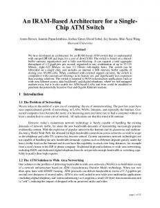
Fig. 3
Average delay performance of HCR switch.
sumed a single-stage HCR network having 7-step timecomparison and a three-stage HCR network having 21step time-comparison. Therefore, 7 excess cell times and 21 excess cell time are added to the conventional output-buffer-type switch. These results show that a multi-stage HCR switch can achieve 100% throughput and that its delay performance is identical to outputbuffer switches connected in series, excluding the cell resequencing delay. Grouping crosspoint buffers and reducing the number of transit buffers in the basic HCR switch can reduce the resequencing delay. In this architecture, two-phase time-stamp comparison is performed. First, the time-stamps of grouped-crosspoint are compared. When a crosspoint that has a cell having the smallest time-stamp is selected, this crosspoint sends the cell to a lower transit buffer. In the lower crosspoint, the same time-stamp comparison is performed and CNTL compares the time-stamps of cells in the transit buffer and crosspoint buffer. Then resequencing is performed using the time-stamp-based cell selection algorithm mentioned earlier before. Figure 3 also shows the delay performance results for a basic grouped (g = 4) HCR switch. In this example, four crosspoint buffers were grouped, and the time-stamp comparison was performed for this group. This grouping reduced the number of transit buffers from 7 to 1. As a result, the average resequencing delay time was reduced from 7 to 1. Using this technique we can construct a multi-stage HCR switch that has a smaller cell transfer delay. 3.
WDM Interconnection System with Optical Router
A multi-stage HCR switch is scalable. However, it needs a high-speed N ×N interconnection system to in-
YASUKAWA et al: HIGH-SPEED MULTI-STAGE ATM SWITCH
223
Fig. 4
WDM interconnection.
terconnect N basic HCR switches (switch size: N ×N ). In this case, the conventional interconnection system, which uses discrete structures such as high-speed coaxial cables, becomes impractical when N approaches ten. The number of intersections in interconnection that must be handled per stage is N 2 , which in this case is 100. Therefore, combining wide-bandwidth optical technologies and high-speed electronics technologies will be the key to overcoming the throughput limitation of electrical ATM switch systems [8]–[10], because optical interconnection technology offers a breakthrough in transmission distance, electromagnetic interference, I/O pin area, and so on. To make an optical interconnection system feasible, we need a compact optical interconnection system that can handle a large number of high-speed intersections. As a step toward creating a Tb/s multi-stage HCR ATM switch system, we propose a WDM interconnection system that interconnects electrical basic HCR switches [11], [12]. Figure 4 shows our proposed WDM interconnection system. This architecture uses N different wavelengths and an N × N optical router to interconnect N basic switches (N × N ) through an optical router [12]. The optical router enables every basic switch in the front stage to address every switch in the next stage by using a different wavelength. For example, a 640-Gbit/s WDM interconnection architecture uses eight different wavelengths to interconnect 80Gbit/s basic HCR switches through an 8 × 8 optical router. Every 80-Gbit/s basic HCR switch in the front stage can address every 80-Gbit/s switch in the next stage by using a different wavelength. The proposed WDM interconnection system is composed of eight transmitter (TX) blocks, one op-
tical router, and eight receiver (RX) blocks. Each TX block is composed of eight 10-Gbit/s optical TX modules, having eight optical sources with different wavelengths, and one optical multiplexer. And each TX block transmits a wavelength-multiplexed 8 × 10Gbit/s WDM signal. Each RX block is composed of one optical demultiplexer and eight 10-Gbit/s optical receiver modules. And each RX block receives a wavelength-multiplexed 8 × 10-Gbit/s WDM signal. The optical router at the center of these modules is composed of an AWGF. This works as an optical router because its free spectral range is eight times the channel spacing. This means that this optical router switches input WDM optical signals to different output ports depending on their wavelength. And the routing relationship between the output channel number and wavelength depends on the input channel number to which the WDM optical signal is introduced. This is done in a cyclic manner as shown in Fig. 4. Thus, a basic HCR switch in the front stage can switch a cell to any basic HCR switch in the next stage using different wavelength optical signals. Thus, this 8 × 8 interconnection can achieve 80-Gbit/s, 8-WDM throughput. Furthermore, each electronic basic HCR switch is interconnected via a signal of a different wavelength. From the system point of view and switch scalability, it is better for the operating clock of each unit switch to be independent. Therefore, we prepared an independent clock-data-recovery (CDR) circuit based on a phase-locked loop (PLL) in each 10Gbit/s highway. They compensate for the phase differences between different 10-Gbit/s highway data. As a result, we obtained stable cell transmission between basic switches in different stages.
IEICE TRANS. ELECTRON., VOL.E82–C, NO.2 FEBRUARY 1999
224
This novel system reduces the number of discrete optical fibers needed and makes system simple to operate and can achieve a total system throughput of 640 Gbit/s using only one optical router. 4.
Prototype System of WDM Interconnection
4.1 Wide-Channel-Spacing WDM To introduce WDM technology into switch interconnection, the WDM interconnection system must be simple. The conventional WDM system uses narrow-channelspacing WDM, because this increases transmission capacity and reduces optical loss in a long fiber transmission line. But this requires strict wavelength control, which makes the WDM system complicated and reduces the system’s temperature margin. It is better to widen the passband of the AWGF to attain a wide temperature margin and eliminate the complex temperature control circuits. But a wide AWGF passband causes a large frequency error in the optical router, so wide WDM channel spacing increases the difficulty of selecting optical sources. Considering these problems, we designed our system to use an AWGF with a wide channel spacing of 525 GHz (center: 193.1 THz (1552.5 nm)). To select the optimal channel condition, we must make the filter loss and frequency error small. Figure 5 shows its loss spectra. The passband of this AWGF (160 GHz) is much wider than that of the conventional AWGF (20–30 GHz). This means that this system can tolerate a temperature range seven times as wide as that of a conventional system, so its temperature circuits can be simpler. As a result, the total system size can be dramatically reduced. 4.2 Small 10-Gbit/s Transmitter/Receiver Modules The proposed WDM interconnection system uses a 64byte ATM cell format. In the WDM interface, 64-byte ATM cells are mapped into a single 10-Gbit/s optical data signal and in the switch interface 64-byte ATM cells are mapped into eighteen 622-Mbit/s datalines (16: data × 32 cycles, 2: frames) and two 622-MHz clock lines. To achieve stable optical transmission, the basic HCR switch has coders and decoders in order to maintain the equilibrium of the signal in the payload of ATM cells in 10-Gbit/s format. Figure 6 shows an external view of our new transmitter and receiver modules. Both modules are the same size: 80 × 120 × 20 mm. This is about onetwentieth the size of the conventional module [13]. These modules each have a high-speed multi-channel connector and can easily be connected to another board. Figure 7 shows the appearance and block diagrams of the transmitter and receiver modules. Both modules consist of a 10-Gbit/s-class high-frequency
Fig. 5 Transmission loss spectrum of wide-channel-spacing AWGF.
Fig. 6 External view of transmitter/receiver module and new cooling structure.
printed wiring board (PWB) and a 622-Mbit/s-class low-frequency PWB. In the transmitter and receiver modules, the high- and low-frequency boards are arranged face to face and connected with a fine coaxial cable. These modules have power dissipation of 9.65 and 22.5 W, respectively. Instead of a conventional radiation fin, a heat pipe is used to conduct heat from the heat source to a fin inside the duct on the end of module. Then it is radiated away by push-pull microfans. The heat-pipe structure embedded in the substrate of the module is shown in Fig. 6. Using this cooling method, we can fit the 10-Gbit/s optical transmitter and receiver functions into a size of 80 × 120 × 20 mm each with stable operation. The transmitter uses one silicon bipolar IC, a 16 : 1 multiplexer. This multiplexer IC receives a low speed (622-Mbit/s × 16) ATM cell datastream and performs bit-multiplexing to convert sixteen 622-Mbit/s ATM cell datastreams into one a 10-Gbit/s ATM cell datastream. In this conversion, it compares the phase difference between the input 622-MHz CLK and the divided 622-MHz CLK from the 10-GHz VCO in the
YASUKAWA et al: HIGH-SPEED MULTI-STAGE ATM SWITCH
225
Fig. 7
Appearance and block diagrams of 10-Gbit/s transmitter/receiver module.
phase-locked loop. Thus it can latch 622-Mbit/s input data of arbitrary phase at optimum phase conditions and can multiplex 16 such streams into the 10-Gbit/s data waveform. To obtain a clear eye pattern with an EA-DFB laser, a DFF IC reshapes the 10-Gbit/s data. This DFF IC can attain an output rise time of 40 ps and an output fall time of 30 ps. Following this IC, a modulator driver circuit having GaAs FETs amplifies the signal voltage swing up to 3 Vp−p , which is applied to the multiple quantum well (MQW) optical modulator of EA-DFB laser. To adjust the extinction characteristics of the modulator wavelength dependency, the driver output is connected to a bias circuit, which can apply optimum bias to the MQW modulator. The output waveform from the EA-DFB transmitter module is shown in Fig. 8. A clear eye pattern was obtained and average optical output power of over 3 dBm was achieved. In the receiver module, a transimpedance-type preamplifier is packaged together with a PIN-PD. Even though this module is very compact, it can achieve an 8-GHz bandwidth with 52-dBΩ gain. A post-amplifier MCM amplifies the input signal to the SCFL (0: −1 V) level. This MCM is composed of a post-amplifier IC and a limiting amplifier IC. These ICs are fabricated using GaAs MESFETs. The post-amplifier IC amplifies the input signal linearly and achieves a 16-dB gain at 8 GHz. The limiting amplifier IC achieves a 0.8Vp−p output signal at 10 Gbit/s. Clock data recovery is then done by the PLL circuit, which is composed of a decision circuit with a phase comparator and an external low-pass filter and VCO. In this PLL circuit, the phase comparator is made from an EXOR circuit, which compares the phase difference between the raw
Fig. 8 10-Gbit/s optical output waveform and output waveform of ATM cell interface LSI.
input data and the data output from the decision circuit. The phase error signal is fed back to the VCO via the low-pass filter. Therefore this system can perform perfect clock-data-recovery from an input signal with arbitrary phase. This PLL circuit has a temperaturecompensation circuit and can offset the VCO frequency error, which depends on temperature. Thus this mod-
IEICE TRANS. ELECTRON., VOL.E82–C, NO.2 FEBRUARY 1999
226
Fig. 9
Overview of optical routing board and system image of three-stage HCR switch.
ule performs stable clock data recovery at junction temperatures up to 70 degrees C. In the 1 : 16 demultiplexer IC, bit-demultiplexing is performed and sixteen 622Mbit/s datastreams and one 622-Mbit/s clock are demultiplexed from the 10-Gbit/s data. Then 16 signals are introduced into the ATM cell interface synchronization (wordsync) IC, which is fabricated using silicon bipolar technology. This IC protects the ATM cell interface between the basic HCR switch and WDM interconnection. Using this wordsync IC, 10-Gbit/s optical signal interconnection is achieved without considering the ATM cell format because this IC searches for an 8bit cell synchronization pattern from 16 input-datalines every 32 cycles. Once it finds one in its input datalines, this IC calculates its shift from the ideal ATM cell format and regenerates the ATM cell signal and the frame pulse that indicates the head of the cell. This IC has a triple error protection function, which allows it to ignore a frame error caused by signal jitter until it has detected the error three times. This mechanism enables stable pattern matching and transparent ATM cell transmission between basic HCR switches. Figure 8 also shows the 622-Mb/s ATM cell waveform of the wordsync LSI. Transparent ATM cell transmission is confirmed. 4.3 System Performance Using these modules, we demonstrated the 640-Gbit/s WDM optical interconnection system. Figure 9 shows an overview of our newly developed optical routing board and illustrated the three-stage HCR switch with WDM interconnection. In this system each switch module is attached to the backboard and interconnected with the optical router via a different wavelength. To achieve stable WDM interconnection, we achieved average optical output power (markratio=1/2) of over 3 dBm and receiver sensitivity of −16.5 dBm at a bit error rate of 10−11 (PRBS: 23 N). Using these modules, we can consider a wide optical power level diagram having about 20-dB optical power difference between the front and end of the WDM in-
terconnection system. This optical level margin exceeds the AWGFs loss, which is the sum of each loss at the multiplexer AWGF, router AWGF, and demultiplexer AWGF. As a result, we could construct WDM interconnection without using an optical amplifier. This also simplifies the WDM interconnection system. Moreover, thanks to the sufficient optical power margin and the wide-channel-spacing AWGF, the developed system showed stable operation over a wide temperature range. 5.
Conclusion
This paper proposed a high-speed multi-stage ATM switch called a hierarchical cell resequencing (HCR) ATM switch architecture and WDM interconnection architecture. To be non-blocking, the multi-stage HCR switch uses cell-based routing. Even though cell-based routing could cause cell sequence disorder at the output of the switch fabric, each basic HCR switch performs cell resequencing at its crosspoint in a hierarchical manner and conserves the cell sequence order at its output. A hierarchical cell resequencing network is used to construct a multi-stage HCR switch. Therefore, a multi-stage HCR switch performs perfect cell resequencing at each output of the switching fabric. As a result, a multi-stage HCR ATM switch achieves 100% throughput performance at any input traffic pattern without any internal speed-up techniques. Computer simulation results show that this architecture has similar cell transfer delay performance to a conventional output-buffer-type switch; the only difference is the resequencing delay in the basic HCR switch, but this can be reduced by grouping crosspoints in the basic HCR switch. We also proposed a WDM optical interconnection system to interconnect a huge number of high-speed signal effectively using WDM technology and optical routing technology. Using these technology, we can construct N × N interconnections with only one optical router AWGF. To confirm the system’s feasibility, we developed a 640-Gbit/s WDM interconnection system. This system uses eight wavelengths, each carrying
YASUKAWA et al: HIGH-SPEED MULTI-STAGE ATM SWITCH
227
a 10-Gbit/s signal, and 8×8 optical routers to avoid the interconnection limitation. To eliminate complex temperature control circuits, we used wide-channel-spacing WDM technology. Broadening the channel spacing to 525 GHz, compared with the conventional spacing of 70–100 GHz, raised the system’s temperature margin about by seven times compared with the conventional system. This dramatically reduced the temperature control circuits and eliminated the need for strict laser selection. Fully integrated 10-Gbit/s optical transmitter and receiver modules were produced using MCM technology and an EA-DFB laser. These small modules are only 80 × 120 × 20 mm each. Using them we demonstrated stable operation of 640-Gbit/s WDM interconnection on the ATM cell level over a wide temperature range and confirmed its feasibility on the system level. The proposed multi-stage HCR ATM switch and WDM interconnection system is applicable to future broadband ATM networks.
[13] A. Noda, K. Takahashi, T. Isogai, T. Ikeuchi, I. Yoneda, M. Sasagawa, C. Konishi, and S. Fujita, “Fully integrated 10Gbit/s optical transmitter module and receiver module,” Proc. 21st ECOC, pp.669–672, 1995.
References
Naoaki Yamanaka was born in Sendai-city, Miyagi Prefecture, Japan, on July 22, 1958. He graduated from Keio University, Japan where he received B.E., M.E. and Ph.D. degrees in engineering in 1981, 1983 and 1991, respectively. In 1983 he joined Nippon Telegraph and Telephone Corporation’s (NTT’s) Communication Switching Laboratories, Tokyo, Japan, where he was engaged in research and development of a high-speed switching system and high-speed switching technologies such as ultra-high-speed switching LSI, packaging techniques and interconnection techniques for Broadband ISDN services. Since 1989, he has been active in the development of Broadband ISDN based on ATM techniques. He is now researching future ATM based broadband ISDN architecture, and traffic management and performance analysis of ATM networks. He is currently a senior research scientist, supervisor, distinguished technical member in Broadband Network System Laboratory at NTT. Dr. Yamanaka received Best of Conference Awards from the 40th and 44th IEEE Electronic Components and Technology Conference, TELECOM System Technology Prize from the Telecommunications Advancement Foundation, two times of IEICE Switching System Research Award and IEEE CPMT Transactions Part B: Best Transactions Paper Award in 1990, 1994, 1994, 1996, 1998 and 1996 respectively. Dr. Yamanaka is Broadband Network Area Editor of IEEE Communication Surveys, Associate Editor of IEICE Transaction, IEICE Communication Society International Affairs Director as well as Secretary of Asia Pacific Board at IEEE Communications Society. Dr. Yamanaka is a senior member of IEEE.
[1] H. Ishikawa, “Evolving from narrowband,” IEEE Commun. Mag., vol.30, no.8, pp.32–36, 1992. [2] N. Yamanaka, S. Yasukawa, E. Oki, T. Kawamura, T. Kurimoto, and T. Matsumura, “OPTIMA: Tb/s ATM switching system architecture based on highly statistical optical WDM interconnection,” Proc. IEEE ISS’97, Systems Architecture, 1997. [3] R. Melen and J.S. Turner, “Non-blocking networks for fast packet switching,” Proc. IEEE Infocom’89, pp.548–557, 1989. [4] M. Collivignarelli, A. Daniele, G. Gallassi, F. Rossi, G. Valsecchi, and L. Verri, “System and performance design of the ATM node UT-XC,” Proc. ICC’94, 1994. [5] K.Y. Eng, M.J. Karol, and Y.S. Yeh, “A growable packet (ATM) switch architecture: Design and application,” IEEE Trans. Commun., pp.423–230, 1992. [6] E. Oki and N. Yamanaka, “A high-speed ATM switch based on scalable distributed arbitration,” IEICE Trans. Commun., vol.E80-B. no.9, pp.1372–1376, 1997. [7] E. Oki and N. Yamanaka, “Scalable crosspoint buffering ATM switch architecture using distributed arbitration scheme,” Proc. IEEE ATM’97 Workshop, pp. 28–35, 1997. [8] E. Munter, J. Parker, and P. Kirkby, “A high-capacity ATM switch based on advanced electronic and optical techniques,” IEEE Commun. Mag., pp.64–71, 1995. [9] M. Eiseh, G. Grosskopf, R. Ludwig, W. Pieper, and H.G. Weber, “Photonic ATM switching with semiconductor laser amplifier gates,” Electron. Lett., vol.28, no.15, pp.1438– 1439, 1992. [10] M. Tsukada, A. Misawa, J. Nishikido, Y. Shimazu, and H. Nakano, “Experiments on photonic cell switching with an optical input buffer,” Electron. Lett., vol.30, no.13, pp.1081–1082, 1994. [11] C.A. Brackette, “Dense wavelength division multiplexing networks: Principles and applications,” J. Sel. Areas Commun., vol.8, pp.948–964, 1990. [12] H. Takahashi, K. Oda, H. Toba, and Y. Inoue, “Transmission characteristics of arrayed waveguide N × N wavelength multiplexer,” IEEE J. Lightwave Tech., vol.13, no.3, pp.447–455, 1995.
Seisho Yasukawa received the B.E. and M.E. degrees from the University of Tokyo, Tokyo, Japan, in 1993 and 1995, respectively. In 1995, he joined Nippon Telegraph and Telephone Corporation’s (NTT’s) Network Service Systems Laboratories, Tokyo, Japan. He is currently researching a high-speed ATM switching system and optical interconnection system for future multimedia communication network based on ATM techniques.
IEICE TRANS. ELECTRON., VOL.E82–C, NO.2 FEBRUARY 1999
228
Eiji Oki received the B.E. and M.E. degrees from Keio University, Yokohama, Japan, in 1991 and 1993, respectively. In 1993, he joined Nippon Telegraph and Telephone Corporation’s (NTT’s) Communication Switching Laboratories, Tokyo, Japan. He is currently researching future multimedia communication network architecture based on ATM techniques, traffic control issues of ATM networks, and high-speed ATM switching system at NTT Network Service Systems Laboratories as a Research Engineer. He received IEICE Switching System Research Award in 1998. He is a member of IEEE Communication Society.
Ryusuke Kawano was born in Oita, Japan, on April 2, 1964. He received the B.S. and M.S. degrees from University of Osaka Prefecture in 1987 and 1989. In 1989 he joined Nippon Telegraph and Telephone Corporation (NTT) and began researching and developing process technology for high-speed Si-bipolar devices. Since 1992 he has been engaged in researching and developing high-speed integrated circuits using Si bipolar transistors and GaAs MESFETs at the NTT LSI Laboratories, Kanagawa, Japan. After moved to NTT Network Service Systems Laboratories, Tokyo, Japan, his current research interests includes very large capacity ATM swithing hardware such as high-speed logic, optical interconnection and cooling. Mr. Kawano is a member of IEEE.