Discriminate Analysis (LDA) that minimizes the discrimination within a class and maximizes ... tone based face detection for face segmentation. Skin is a widely ...
SIGNAL PROCESSING
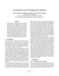
Histogram Based FACE Gholamreza Anbarjafari of the Department of Information System Engineering at the Cyprus International University, Turkey, and Hasan Demirel of the Department of Electrical and Electronic Engineering at the Eastern Mediterranean University in North Cyprus, Turkey, describe a practical face recognition system based on colour histogram matching IN THE RECENT DAYS, security systems take a very important place in our lives. In this work a practical face recognition system based on colour histogram matching is proposed. Histogram matching is performed by using the correlation between the histograms of a given face and the histograms of the faces in the database. The high correlation between the histograms of the same faces at different resolutions makes the system robust to scale changes. A graphical user interface is developed in MATLAB environment for establishing links between project components. A biometric system provides automatic recognition of an individual based on some unique characteristic owned by the individual. Biometric systems have been developed based on fingerprints, hand geometry and the face. The earliest work in computer recognition of faces is reported by Bledsoe. Kanade used a method of characterizing the face by geometrical parameterisation, whereby distances and angles between points are used. Statistical face recognition systems, such as the Principal Component Analysis (PCA) based eigenfaces method introduced by Turk and Pentland attracted a lot of attention by researchers. Relhumeur et al introduced the fisherfaces method, which is based on the Linear Discriminate Analysis (LDA) that minimizes the discrimination within a class and maximizes the discrimination between classes. Another statistical descriptor can be considered to be the histogram of a gray level image which shows the distribution in terms of occurrence frequencies of gray level pixel intensities. Histogram of a face image can be considered as the signature of the face, which can be used to represent the face image in a low dimensional space. Images with small changes in translation, rotation and illumination still possess
Figure 1: Original image
20
❙ December 09 - Electronics World
Figure 1: Detected skin region
high correlation in their corresponding grey-scale histograms. This histogram characteristic prompts the idea of using not only the greyscale histograms but also colour histograms for face recognition. Yoo et al used chromatic histograms as a model of faces to perform face detection. Ojala et al divided a face into several blocks and then the Local Binary Pattern (LBP) feature histograms are extracted from each block and concatenated into a single global feature histogram which efficiently represents the face image. The recognition is performed by simple distance-based histogram matching. In our previous work, we have introduced a probability distribution function based face recognition system the using Kullback- Leibler distance.
Pre-Processing: Skin-Tone Detection Method Face segmentation is one of the important pre-processing phases of face recognition. There are several methods for this task such as skin tone based face detection for face segmentation. Skin is a widely used feature in human image processing with a range of applications. Human skin can be detected by identifying the presence of skin colour pixels. Many methods have been proposed for achieving this. Chai and Ngan modelled the skin colour in the YCbCr colour space. Boussaid et al modified Chai and Ngan’s methods in order to make it VLSI friendly. They normalized the RGB components and skin colour was detected by using four threshold values, forming a rectangular region in new RGB space. In the present work the detection is done by using the HSI colour space, since hue, saturation and intensity are three properties used to describe colour. The advantage of using the HSI colour space is its
Figure 3: Skin region image after opening
Figure 4: Detected skin region
SIGNAL PROCESSING
RECOGNITION SYSTEM
Figure 5: Image where the skin region of the original image has been segmented
Figure 6: Image where the skin region of the original image has been segmented
independency to know the exact percentage of red, green or blue to produce a colour. Many applications such as machine vision use the HSI colour space in identifying the colour of different objects. Kjeldson and Kender have stated a colour predicate in the HSI colour space to distinguish skin regions from other segments. Skin colour classification in the HSI colour space is based on hues and saturation values. In this article the threshold for hue and saturation has been found by using 450 face samples from the FERET dataset and 1500 face samples from the Essex University database. According to these samples, the thresholds for hue and saturation to satisfy recognition of skin are: (H < 0.17 or H > 0.63) and S > 0.1
(1)
According to thresholds mentioned before, the skin area of an image from the FERET database in Figure 1 has been detected and shown in Figure 5. Figure 2 shows the skin region of the given face. This image needs to be cleaned as there are some small pixels that have been detected in the skin region but are not necessary in being considered for the face recognition. By using opening operation on the binary image shown in Figure 2, a cleaner image shown in Figure 3 will be obtained. To include the nose holes and eyes, the region has been filled (see Figure 4). This binary image has been used as a mask to segment the original image to obtain the skin region, and ignoring the background and shadow effect for face recognition. In this article, each image, before being used for the recognition, has been pre-processed by this algorithm, and the face section has been segmented out for recognition.
PCA and LBP-based Face Recognition The eigenfaces method is based on linear PCA where a face image is
Figure 7: A pre-processed face image from HP database (a) with its subimages (b) where have been used for obtaining the LBP recognition rate
encoded to a low dimensional vector. All face images are decomposed into a small set of characteristic feature images called eigenfaces. Each face image is projected on the subspace of meaningful eigenfaces (ones with nonzero eigenvalues). Hence, the collection of weights describes each face. Recognition of a new face is performed by projecting it on the subspace of eigenfaces and then comparing its weights with the corresponding weights of each face from a known database. Assuming that all face images in a database are of the same size w×h, eigenfaces are obtained as the eigenvectors of the covariance matrix of the data points. Let Γi is an image from a collection of M images in a database. A face image is a 2-dimensional array of size w×h, where w and h are the width and height of the image, respectively. Each image can be represented as a vector of dimension w×h and the average image, Ψ, is defined as:
Each image Гi differ from the average image Ψ by the vector:
The covariance matrix of the dataset is defined as:
Since there are M images in the database, the covariance matrix C has only M-1 meaningful eigenvectors. Those eigenvectors ul can be obtained by multiplying eigenvectors vl, of the matrix L = ΛTΛ (of size M×M) with difference vectors in matrix Λ. www.electronicsworld.co.uk
❙
21
SIGNAL PROCESSING
The eigenvectors, ul, are called the eigenfaces. Eigenfaces with higher eigenvalues contribute more in representation of a face image. The face subspace projection vector for every image is defined by:
Figures 7a and 7b show one the pre-processed face images from the HP database and its sub-images in the I colour channel. Tables 3 and 4 show the performance of an LBP-based face recognition system, using the HP and the FERET face databases in the HSI and YCbCr colour spaces. LBP is a time consuming process compared to the proposed algorithm which has been discussed in the next section
Histogram-Based Pose Invariant Face Recognition
The projection vectors are indispensable in face recognition tasks, due to their uniqueness. The projection vector, which represents a given face image in the eigenspace, can be used for the recognition of faces. Euclidian distance, ε, between the projection vectors of two different images (Ω1 and Ω2) is used to determine whether a face is recognized correctly or not.
While for a perfect reconstruction of the face image all the coefficients may be needed, for recognition only the most significant coefficients play an important role. A typical face image which has been used for PCA is shown in Figure 6. PCA also has been applied to the different colour channels (H, S, I, Y, Cb and Cr). Table 1 and 2 show the performance of PCA-based face recognition system using data from the HP and the FERET face database in the HSI and YCbCr colour spaces respectively. In this article we have suggested to use the majority voting (MV) technique to consider the votes of each colour channel in a PCA-based face recognition system. For the LBP approach the pre-processed image has been divided into 64 sub-images and then the histograms of each sub-image in different colour spaces have been concatenated and used for recognition.
The histogram of an image is a statistical description of the distribution in terms of occurrence frequencies of pixel intensities. It can be considered as a feature vector representing the image in a lower dimensional space. The size of the image histogram depends on the number of quantization levels of the pixel intensities. A typical monochrome image with 8-bit representation has 256 grey levels. In a general mathematical sense, an image histogram is simply a mapping η i that counts the number of pixel intensity levels that fall into various disjoint intervals, known as bins. The bin size determines the size of the histogram vector. In this article the bin size is assumed to be 256 and the size of the histogram vector is 256. Given a monochrome image, a histogram η i meets the following conditions, where N is the number of pixels in an image:
Then, histogram feature vector, H, is defined by:
The similarity between two images can be measured by using the cross correlation between the histograms of the respective images. Cross correlation is a standard method of estimating the degree to which two vectors are correlated. Given to histogram vectors x(i) and y(i), where i=0, 1, 2...β-1 and β is the number of bins. The cross correlation vector r(t) is defined as:
Figure 8: Two subjects from HP database with 2 different poses (a), their segmented faces (b) and their histograms in Y (c), Cb (d), Cr (e), Hue (f), Saturation (g), and Intensity (h) colour channels respectively.
22
❙ December 09 - Electronics World
SIGNAL PROCESSING
where μx and μy are the means of the corresponding vectors and t is the translation. The denominator in this expression serves to normalize the correlation coefficients such that 0 ≤ r ≤ 1, where 1 is indicating maximum correlation and 0 indicating no correlation. The maximum correlation coefficient in the correlation vector is taken as the measure of similarity and used in the histogram matching process. Let the histograms of a set of training face images be H1, H2…HM, where M is the number of image samples. Then, a given query face image, the histogram of the query image Hq, can be used to calculate the correlation between Hq and histograms of the images in the training samples as follows: χi=max(Hi o Hq ) ,i= 1,L,M
Table 1: Performance of the PCA based system in H, S, I, Y, Cb and Cr colour channels of the HP face database.
(11)
Table 2: Performance of the PCA based system in H, S, I, Y, Cb and Cr colour channels of the FERET face database.
Here χi is the maximum cross correlation coefficient reflecting the similarity of the ith image in the training set and the query face. The, image with the highest similarity measure is declared to be the identified image in the set. Figure 8 shows two subjects with two different poses and their segmented faces from the HP face database. The images also have different backgrounds, with slight illumination variation. The intensity of each image has been equalized to minimise the illumination effect, where the shapes of the histograms are more or less preserved, while only the amplitudes are changing. The colour histograms used in the proposed system are generated only from the segmented face and, hence, the effect of the removed background regions is eliminated.
Table 3: Performance of the LBP based system in H, S, I, Y, Cb and Cr colour channels of the HP face database.
The performance of the proposed histogram-based face recognition system is tested on the HP and the FERET face databases, where there are 15 and 50 subjects with 10 varying poses and backgrounds. The colour faces in that dataset are converted from RGB into HSI and YCbCr and the dataset is divided into training and test sets. In this setup the training set contains n images per subject and the rest of the images (10-n) for the test set. The correct recognition rates in percentages of the HP and the FERET face databases are shown in Tables 5 and 6. Each result is the average of 100 runs, where we have randomly shuffled the faces in each class. It is important to note that the performance of each colour channel is different, which means that a person can be recognized in one channel, whereas the same person may fail to be recognized in another channel This observation prompts the idea of combining the results of different colour channels, which may increase the probability of making the correct recognition of a face image.
Majority Voting vs Feature Vector Fusion The face recognition procedure explained earlier can be applied to different colour channels such as Y, Cb, Cr, H, S and I. Hence, a face image can be represented in these colour spaces with dedicated colour histograms for each channel. Here we have used all these six channels χi=max(HiC oHqC ) ,i=H,S,I,Y,Cb,Cr
Table 4: Performance of the LBP based system in H, S, I, Y, Cb and Cr colour channels of the FERET face database.
(12)
to represent and recognize a face image. As such, it is easy to assume that we can use all these six histogram at once for recognition purposes. This combination can be done by the use of MV or FVF. The main idea behind MV is to achieve increased recognition rate by combining decisions of the histogram-based face recognition procedures of www.electronicsworld.co.uk
❙
23
SIGNAL PROCESSING
Table 5: Performance of the proposed histogram based face recognition system in H, S, I, Y, Cb and Cr colour channels of the HP face database.
images as training we can reach a recognition rate of 92.00% and 90.80% for the HP and the FERET face databases respectively. MV is not the only way to combine the histograms of faces in different colour channels. Histogram vectors can also be simply concatenated with the FVF process which can be explained as follows. Consider {H1,H2…HM}C to be a set of training face images with different poses in colour channel C (H, S, I, Y, Cb, Cr), then for a given query face image, the fvf is defined as a vector which is the combination of all colour histograms of the queried image (HqH, HqS, HqI, HqY, HqCb and HqCr):
(14)
This histogram can be used to calculate the correlation between fvfqC and histograms of the images in the training samples, as follows χi=max( fvfiC o fvfqC) , i=H,S,I,Y,Cb,Cr
Thus, the similarity of the ith images in the training set and the queried face can be reflected by χi, which is the maximum cross correlation coefficient. The image with the highest similarity measure in a channel, εi, (where i = H, S, I, Y, Cb, or Cr) is declared to be the vector representing the recognized subject. FVF has a more complex approach than MV as several histograms are being concatenated which increases the length of the vectors of the cross-correlation operation. The suggested system using colour histograms as the face feature vectors, maximum cross-correlation coefficient as the histogram matching measure and FVF as identifier, is also tested on the HP face database. The correct recognition rates in percent are included in Table 7. Each result is the average of 100 runs, where we have randomly shuffled the faces in each class. The results of the proposed system are outstanding because with only five images as a training set, 96.67% and 92.67% recognition rates are achieved for the HP and the FERET face databases respectively, compared with a recognition rates of 69.47% and 86.67% in the PCAMV and LBP-MV based systems in case of using the HP face database, and 77.60% and 83.33% in the PCA-MV and LBP-MV based system in the case of using FERET face database. Among the proposed feature combination approaches, FVF outperforms the MV approach and gives 96.67% and 92.67% recognition rates for the HP and the FERET face databases, where the MV method is 92% for the HP face database and 90.8% for the FERET face database. These results indicate the robustness of the proposed histogram-based approach. Obviously there
Table 6: Performance of the proposed histogram based face recognition system in H, S, I, Y, Cb and Crcolour channels of the FERET face database.
different colour spaces. By considering the H, S, I, Y, Cb and Cr histograms separately and combining their results, and with the use of MV, the classification process becomes better. The MV procedure can be explained as follows. If {H1, H2…HM}C is a set of training face images with different poses in colour channels C (H, S, I, Y, Cb, Cr), then for a given queried face image, the colour histograms HqC (HqH, HqS, HV, HqY, HqCb and HqCr) can be used to calculate the correlation between HqC and histograms of the images in the training samples as follows: Thus, the similarity of the ith images in the training set and the query face can be reflected by χi, the maximum cross correlation coefficient. The image with the highest similarity measure in a channel, εi, (where i=H, S, I, Y, Cb, or Cr) is declared to be the vector representing the recognized subject. Given the decisions of each classifier in each colour space, the voted class E can be chosen as follows: Ε = mv { ε H ,εS ,εI ,εY ,εCb ,εCr}
(13)
MV principle is employed to declare the most repeated class. The proposed system using coloured histograms as the face feature vectors, maximum cross correlation coefficient as the histogram matching measure and MV principle as identifier, is tested on the HP and the FERET face databases, which contain 15 and 50 colour image subjects with 10 selected different poses. The face dataset is divided into training set of n images per subject and the rest of the images of a subject for the test set. The images used in the test set are not included in the training set. The correct recognition rates in percentages are included in Table 7. Each result is the average of 100 runs, where we have randomly shuffled the faces in each Table 7: Performance of the proposed F.V.F and M.V. based system class. The results of the proposed system are compared with PCA and LBP based encouraging, because with only having five 20
❙ December 09 - Electronics World
(15)
SIGNAL PROCESSING pushed. This window consist of a push button to start taking photos from the person who is in front of the camera, a figure location to show the taken image and a text box to show the number of taken images. After pressing the push button, 10 photos with the delay of 2 seconds will be taken. After taking a photo, the image will be processed and the face will be segmented out. Then the histogram of the segmented image will be obtained and be saved in the appropriate folder. When the 10 images have been taken, the “infomenu” window will be opened.
Infomenu Window The infomenu window will be opened when 10 images for the training have been taken. It consists of four text boxes, where the user can enter the name, surname, ID number and the priority of the trained person. After entering the submit button, the information will be saved in a text file in a folder. Figure 9: GUI main entrance window consisting of several interactive There are three pre-set options for the priority: High, Medium push buttons to train the system, do recognition and rest the system. and Low. If a person with higher priority enters, a control signal will be sent to the robot by the computer that it should stop following the person. is a limit of the angle of planer rotation where the face has been completely changed, e.g. if only back of head is in the image. It is important to notice that the performance of the proposed method with High-Performance Face Recognition System the use of MV and FVF has been improved significantly, compared to In this paper we introduced a high performance face recognition PCA-MV and LBP-MV. system based on colour histograms. A pre-processing section was employed to isolate the faces from the background and histogram matching is used to perform face recognition by cross correlating the Graphical User Interface histogram of a given face and the histograms of the faces in the The whole software of this work has been written in MATLAB 7.5. To database. Maximum cross correlation coefficient between the histogram make the programme more user friendly, the GUI toolbox of the of a given face and the histograms of the faces in the database was software has been used. In this section different windows of the programme will be introduced used to perform histogram matching. The combination of feature vectors in different colour channels, by using MV and FVF, improved the and discussed. The codes have been changed into an executable file performance of the suggested system. The results show that the system were only a double click on the ‘facerecog.exe’ will start the is robust to pose changes due to the high correlation between the programme. Creating an .exe, .obj and .dll file of the codes will make histograms of the pose varying faces. The performance under varying the programming of the robot in C/C++ much easier. These files can be pose conditions reached 96.67% and 92.67% on the HP face database called in in any high level computer languages. and the FERET face database using the FVF approach compared to 69.47% and 77.60% using the PCA-MV based eigenfaces approach. Main Window Finally, a graphical user interface software has been developed to The main window is shown in Figure 9. This window consist of four implement the proposed technique. ■ push buttons, two figure location to show the input image and the matched image (in case of finding a matching image from the database) and a text box to announce the detection condition. The push buttons are: ● “Train the System”: This will open the training window. ● “Recognize Me”: This will start the recognition processes; no new window will be opened. All the procedure will be done while this window is open, the segmented face will be shown in the provided location for the input image and the detected or denied action (showing highly correlated image from the database in case of detection, or ‘Access Denied’ notice in case of rejection). The result of the recognition will be shown in the text box. ● “Initiate”: This will initialize the whole programme. After this point the new training is necessary. ● “Help”: This opens the help menu window.
Training Window The training window, as shown in Figure 10, will be opened as soon as the ‘Train the system’ push button in the main menu has been
Figure 10: Infomenu window where the user enters the information of the trained person.
www.electronicsworld.co.uk
❙
23