5030
IEEE TRANSACTIONS ON WIRELESS COMMUNICATIONS, VOL. 8, NO. 10, OCTOBER 2009
Leveraging Multi-AP Diversity for Transmission Resilience in Wireless Networks: Architecture and Performance Analysis Yanfeng Zhu, Student Member, IEEE, Qian Zhang, Senior Member, IEEE, Zhisheng Niu, Senior Member, IEEE, and Jing Zhu, Member, IEEE
Abstract—With the increasing development of IEEE 802.11 based Wireless Local Area Network (WLAN) devices, large-scale multi-cell WLANs with a high density of users and access points (APs) have emerged widely in various hotspots. Providing resilient data transmission has been a primary challenge for scaling the WLANs because the high density of users and APs results in too many collisions. In this paper, we analyze and point out the defect of the single association mechanism defined in IEEE 802.11 on transmission reliability from a network perspective. Then, we propose a “multi-AP” architecture with which a MAC layer device called an AP Controller (AC) is employed to enable each user to associate and cooperate with multiple APs. In this way, the users can benefit from the diversity effect of multipaths with independent collisions and transmission errors. This paper concentrates on the theoretical analysis of performance comparison between the proposed “Multi-AP” architecture and that in IEEE 802.11. Extensive simulation results show that the proposed “multi-AP” architecture can obtain much better performance in terms of the throughput per user and the total throughput, and the performance gain is position dependent. Moreover, the unfairness issue in traditional WLANs due to capture effect can be alleviated properly in the “multi-AP” framework. Index Terms—WLAN, wireless multi-AP networks, diversity, fairness.
T
I. I NTRODUCTION
HE past few years have seen a tremendous growth in the deployment of Wireless Local Area Networks (WLANs) conforming to the IEEE 802.11 standard. In [1], the authors showed that large-scale 802.11 WLANs with high density of users and Access Points (APs) have emerged widely in various hotspots. For large-scale networks, improving the throughput per user is a challenge. Different from cellular systems where centralized MAC schemes (e.g. TDMA, FDMA, CDMA) can be implemented efficiently, IEEE 802.11 WLANs adopt a distributed and contention based CSMA/CA access control scheme, which results in many collisions in high density
Manuscript received April 15, 2006; revised September 12, 2006, April 15, 2007, and November 1, 2007; accepted November 13, 2007. The associate editor coordinating the review of this paper and approving it for publication was R. Berry. Y. Zhu and Z. Niu are with Tsinghua National Laboratory for Information Science and Technology, Tsinghua University, Beijing P.R. China (e-mail:
[email protected];
[email protected]). Q. Zhang is with the Department of Computer Science, Hong Kong University of Science and Technology (e-mail:
[email protected]). J. Zhu is with Intel Corporation, 2111 NE 25th Ave., JF3-206, Hillsboro, OR 97124, USA (e-mail:
[email protected]). Digital Object Identifier 10.1109/TWC.2009.060157
networks. Due to the limited number of available channels (e.g., only 3 non-overlaid channels in 2.4GHz ISM [25]), IEEE 802.11 cannot scale the network only by frequency multiplexing. Alternatively, WLANs employ spatial reuse [6][7] to make the network capacity scalable, i.e., many neighboring APs work in the same channel and use the physical carrier sensing to alleviate interferences. However, due to essential weakness in resisting interferences, the interference distance in WLANs is always much larger than the distance of a transmitter-receiver pair, and thus a user has to compete for the channel with not only the users associated with the same AP but also those associated with neighboring APs. In this way, the transmission reliability suffers from further decrease due to more collisions. It is well known that traditional WLANs are of “point-tomultipoint” architecture, with which each AP serves a number of users in a particular area and each user associates with only one AP, usually the nearest one. Although such an architecture can work well in the networks with sparse user distributions, in high density WLANs it is insufficient to meet the requirement of the resilience of transmission due to the following reasons: 1) Capture effect: The capture effect [19][20] makes the users far away from their associated AP suffer more backoffs than others, which results in serious unfairness among users in different positions. Especially in the network with high density, the frequent collisions due to capture may starve the users far away from the AP. 2) Hidden terminal problem: For a network with high density, the hidden terminals exist widely, and thus the collisions due to hidden terminals occurs more frequently than that in sparse networks. 3) Exposed terminal problem: With the Single-Association mechanism, a user cannot successfully initiate a new transmission when its associated AP is captured because it stays within the transmission range of an on-going transmission. In this way, the user becomes an exposed terminal of that transmission though it is outside the exposed range in the traditional sense. To distinguish this from the traditional exposed terminal, this type of exposed terminal is denoted as a type II exposed terminal. In high density networks, there are usually multiple APs in the transmission range of each user, and thus type II exposed terminal problem is more serious than that in sparse networks. Due to the open feature of wireless environment, in the high density WLANs the frames sent by a user can be successfully
c 2009 IEEE 1536-1276/09$25.00 ⃝
ZHU et al.: LEVERAGING MULTI-AP DIVERSITY FOR TRANSMISSION RESILIENCE IN WIRELESS NETWORKS . . .
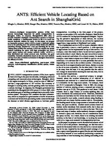
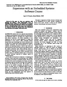
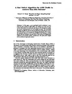
Fig. 1. Testbed results of transmission reliability improvement with multi-AP diversity.
decoded by multiple APs working in the same channel and within its transmission range. By means of this feature, in [2], Miu et al. introduced a Multi-Radio Diversity Combiner (MRDC) to collect the signals received by multiple APs and then jointly decode the frame with a frame combining technique, with which the frame loss due to transmission error can be alleviated. The authors focused on the transmission of a single user, and only transmission error was considered. However, from a network perspective, each user competes for the channel with many neighboring users within its carrier sensing range, and the users outside its carrier sensing range can start new transmissions, which is called spatial reuse. Much research [6][17] has shown that channel contention and spatial reuse, rather than transmission error, are the main factors influencing the performance in throughput. The purpose of our paper is to propose a “Multi-AP” architecture and compare its performance in throughput with the traditional WLANs from a network perspective. Herein, “Multi-AP” means that each user is capable of maintaining multiple associations, and correspondingly the network working in the “MultiAP” mode is called Wireless Multi-AP Network (WMAPN). Because the WMAPN is a MAC-focused solution, several existing physical solutions, such as multi-radio interfaces, multiple-input multiple-output techniques, beamforming antennas, frame combining techniques [2], and the opportunistic channel selection, etc. can be jointly used to further enhance the performance of the networks as in traditional WLANs. In WMAPNs, each user is allowed to associate with multiple APs within its transmission range according to a certain rule, and a sent frame can be acknowledged as long as any one of its associated APs successfully decodes the frame. Due to the independence of different links in collisions and transmission errors, the probability that all associated APs fail to decode the frame is much smaller than that in the single AP case. In our previous work [8], we set up an IEEE 802.11b testbed based on Intel PRO/Wireless 2200 MiniPCI card to study such a multi-AP diversity effect. As shown in Fig.1, the packet loss is reduced greatly when multiple APs are employed. High reliability means less resource waste for retransmissions, and thus the system capacity can be improved. In this paper, we focus on the performance analysis of WMAPNs from a network perspective. Based on the characteristics of WMAPNs, we develop an analytical model, which takes transmission errors, collisions, the capture effect, and the
5031
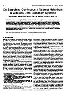
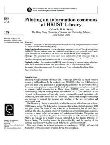
spatial reuse into account, to investigate the relations among throughput, transmission error, user density, traffic load, and position. With the proposed model, we investigate the performance improvement of WMAPNs compared to traditional WLANs, and we illustrate that WMAPNs can alleviate the problems (unfairness due to capture effect, hidden terminal problem, and type II exposed terminal problem) which exist in traditional WLANs. The rest of this paper is organized as follows. In Section II, we describe and analyze the network architecture and the advantages. Then, Section III is devoted to the theoretical formulation over a general physical model. In Section IV, for regular AP distributions we analyze the performance of throughput density. Extensive simulations are implemented in Section V to support the theoretical results. In Section VI, we give a further discussion to the factors which influence the performance in throughput but are not studied theoretically. Related works on our topic are summarized in Section VII. Finally, the conclusions are drawn in Section VIII. II. N ETWORK A RCHITECTURE AND C RITICAL F EATURES In this section, we first describe a typical architecture of WMAPN and explain the function of each type of device involved in the architecture. Then, the critical features of WMAPN compared to the traditional WLAN are illuminated. The proposed scheme is a MAC-solution, and all the existing high-layer (TCP/IP, application layer) devices and services can be implemented upon the WMAPN without any modifications. Therefore, only MAC-layer devices are depicted in this paper. A. Network Architecture Because the IEEE 802.11 standard only provides a limited number of orthogonal channels (3 in 802.11b/g, and 12 in 802.11a), the signal coverage among many neighboring APs working the same channel has to be overlapped 1 in the practical high density deployment [1]. Devices working different channels cannot communicate with each other, and do not interfere with each other as well. A WMAPN consists of several APs working in the same channel, and each user can sense multiple APs within its carrier sensing range and associate with some of them following a certain AP selection algorithm. A service provider can deploy many WMAPNs in the region by tuning them to different orthogonal channels2. Because devices working different orthogonal channels do not interference with each other, and thus we concentrate on a single WMAPN. A typical architecture of WMAPN is shown in Fig.2. There are three types of devices in such an architecture. Besides APs and users, another important device is Access Controller (AC), which is the centralized controller and responsible for managing all APs. Generally, there is only one AC. For a large-scale deployment where a large number of APs working 1 In IEEE 802.11a/b/g, the signal-interference-and-noise (SINR) requirement for successful decoding is so high that the number of channels for frequency multiplexing is more than the number of orthogonal channels available. 2 In this paper, we assume that only orthogonal channels are used in network deployment.
5032
IEEE TRANSACTIONS ON WIRELESS COMMUNICATIONS, VOL. 8, NO. 10, OCTOBER 2009 WLAN switch / AP controller
AP
User
AC
Beacon (AP configure information) Association request
Internet
Association request AP3
Association response
AP1
Update association AP A
Transmit data packets
C
B AP5
AP7
……
AP2
…… (a) Association procedure
AP4
User
Fig. 2.
Association analysis
Association response Update local association list
AP6
Architecture of wireless multi-APs networks.
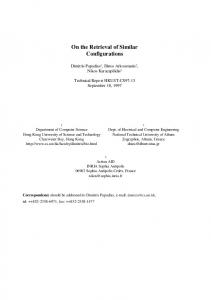
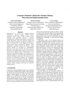
in the same channel, we can divide the whole network into several small WMAPNs so as to alleviate the load of the AC. In the WMAPN, each AP has two suits of physical interfaces: one is wireless radio interface for communicating with users, the other one is wired interface for the connection with the AC. The basic functionalities of each device are described as follows: 1) AC: The main function of the AC is to make AP selection decision and maintain all association information related to the APs it controls. At the association stage, the AC collects the traffic load distribution of the network and the association requests forwarded by the neighboring APs of the considered user, and then makes AP association decision following a certain rule. In addition, the AC is responsible for managing ACKs so as to avoid ACK collisions. When an AP receives a data frame originated from the user associated with it, the AP will create an ACK request frame including the ID of the data frame and forward it to the AC. The AC selects only one of the APs that decode the same data frame to return the ACK with the rule of FCFS (first come first serve), i.e., the AC only replies the first arrival ACK request points to the considered data frame and ignores other ACK requests for the same data frame. 2) AP: Different from that in traditional WLAN, after receiving an association request the AP in WMAPN will not directly decide whether to admit it. The AP forwards the association request to the AC, and then constructs its own association list according to the association response from the AC. At the data delivery stage, when the AP receives a data frame originated from the user associated with it, it will send an ACK request to the AC. If the AP receives the ACK response, it will send the ACK to the user. Basically, the data rate of current wired link (100-1000Mbps) is much larger than wireless link, and the lengths of ACK request and ACK response are very small (on the order of 10s of bytes). Even if many APs transmit simultaneously to AC (in fact it is nearly impossible, because many APs cannot receive the packet at the same time due to different distances to the considered user), the CSMA/CD mechanism employed in wired link can assure that the time of ACK management is smaller than a SIFS (the interval between the data frame and the ACK frame in traditional WLANs), and thus it will not influence the backoff mechanism of the user. 3) User: The functionalities of the user in the WMAPN are the same to those in traditional WLAN: scanning the
AC
AP
Data packet
ACK request
ACK response
ACK response
ACK scheduling
(b) Data delivery procedure Fig. 3.
Working procedures of WMAPNs.
beacon frames, sending association requests, delivering data, and receiving ACK. In this way, the multi-AP architecture is transparent for the user, which is one of the most important features of the WMAPN. The working procedure of WMAPN, which consists of the association procedure and the data delivery procedure, are illustrated in Fig.3. Different from the traditional WLAN, WMAPN needs to employ “ACK request - ACK response” to avoid ACK collisions in the scenario that multiple associated APs received the data frame simultaneously. As described above, the procedure of “ACK request - ACK response” must be finished in a SIFS, which requires the bandwidth of wired link between APs and the AC much be large enough. An alternative solution is to employ No-ACK mechanism defined in IEEE 802.11e to enable APs not to reply ACK after receiving data packets. If a frame loss is detected (by means of frame sequence number), the AC sends a packet-level retransmission request to the user. Then, the user retransmits the packet according to the request. It is a layer 2.5 solution, and it requires some modifications to the driver of users. B. Critical Features Be enabling each user to associate with multiple APs and having a central controller to coordinate them, such a WMAPN has several distinct characteristics that are worth noting. 1) The uplink transmissions (from users to APs) can benefit from multiple backup reception, and they are more reliable than those of traditional WLANs, especially in high density network and high fading channel environment. 2) In downlink, the users can obtain multi-AP diversity as well by selecting one associated AP with less traffic load for downlink transmissions. 3) With the help of multiple associations, the WMAPN has inherent advantage to alleviate the hidden terminal and the type II exposed terminal problems described above. ∙
Hidden terminal As shown in Fig.2, if user B associates with AP 5 only, user C will be a hidden terminal of user
ZHU et al.: LEVERAGING MULTI-AP DIVERSITY FOR TRANSMISSION RESILIENCE IN WIRELESS NETWORKS . . .
B. Alternatively, in the WMAPN, user B can maintain association with both AP 3 and AP 5. Because user B→AP 3 can work well even user C transmit simultaneously, user C will not be the hidden terminal of user B again. ∙ Type II exposed terminal When user B transmits, all APs within its carrier sensing range are blocked. If user C associates with only AP 5, it will be a type II exposed terminal of user B. Alternatively, if user C associate both AP 5 and AP 6, the data frame can be received successfully by AP 6. Then, user C will not be the type II exposed terminal of user B again. 4) With the help of multiple associations, a seamless mobility is feasible. In the WMAPN, when a user roams in the networks it just cuts the association with bad channel gain and still maintains the other associations. At the same time, through periodically scanning, the user can construct new associations to the APs with good channel gains. In this way, the handover is soft, and the user always has some associations available. In this paper, we concentrate on theoretical analysis of the performance improvement brought by Multi-AP architecture. The diversity gain in downlink is traffic load related and hard to be clarified, and thus we consider the uplink only. In addition, the fourth feature is protocol related and will be explored in the future protocol design. III. A G ENERAL A NALYTICAL M ODEL In this section, an analytical model, which considers both collisions and transmission errors, is given to investigate the throughput density. Herein, a transmission is considered to be collided if the received SIR is beyond the threshold required for decoding. Therefore, the proposed model describes the behaviors of users working with capture effect. In the WLAN research, throughput, which is defined as the useful information transmitted in a unit time, is widely adopted to evaluate the performance of the network. However, for a large-scale network with spatial reuse it is very difficult to compute the total throughput directly. WLAN are CSMAbased, and all users within the carrier sensing range of an on-going transmission cannot start new ones, i.e., is allowed only one transmission in the carrier sensing range. Therefore, the total throughput of network can be expressed as 𝑆local × 𝐻, (1) 𝑆total = 𝜂 × 𝐻𝐶 where 𝑆local denotes the local throughput, 𝐻𝐶 denotes the area of carrier sensing range, and 𝐻 is total area of the network. Herein, the local throughput refers to the achievable one-hop throughput when the user transmits. In addition, 𝜂 is a constant representing reuse factor of carrier sensing range. In a chain topology two neighbor’s concurrent transmissions share the carrier sensing region between them, and in a 2-D topology 6 concurrent transmissions share the related carrier sensing range [6][7]. Therefore, we have { 2, in a chain topology 𝜂= (2) 6, in a 2-D topology. For a given network, 𝐻 is fixed, and thus it is reasonable to evaluate the performance. Herein, 𝐹 to employ 𝐹 = 𝜂 𝑆𝐻total 𝑐 is referred to “throughput density”. In the remainder of this
5033
section, we concentrate on the performance analysis of the throughput density in a general model to show the advantage of WMAPNs compared to traditional WLANs. A. The Physical Model Consider a large-scale network. The 𝑗 𝑡ℎ AP is indexed as 𝐴𝑗 (1 ≤ 𝑗 ≤ 𝑀 ) and the 𝑖𝑡ℎ user is indexed as 𝑈𝑖 (1 ≤ 𝑖 ≤ 𝑁 ). To simplify our analysis, only uplink from users to APs is considered. Let 𝑑𝑖,𝑗 denote the distance between 𝑈𝑖 and 𝐴𝑗 . In this paper, it is assumed that the transmit power of all users are the same, and then a typical pathloss model [22] expresses the average signal strength at the receiver as a function of the distance between the transmitter and the receiver, i.e. ( ¯ )𝛼 𝑑 ¯ , (3) 𝑃𝑈𝑖 ,𝐴𝑗 = 𝑃 𝑑𝑖,𝑗 where 𝛼 is the path loss coefficient, ranging from 2 (free space) to 4 (indoor). 𝑃𝑈𝑖 ,𝐴𝑗 denotes the signal strength at 𝐴𝑗 received from 𝑈𝑖 . Finally, 𝑃¯ is the reference receiving signal strength as measured at the reference distance 𝑑¯ (usually 1 meter). Let 𝑃𝐴𝑗 (𝑡) denote the aggregate energy detected by 𝐴𝑗 at time 𝑡, which consists of signal (from intended transmitter), interference (from unexpected transmitter(s)) and noise. Then, we have 𝑃𝐴𝑗 (𝑡) =
𝑁 ∑
𝑃𝑈𝑛 ,𝐴𝑗 𝐼𝑈𝑛 (𝑡) + 𝑃𝑁 ,
(4)
𝑛=1
where 𝑃𝑁 is the power of the ambient noise, and 𝐼𝑈𝑛 (𝑡) is an indicator function, which is given by { 1, if 𝑈𝑛 is transmitting at 𝑡 𝐼𝑈𝑛 (𝑡) = 0, otherwise. To simplify the analysis, we consider the impacts of collisions and transmission errors on transmission failures separately: collisions are determined by interference only; and when no collisions occur transmission failures are dominated by transmission errors which are determined by the noise. When 𝑈𝑖 is transmitting to 𝐴𝑖 at 𝑡, from (3) and (4) the signalto-interference ratio (SIR) observed at 𝐴𝑖 is given by SIR𝑖,𝑗 (𝑡) = ∑𝑁
𝑃𝑈𝑖 ,𝐴𝑗
𝑛=1,𝑛∕=𝑖
𝑃𝑈𝑛 ,𝐴𝑗 𝐼𝑈𝑛 (𝑡)
= ∑𝑁
𝑑−𝛼 𝑖,𝑗
𝑛=1,𝑛∕=𝑖
𝑑−𝛼 𝑛,𝑗 𝐼𝑈𝑛 (𝑡) (5)
From the theory of collisions, 𝐴𝑖 can decode the frame with high probability of success only if during the transmission time the received SIR always exceeds a threshold denoted by 𝛿. Then, from (5), we have 𝑁 ∑
−𝛼 𝑑−𝛼 𝑛,𝑗 𝐼𝑈𝑛 (𝑡) ≤ 𝐷𝑖,𝑗 ,
if ∀𝑡 ∈ [𝑡0 , 𝑡0 + 𝑇 ], (6)
𝑛=1,𝑛∕=𝑖
where 𝐷𝑖,𝑗 = 𝛿 1/𝛼 𝑑𝑖,𝑗 is generally referred to interference radius, 𝑡0 is the start transmission point of 𝑈𝑖 , and 𝑇 is the transmission time of a data frame. Herein, we definition of interference radius is based on the assumption that the nearest interfering source dominates the aggregated interference. In this paper, a conservative carrier sensing is employed to make sure the carrier sensing range can cover the interfering
.
5034
IEEE TRANSACTIONS ON WIRELESS COMMUNICATIONS, VOL. 8, NO. 10, OCTOBER 2009 0.35
0.25
FER
0.20
B. Throughput Density
Data frame with C2=1 ACK frame with C2=1 Data frame with C2=0.9 ACK frame with C2=0.9
0.30
C0 = 0.00005, C1 = 0.0625
0.15 0.10 0.05 0.00 0.0
0.2
0.4
0.6
0.8
1.0
Distance of transmitter-receiver (di,j)
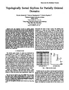
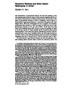
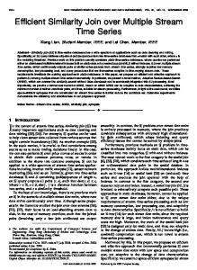
Fig. 4.
𝑆𝑙𝑜𝑐𝑎𝑙,𝑖 =
FER versus the distance of transmitter-receiver.
range of the worst link, and then the effect of the second nearest interfering source can be ignored. Correspondingly, the collision is also defined as that there are concurrent transmissions occur in the interference range, i.e., ∃ 𝑡 ∈ [𝑡0 , 𝑡0 +𝑇 ], 𝑈𝑛 ∈ {𝑈𝑘 ∣𝑘 ∕= 𝑖, 𝑑𝑘,𝑗 < 𝐷𝑗 }
𝐼𝑈𝑛 (𝑡) = 1. (7)
When no collisions occur, i.e., all sources within the interfering range keep silent during the considered transmission, the noise dominates the reception. Under this condition, the signal-to-noise ratio (SNR) is given by: ) ( ¯ 𝑖,𝑗 𝛼 𝑃¯ 𝑑/𝑑 𝑃¯ 𝑑¯𝛼 −𝛼 = 𝑑 . (8) SNR𝑖,𝑗 = 𝑃𝑁 𝑃𝑁 𝑖,𝑗 From [22], the Bit Error Rate (BER) is determined by the SNR, which is proportional to 𝑑−𝛼 𝑖,𝑗 as shown in (8). Then, we model the BER as −𝛼
BER(𝑑𝑖,𝑗 ) = 𝐶0 𝑒−𝐶1 𝑑𝑖,𝑗 ,
For a considered transmission originated by 𝑈𝑖 , the probability of being decoded successfully is denoted by 𝑃𝑠,𝑖 , the probability that the transmission fails due to collisions is denoted by 𝑃collision,𝑖 , and the probability that the transmission fails due to transmission error is denoted by 𝑃error,𝑖 . We have 𝑃𝑠,𝑖 + 𝑃collision,𝑖 + 𝑃error,𝑖 = 1. From [17], the probability that more than two users collide together is very small, and thus we assume that the probability that more than two users collide is zero. When two users collide, the wasted time should be divided by two while calculating the local throughput obtained by each user. In this way, the local throughput derived by 𝑈𝑖 is given by3
(9)
where 𝐶0 and 𝐶1 are both constant, and the values depend on the employed modulation and demodulation techniques. In this way, for any given frame size 𝑙, the FER is given by [ ] −𝛼 𝐶2 𝑙 , (10) FER(𝑙, 𝑑𝑖,𝑗 ) = 1 − 1 − 𝐶0 𝑒−𝐶1 𝑑𝑖,𝑗 where 𝐶2 ∈ (0, 1] is constant and is used to describe the effect of channel coding. Practically, 𝐶2 = 1 when no channel coding is employed. {𝐶0 , 𝐶1 , 𝐶2 } are dependent of wireless environment and the employed physical techniques, which include transmission power, transmission distance, channel coding, modulation and demodulation. In particular, {𝐶0 , 𝐶1 } varies with the transmission distance. With typical values of data frame size (8192 bits) and ACK frame size (192 bits), the FERs of data frame and ACK frame modelled with (10) are plotted in Fig.4. Herein, the distance has been normalized by the transmission radius, and the values of {𝐶0 , 𝐶1 , 𝐶2 } are set to approach to the experimental results shown in [16]. Because the size of ACK frame is much smaller than that of data frame, compared to that of data frame its FER can be neglected.
𝑃𝑠,𝑖 E[𝑃 ] , (11) 𝑃𝑠,𝑖 E[𝑇𝑠 ] + 𝑃collision,𝑖 E[𝑇𝑐 ]/2 + 𝑃error,𝑖 E[𝑇𝑐 ]
where E[𝑃 ] denotes the average frame payload size, and E[𝑇𝑠 ] and E[𝑇𝑐 ] denote the average time that the channel captured by a successful transmission and a collided transmission, respectively. In the remainder of this subsection, we will investigate and compare the achievable throughput density of the user working in the traditional WLANs and that working in WMAPNs. 1) Throughput density in traditional WLANs: Let 𝐸𝑖,𝑗 denote the event that no collisions occur when 𝑈𝑖 sends a data ¯𝑖,𝑗 denotes the event that a frame to 𝐴𝑗 . Correspondingly, 𝐸 collision occurs. In traditional WLANs each user associates with only one AP, usually the nearest one, and thus the probability that a transmission originated by 𝑈𝑖 fails due to a collision is given by ¯𝑖,𝑚𝑗 ) = 1 − 𝑃 (𝐸𝑖,𝑚𝑗 ), 𝑃collision,𝑖 = 𝑃 (𝐸
(12)
where 𝑑𝑖,𝑚𝑗 ≤ 𝑑𝑖,𝑗 for 1 ≤ 𝑗 ≤ 𝑀 . Correspondingly, the probability that the transmission fails due to transmission error is given by 𝑃error,𝑖 is given by 𝑃error,𝑖 = (1−𝑃collision,𝑖 )FER(𝑙, 𝑑𝑖,𝑗 ) = 𝑃 (𝐸𝑖,𝑚𝑗 )FER(𝑙, 𝑑𝑖,𝑗 ). (13) Calculating the successful probability with 𝑃𝑠,𝑖 = 1 − 𝑃collision,𝑖 − 𝑃error,𝑖 and substituting them into (11), we can derive the local throughput directly. Then, the throughput . density can be computed with 𝐹 = 𝜂 𝑆𝐻local 𝐶 2) Throughput density in WMAPNs: Alternatively, in WMAPNs each user is capable of maintaining multiple associations, and the data frame is considered to be received successfully as long as any one of the associated APs decodes the frame. Let Θ𝑖 = {𝜃1 , 𝜃2 , ...𝜃𝑚 } denote the set of APs maintaining associations with 𝑈𝑖 . Without loss of generality, we assume 𝑑𝑖,𝜃1 ≤ 𝑑𝑖,𝜃2 ≤ ... ≤ 𝑑𝑖,𝜃𝑚 . Then, the probability that a transmission originated by 𝑈𝑖 fails due to collisions is given by 𝑃collision∗,𝑖 = 1 − 𝑃 (
∪
𝐸𝑖,𝜃𝑗 ),
(14)
𝜃𝑗 ∈Θ𝑖 3 In practical system, the time for a collision is in order of millisecond, but a slot time is just several microsecond. Therefore, the impact of the time for idle on the throughput is neglected.
ZHU et al.: LEVERAGING MULTI-AP DIVERSITY FOR TRANSMISSION RESILIENCE IN WIRELESS NETWORKS . . .
5035
and the successful probability is given by ∑ ∩ ∏ ∩ ¯𝑖,𝜃 )×(1− 𝑃( 𝐸𝑖,𝜃𝑗 FER(𝑙, 𝑑𝑖,𝜃𝑗 )). 𝑃𝑠∗,𝑖 = 𝐸 𝑘 Φ⊂Θ𝑖
𝜃𝑗 ∈Φ
¯ 𝜃𝑘 ∈Φ
𝜃𝑗 ∈Φ
¯ = Θ𝑖 − Φ. where Φ Then, the probability that the transmission fails due to transmission error can be computed by 𝑃error*,i = 1 − 𝑃collision∗,𝑖 − 𝑃𝑠∗,𝑖 . Substituting the expressions above into (11), we can derive the local throughput in WMAPNs. From the analysis above, the successful probability 𝑃𝑠∗,𝑖 in WMAPNs is always no smaller than that in the traditional WLANs as long as 𝑚𝑗 ∈ Θ𝑖 , 𝑖.𝑒. 𝑚𝑗 = 𝜃1 is guaranteed. However, associating more APs does not always results in the enhancement of the throughput density, because that: if ¯𝑖,𝜃𝑚 always results in 𝐸 ¯𝑖,𝜃𝑛 , i.e. all ∃𝜃𝑚 , 𝜃𝑛 ∈ Θ𝑖 satisfies 𝐸 users that locate in the interfering range of 𝑈𝑖 -𝐴𝜃𝑚 are also covered by the interfering range of 𝑈𝑖 -𝐴𝜃𝑛 , then associating 𝐴𝜃𝑛 does not bring the improvement of the throughput density. In addition, it is observed that the performance improvement depends on the position between each user and the associated APs, the traffic load, and the frame error model(10). The analysis above shows that the performance of WMAPN is dependent of many factors, such as the position relationship of users and APs, the number of APs associated with the user, and the channel conditions. To quantify the performance gain of WMAPN, in the next section we take two regular topologies as example to compute the performance improvement level compared to the traditional WLAN. IV. T HROUGHPUT D ENSITY A NALYSIS OVER R EGULAR T OPOLOGY To quantify the performance improvement degree, in this section we consider two typical regular topologies: a chain topology and a grid topology, and give the numerical analysis for those two topologies. Note that the MAC mechanism we discussed in this paper is CSMA 𝑝-persistent. In [18], the authors illuminated that the 𝑝-persistent closely approximates the standard protocol with the same average backoff window size. Therefore, it is reasonable to infer the behavior of the standard protocol from the analytical results based on the 𝑝persistent protocol. To simplify the computation, the payload size of data frame is fixed. A. In a Chain Topology First, we investigate a chain topology with fixed AP interval as shown in Fig.5. The distance between neighbor APs is fixed as 𝐿. All users are randomly located in a line with uniform probability independent of other users, the user density is 𝜆 (users / 𝑚2 ). Let 𝑃𝑛 (𝛾) denote the probability that there are 𝑛 users in a given length 𝛾, then we have (𝜆𝛾)𝑛 −𝜆𝛾 𝑒 . (16) 𝑛! For the traditional WLANs where each user only associates with the nearest AP, the carrier sensing threshold should be set to satisfy the case that the user locates in the middle of two 𝑃𝑛 (𝛾) =
R2
R1
(15)
IV AP3
II
0 AP1
I
User
L
x
AP2
III
V AP4
C
Fig. 5.
Network sketch of the chain topology.
neighbor APs, i.e. the distance to the nearest AP is 𝐿/2. In traditional WLANs, a conservative carrier sensing threshold is set to eliminate the hidden terminal problems. Under this condition, the optimal carrier sensing radius [6] is given by 𝐶 = 𝐿2 (1 + 𝛿 1/𝛼 ). To guarantee the fairness of comparison, the carrier sensing radius in WMAPNs is also set to 𝐶. As shown in Fig.5, we consider a user which is 𝑥 (𝑥 ≤ 𝐿/2) away from the nearest AP. From the figure, the distances to two 1𝑠𝑡 tier neighbor APs (AP 1 and AP 2) are respectively 𝑥 and 𝐿 − 𝑥 (the related interfering radiuses are denoted by 𝑅1 and 𝑅2 , respectively.), and the distances to two 2𝑛𝑑 tier neighbor APs (AP 3 and AP 4) are respectively 𝐿 + 𝑥 and 2𝐿 − 𝑥. Because in practical system 𝛿 1/𝛼 is larger than 1 (typical value is 2), 𝛿 1/𝛼 (𝐿 + 𝑥) > 𝐿 + 𝑥𝛿 1/𝛼 and 𝛿 1/𝛼 (2𝐿 − 𝑥) > 𝐿 + (𝐿 − 𝑥)𝛿 1/𝛼 always hold. In this way, the interfering ranges of AP 3 and AP 4 always cover that of AP 1 and AP 2, respectively. From the discussion in the previous section, associating AP 3 and AP 4 will not bring any gain, and thus we only consider the situation associating with AP 1 and AP 2. Then, the related area is divided into 5 regions: 1) Region I: the overlaid interfering region of AP 1 and AP 2. The simultaneous transmissions in this region can disturb the reception in both AP 1 and AP 2. 2) Region II (III): the interfering region of AP 1 (AP 2) except the overlaid. The simultaneous transmissions in this region just disturb the reception in AP 1 (AP 2). 3) Region IV: the carrier sensing region except the interfering region, which is named exposed region. The transmissions in this region will not disturb the reception in AP 1 and AP 2, but the users in this region cannot start new transmissions during the considered user being transmitting. The users in this region are generally called exposed terminals. 4) Region V: hidden region. The simultaneous transmission in this region can disturb the reception of AP 2, and the users in this region is capable of starting new transmissions to disturb AP 2 while the considered user is transmitting due to it out of the carrier sensing range. For the chain model, the region is measured with length. With a simple calculation, we obtain the length of each region as follows: 𝑅𝐼 (𝑥) = 𝐿(𝛿 1/𝛼 − 1);
𝑅𝐼𝐼𝐼 (𝑥) = 𝐶 − 𝑥(𝛿 1/𝛼 − 1);
𝑅𝐼𝐼 (𝑥) = (2𝑥−𝐿)𝛿 1/𝛼 +𝐿; 𝑅𝐼𝑉 (𝑥) = 𝑅𝑉 (𝑥) = 𝐶−𝑥(𝛿 1/𝛼 +1).
5036
IEEE TRANSACTIONS ON WIRELESS COMMUNICATIONS, VOL. 8, NO. 10, OCTOBER 2009
TABLE I PARAMETERS OF WLAN S .
From the analysis, the ergodic probability of 𝐸1,1 is given by ∏ lim 𝑃 (𝐼𝑈𝑛 (𝑡) = 0) 𝑃 (𝐸1,1 ) = =
users in Region I&II ∞ ∑
𝑡→∞
𝑃𝑛 [𝑅𝐼 (𝑥) + 𝑅𝐼𝐼 (𝑥)](1 − 𝑝)𝑛
(17)
𝑛=0
Parameter
value
Physical header(bytes) MAC header (bytes) ACK (bytes)
24 34 14
SIFS time (us) Slot time (us) DIFS time (us)
10 20 50
= 𝑒−2𝑝𝜆[𝑅𝐼 (𝑥)+𝑅𝐼𝐼 (𝑥)] .
Substituting them into (11), we can derive the local throughput, and then the throughput density can be obtained with 𝜂 𝑆𝑙𝑜𝑐𝑎𝑙 (𝜂 = 2). 2𝐶 Alternatively, for WMAPNs, the probability that the transmission fails due to collisions is given by 𝑃collision∗,1 (𝑥) = 1 − 𝑃 (𝐸1,1 ∪ 𝐸1,2 ) ¯1,1 ∩ 𝐸1,2 ) = 1 − 𝑃 (𝐸1,1 ) − 𝑃 (𝐸 ⎧ 𝐿(1 − 𝛿 −1/𝛼 ) 1−𝑒−𝑝𝜆(𝑅𝐼 (𝑥)+𝑅𝐼𝐼 (𝑥)) , 𝑥≤ 2 ) ( ⎨ 1−𝑒−𝑝𝜆𝑅𝐼 (𝑥) [1 − 1 − 𝑒−𝑝𝜆𝑅𝐼𝐼 (𝑥) ( ) = −𝑝𝜆𝑅𝐼𝐼𝐼 (𝑥) 1 − 𝑒 × max{0, 1 − 𝑅 (𝑥)/𝐶} ], 𝑉 𝐿(1 − 𝛿 −1/𝛼 ) 𝐿 ⎩