Efficient Airport Snow Shoveling by Applying Autonomous. Multi-Vehicle ..... snow shoveling simulation running the first part of the Frank- furt International Airport ...
This is an author submitted version of the paper. For final version, please contact authors at
http://mrs.felk.cvut.cz
Efficient Airport Snow Shoveling by Applying Autonomous Multi-Vehicle Formations Martin Saska, Martin Hess and Klaus Schilling Abstract— An efficient snow cleaning system is essential for optimal airport traffic during the winter term. In this paper an autonomous approach based on formation driving of cooperative mobile vehicles is described. The method is composed of two independent elements. The route scheduling part designs a time optimal plan for all robots and the formation driving method on the other hand guides the ploughs in an appropriate way during the shoveling. The bridge connecting both modules is a path generator, which creates a feasible trajectory for the reference points of the formations. Optimality for the covering task is achieved by splitting and reuniting the robot groups depending on the varying size of the runways. The robustness of the algorithm is increased by the ability to adjust the formations shape reactively on obstacle detection. The proposed method was verified by simulations in the environment of the International Frankfurt Airport as well as by hardware experiments in a test field.
I. INTRODUCTION Snowy weather has a huge impact on the traffic throughput of big international airports, whose departure and arrival schedules are highly optimized. Technically mature sensors, communication and navigation systems allow to launch and land even during snowfall but the condition of the runways is a major limiting factor. Today the tracks of an airport usually are freed from snow by utilizing a fleet of human driven snowploughs. An increase of efficiency can be achieved by setting up a periodical autonomous system based on groups of car-like mobile robots shoveling in formation. In the approach presented in this paper the airport operations are maintained by switching the runways between active and shoveling mode. Due to the formation driving, all roads are cleaned always completely, which eases the handling of emergency landings and other unexpected rescue operations. In the presented algorithm minimal cleaning time in each zone of the airport and complete cleaning of the whole airport during one loop is guaranteed. The short execution time is accomplished by splitting formations for shoveling smaller roads and by reuniting them to a significant number for the main runways. The developed method has been intensively tested in various simulations as well as in laboratory hardware experiments. As a testing scenario for the proposed task scheduling algorithm Frankfurt international airport was chosen, which is one of the largest airports in Europe. Due to the decomposition of the optimization problem to various subproblems focusing on each runway and its close environment the approach can be applied to other airports as well.
The snow shoveling task addressed in this paper is related to the field of cooperative sweeping strategies, whose aim is to find and execute a motion for the robots in order to cover a predefined area by their effecters, which are in our case the snowploughs’ shovels. Often it is desired to coordinate the vehicles in a way that time optimality is achieved. Kurabayashi et al. addressed the problem of cooperative sweeping by generating a path for a single robot which is then segmented and distributed among the vehicles [8], [7]. A decentralized approach using an online negotiation mechanism to resolve the task sharing was proposed in [11]. Luo et al. developed a real-time method based on biologically inspired neural networks where each robot treats the other robots as moving obstacles [9], [10]. Projecting the problem of cooperative sweeping onto the airfield snow shoveling task generates some problems that have not yet been addressed. The approach described in the following considers the nonholonomic kinematics of usual snowploughs as well as position and orientation of the ploughs’ shovels. Also the working space is more structured due to the airfield environment and the robots are more closely connected with each other during the cleaning task than it is the case in the methods mentioned above. The following section describes how the optimal schedule for the snowplough-robots is derived. In Section III the path generation and the motion coordination of the vehicle formations are introduced. Finally the results of the hardware experiments are presented followed by concluding remarks and directions of future work. II. ROUTE S CHEDULING
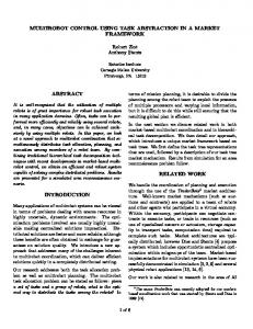
In this section a route scheduling approach for snow shoveling of an airport by autonomous mobile robots is introduced. The core of the algorithm is a graph describing all roads which need to be cleaned up by edges and whose nodes represent the centers of all crossings. In the graph each runway and each service road should be replaced by an appropriate number of edges depending on the amount of vehicles needed for the shoveling. A simple example of such a graph is depicted in “Fig. 1”. Due to simplification all edges inside the square field are of the same length, while the edges along the borders are two times as long. The final schedules, which are an output of the algorithm, should cover all edges at least one time. The result moreover should be optimal with respect to total time needed and it should fulfill the constraint that the robots do not take the edge from where Authors are with Julius-Maximilians University of Wuerzburg, Germany {saska,m.hess,schi}@informatik.uni-wuerzburg.de they came from.
111 511
Fig. 1.
Shoveling scenario containing 5 nodes.
The simplest way for finding the optimal solution is achieved by using the well known ”breadth first” algorithm. With this method a tree of states is usually explored completely. In our case a state is described not only by the actual positions of all robots, but also by the history of their movements. “Fig. 2” shows a part of the tree found for the simple scenario from “Fig. 1”. The tree prepared for three robots is partly reduced due to limited space in the figure. The total number of leafs in the tree is greater than 140000. In the initial state of planning (first level in the tree) one robot just arrived at node 1 while the other robots are coming sequentially. In the next step the second robot is prepared in node 1, the third robot arrives soon and the first robot is already heading towards one of the adjacent nodes. The nodes in the tree (length of the vectors agrees with number of robots) symbolize all possible actual positions of the robots, whereas the history of their movement can be extracted from the path between the appropriate node and the root. The numbers symbolize nodes in the graph (of the airport), to which the appropriate robot is heading. The nodes marked by underline are already reached by the robot and in the next step the tree will be expanded in this place. At the beginning the robots arrive in short intervals, so a rendezvous in the same crossing during their job is avoided and therefore just one number is underlined in each state. In the middle column an optimal schedule for three robots covering the whole map is depicted. Optimality of the final solution can be guaranteed if all states with shorter total shoveling time are expanded. It is easy to see that a complete schedule cannot be shorter than total number of cleaned edges N , because each road needs to be cleaned up at least one time. Therefore a tree with a depth greater equal than N has to be created. PN A lower bound for the number of expanded states is l=0 bl , where b is the minimal branching factor. in our simple example P10 While l the bound is equal to 2 , in the graph of Frankfurt l=0 airport that was used as testing scenario this value is equal P761 l to l=0 2 , which renders it unsolvable for the described method. Fortunately not all of the states are feasible. Usually each airport has several parallel runways with appropriate service roads. In order to prevent collisions between snowploughs
211
411
541 551 521 441 451 421 241
251 221
554 555 552 454 452 455 254
255 252
455 355 255 442 432 422 245
235 225
345 335 325 332 532
234
233 232
344 333 322 522 542 334 534
532 332
444 244 523 525 545 543
542 522
214 234
523 521
345 245 145
231 233 244 243 241 123
323 423
133 533 143 343 341 141
423 223
153 123 113 153 353 313 151 112 114 354 352 152 154 Fig. 2.
111 112 114
Reduced tree with an optimal schedule in the middle column.
and the airport traffic, such parts should be shoveled separately. During the cleaning phase airport traffic is not allowed to enter the area and conversely the other parts of the airport are forbidden for the ploughs at this time. Frankfurt airport is usually using two parallel runways labeled A and B. For the scheduling algorithm we divided all roads to the three nonoverlapping sets A, B and AB “Fig. 3”. The edges of set A (resp. B) need to be cleaned up completely while runway A (resp. B) is in shoveling mode, because these roads are used by airplanes, when the appropriate runway is in active mode. Edges of set AB can be cleaned up with set A or B, but together at least with one of them. These auxiliary roads are only used by the ground crews, which are able to avoid the snowploughs. Therefore they do not need to be closed for the robots. Another indispensable simplification is given due to safety regulations, which require shoveling each road at once. The reason is that partly cleaned paths with snow hills remaining on the surface could be dangerous in emergency situations. For rescue and fire fighting vehicles and for planes making a forced landing, roads with a constant layer of snow are safer than those with a cluttered surface. The mentioned simplification of the searched space results from the specific character of the airport. The service roads are almost two times narrower than the main runways. Due to this we can expect that the optimal solution will be to firstly clean the runway by a big formation and to divide it to two equal parts afterwards in order to clean up the remaining roads. Hence in the final solution there is no time wasted for robots waiting for others to form up. The reduced lower bound of the number of statesP needed 40 l for scheduling both parts will be approximately l=0 2 which is still unsatisfactory. To improve the algorithm the
selection rule that determines the state that will be expanded in the next step was changed. In the ”breadth first” algorithm usually the firstly found state that is still unexpanded is chosen. But if instead the unexpanded state with the lowest waste time (time lost by using a path that does not need to be cleaned up or by waiting for the second formation at the end of the plan) will be expanded, the most promising solutions are favored. Because all states with lower waste time than in the firstly found solution are already evaluated, the result has to be time optimal. A pseudo code of the algorithm can be found in Algorithm 1. The total number of states which were evaluated during scheduling of part A is equal to 61520. The optimal solution that is depicted in “Fig. 4” could be found during 32 minutes using a Pentium 4 CPU 3.2GHz, 512MB of RAM. The cleaning loop for the complete airport of Frankfurt can be summarized in the following 6 steps: 1) All robots clean the runway of area A in a big formation. The schedule is a sequence of the edges from node 2 to node 31. 2) Two smaller formations clean the remaining edges of area A, where the edges of AB can be also used. The schedule of this step depicted in the “Fig. 4” was found by the algorithm described above. 3) Both formations move to node 19. The shortest path is found by the Dijkstra algorithm [3]. 4) The reunited formation cleans the runway of area B from node 19 to node 79. 5) The newly divided formations clean all edges of B + AB that were not cleaned up in steps 2)-4) The already cleaned edges of B + AB can be used during this step too. 6) Both formations move to node 2 and the sequence is restarted with step 1). Algorithm 1: Pseudo code of the scheduling algorithm. SOLUTIONS ←− ∅ UNEXPANDED ←− initialState expandingState ←− ShortestTime(UNEXPANDED) UNEXPANDED ←− UNEXPANDED − expandingState while UNEXPANDED 6= ∅ && UncleanedRoads(expandingState) 6= ∅ do node ←− StaticNode(expandingState) NEWNODES ←− Successors(node) foreach newNode of NEWNODES do newState ←− AdvancedState (newNode,expandingState) UNEXPANDED ←− UNEXPANDED + newState if UncleanedRoads(newState) = 0 then SOLUTIONS ←− SOLUTIONS + newState
expandingState ←− ShortestTime(UNEXPANDED) UNEXPANDED ←− UNEXPANDED − expandingState
if UNEXPANDED = ∅ then return NoSolution else return ShortestTime(SOLUTIONS)
Fig. 3. 3 sets.
Map of Frankfurt Airport with roads and runways partitioned into
ShortestTime returns the state with the lowest lost time which is caused by waiting or moving along already cleaned roads.
31
30
28
31 29
0
500
26 23 22 21
26 22 23
100
12 13
12
27
200
14 52 50 8
10
600
9 10
25
20
25
20 19 18 17
300 11
400
9 8 49
7
700
800
6
25 5 6
3 1 2 4 3
25 5
86
900
Time [sec]
Fig. 4. Time schedule for cleaning the service roads in area A. The sequences for two formations show order and time in which each node should be visited.
UncleanedRoads creates a list of uncleaned roads in the current state. StaticNode returns the node (of the graph) where a formation recently finished its task. Successors returns all feasible nodes that can be reached from the actual node in one step. AdvancedState returns the new state which results from moving the formation from StaticNode towards the specified node. III. M OTION C OORDINATION A. Path Generation The derived schedule provides the desired order for visiting all roads to clean on the airfield. To be able to move the snowploughs towards these points of interest, a path needs to be created that connects them in the correct order. The path has to be feasible for the formation of vehicles, which should track it during the shoveling task. Also it should be placed in a way that the ploughs create a snow-free track which is as wide as possible. The first state of the path is achieved by connecting the points of interest by line segments in the correct order. A simple example is shown in “Fig. 5”, where the solid path of straight line segments refers to the shortest route connecting the points P1 with P2 and P2 with P3 . Since this path cannot be followed by a snowplough which is usually a vehicle with car-like kinematics the sharp edges need to be replaced by curves. The solid curve in the figure characterizes the circular arc (a curve with constant curvature) which connects the intersection points of the dashed lines u1 , v1 with the solid thick lines. The dashed lines intersect with each other in the arc’s center S1 which lies on the bisecting line of the sharp edge at P2 . The intersection with the thick solid segments is chosen at equal distance from P2 , which has to be great enough to guarantee a radius greater equal the minimum turn radius of the vehicles. Intuitively the solid curve path seems to be traceable by a car-like vehicle. However if the car is moving, in the connection points its steering angle would need to change in an instant of time from 0 to a certain value or vice versa. One possible solution would be to stop
Fig. 5.
Different paths for connecting the points P1 , P2 and P3 .
the plough in the connection points and adjust the steering angle at zero speed. It is comprehensible that these rests would make the approach very inefficient. The more elegant solution is to replace the sharp edges of the path in first state by segments with continuous curvature (CC) [4]. In “Fig. 5” such CC-turns are depicted by the dashed curves. It consists of a clothoid arc reaching from the initial point of the turn (intersection with line v1 ) to the intersection with line v2 , which is also chosen with respect to traceability. Its curvature varies from 0 to the curvature k of the second segment which is a circular arc. The third and final segment is a clothoid arc of inverted sharpness to the first one which varies from k to 0. Due to the continuous curvature profile of the CC-turn the whole path can be followed without stopping. However there are some limitations which need to be considered for the path planning but these will be discussed later in this section. The final desired path with CC-turns can be parameterized by its arc length s resulting in two functions xd (s) and yd (s). To transform the path into a reference trajectory for the snowplough formations, a suitable speed profile vd (s) is assigned along the path. B. Formation Driving Methods for formation driving are often based on maintaining a certain distance to a moving reference point which could be a leading vehicle, the barycenter of the group or even a predefined point. Since car-like vehicles are nonholonomic, i.e. they cannot accelerate in an arbitrary direction neither they can turn on the spot, this is not very applicable in the Cartesian space. To achieve coordinated driving anyway we rely on the idea to maintain the distance to the reference point in curvilinear coordinates [6]. “Fig. 6” shows three
(a)
(b)
Fig. 7. Barycenter tracking (a) vs. shovel center tracking (b). The dots denote the path performed by the cars barycenter while the solid lines denote the shovels position. Fig. 6.
Snowplough formation is maintained in curvilinear coordinates.
snowploughs in formation where C is the reference point and pi and qi denote horizontal and vertical distance from the i-th vehicle to C respectively. pi as well as the traveled distances of the reference point sc and the vehicles si are always measured along the reference path and therefore si = sc + pi .
(1)
It can be seen that the Euclidean distances between the ploughs slightly vary depending on the momentary curvature of the reference trajectory. This deformation effect is upper bounded and therefore unproblematic if the initial values for pi are chosen such that the distance between the vehicles is big enough. xd (si ) and yd (si ) provide the position of the reference point at the traveled distance of vehicle i. Then, with respect to qi the desired position for the i-th snowplough can be computed as x(si , qi ) = x(si ) − qi sin(θi ) y(si , qi ) = y(si ) + qi cos(θi ),
(2)
where θi is equal to the orientation of vehicle i measured against the x-axis. Next to the inner dashed path in “Fig. 5” another dashed curve shows the computed path for a vehicle with qi < 0 . The quadratic marks on both curves are placed on equal traveled distances along the reference path. It can be seen, that a vehicle on the outer path has to move faster in order to keep up with one on the dotted reference path and its steering angle has to be less. To follow the desired trajectories a trajectory tracking controller developed for car-like robots was implemented on each snowplough. In [2] a controller is described, that utilizes exact feedback linearization on the kinematic equations for the barycenter of the robot located at the center of its rear axle. The controller was tested within various hardware experiments which proved its applicability except in sharp turns (see “Fig. 7(a)”). The bigger the distance between shovel and barycenter of the plough, the more the cleaned part deviates from the desired path. To get around this problem we choose the shovels mount point as the position which should track the desired trajectory. The resulting controller handles sharp turns in a much more efficient way as it can be seen in “Fig. 7(b)”. For these controllers to work properly an accurate positioning system is needed, because if the snowploughs controller does not know the vehicles
Fig. 9. A formation of 4 snowploughs overcomes a bottleneck along the road by appropriately adapting their q-variables.
own coordinates, it is for sure not able to correct the error between real and desired position. But since the site to clean is not changing a positioning system (e.g. DGPS) can be installed in situ. For the snow removal the formation should be arranged in such a way that the snow is transported to the side of the roads. “Fig. 8” shows two snapshots of the implemented snow shoveling simulation running the first part of the Frankfurt International Airport schedule created earlier. While cleaning the main runway the autonomous vehicles form a wedge. At the end of the runway the formation splits up into two smaller groups in order to clean the smaller auxiliary roads separately. Snowploughs reaching this point switch into another group by immediately changing their q-variable to an appropriate value and follow the new reference trajectory respectively. Referring to the nature of car-like vehicles the shovel does not cover the path with its complete length when turning, i.e. the orthogonal projection of the shovel to the tangent of the path is slightly changing. Therefore the vehicles are arranged in such a way that their shovels overlap a little even during maximal turning. This also leaves some tolerance for temporary displacements due to uncertainties in the position determination. In some cases it is useful to alter the arrangement of a formation while its vehicles are in motion. This can be e.g. in order to adapt to a changing environment like a road getting narrower, to avoid an obstacle, which can be a parking transporter or to adjust the formation structure after switching to a new group. Such deformations are achieved by appropriate and continuous alteration of the p- and qvariables [1]. An example of such a maneuver can be seen in “Fig. 9”, where a formation consisting of 4 snowploughs overcomes a bottleneck along the road. As it was mentioned before there exist some limitations which need to be considered when designing new paths
Fig. 8.
Snapshots from the snow shoveling simulation running the first part of the Frankfurt International Airport scenario (unit in meters).
for formations of car-like robots. Since speed and curvature of turns are usually upper bounded the maximum values for speed and steering of each car have an effect on the maximum values for speed vd and curvature kd of the reference trajectory. Let us assume the case of a static homogeneous formation, i.e. the arrangement of the vehicles given by pi and qi remains constant for all i and all vehicles have the same properties. On a straight path segment vd is upper bounded only by the maximum speed of the vehicles. But during a turn one has to take care that the inmost car of the formation, which is the one with the lowest turning radius in this curve, is able to reach its desired steering angle. In a similar fashion it should be considered that the outmost car has to drive with the highest speed of the group. Another upper bound for the speed during turns might be given depending on how fast the inmost car can change its steering angle during the clothoid segments. With respect to the arrangement of the formation and the characteristics of the curve the lower speed bound needs to be fulfilled. IV. H ARDWARE E XPERIMENT This section describes the snow shoveling hardware experiments that were carried out within the MERLIN-Testbed of the University of Wuerzburg [12]. The aim of the hardware experiments was to verify the results of the simulations in a real environment, because within the simulations the dynamic behaviors are based only on estimated models. The MERLIN-Testbed consists of multiple homogeneous carlike robots which are equipped with various sensors like wheel encoders, gyroscope and ultrasonic range finders. Each
vehicle also contains a wireless communication device to enable inter-robot data-exchange. For the experiments the snow was made of small pieces of polystyrene and the shovels are simply straight bars, which were mounted transversely to the bumper of the mobile robots (details are described in [5]). The scenario includes most important parts of the described approach referring to formation coordination and control. “Fig. 10” depicts three snapshots of one shoveling cycle. The two snowploughs start to remove the snow from the main runway in a formation. After shoveling the first turn cooperatively the formation is split to clean the smaller roads separately. Before the snowploughs reunite the vehicle on the center road has to wait for the other one to pass by. Otherwise the robot coming from the outer slope would leave an amount of snow in the turnoff. Actually the other robot lost some snow particles in the intersection of the roads. But this results from the simple design of the shovels and would not happen when utilizing modern snowploughs. Once the robots are reunited, they split vertically during the next turn in order to proceed to the starting point along the main runway. The position determination of the robots in the experiment relies on dead reckoning which is based on information obtained from wheel encoders and gyroscope. Therefore the position error accumulates with time. Furthermore it is not possible to correct the initial position and orientation error. As it was mentioned before an accurate positioning system should be utilized in the real application in order to obtain external feedback for the robots absolute position.
appropriate reallocation of the vehicles to the cleaning groups in real time. VI. ACKNOWLEDGMENTS This work was supported by the Elitenetwork of Bavaria through the program ”Identification, Optimization and Control with Applications in Modern Technologies”. R EFERENCES
Fig. 10.
Snapshots from the snow shoveling hardware experiments.
V. CONCLUSIONS AND FUTURE WORK A. Conclusions In this paper a novel snow shoveling method for airports was presented. The proposed multi-robot system performs the shoveling more efficient than a group of large independent snowploughs. Additionally the systems flexibility and maneuverability allow the utilization of the autonomous shoveling robots for various parts of the airfield. During the task the formations can be split and combined to variously sized formations depending on the width of the roads to clean. Narrow segments of the road and detected obstacles can be avoided by an adjustment of the formation’s shape as well. The introduced algorithm offers optimal and complete shoveling while the airport operations are not tied up completely. B. Future Work In future work we will focus on extending the task scheduling in order to find a global optimal sequence for the complete airport. At the moment we can only verify optimal solutions for each subsection, but there might exist a better distribution for the unclassified paths. Furthermore the robustness of the method against unexpected situations needs to be improved by making the approach more dynamic. The real application requires immediate adjustments of the schedule if a part of the airport gets closed or if a road is blocked by an obstacle. Also the compensation of a failed robot needs to be done by an
[1] T. D. Barfoot and C. M. Clark, “Motion planning for formations of mobile robots,” Robotics and Autonomous Systems, vol. 46, pp. 65–78, February 2004. [2] A. De Luca, G. Oriolo, and C. Samson, “Feedback control of a nonholonomic car-like robot,” in Planning robot motion, J.-P. Laumond, Ed. Springer-Verlag, 1998. [3] E. Dijkstra, “A note on two problems in connexion with graphs,” In Numerische Mathematik, vol. 1, pp. 269–271, 1959. [4] T. Fraichard and A. Scheuer, “From reeds and shepp’s to continuouscurvature paths,” IEEE Transactions on Robotics, vol. 20, no. 6, pp. 1025–35, December 2004. [5] M. Hess, M. Saska, and K. Schilling, “Autonomous multi-vehicle formations for cooperative airfield snow shoveling,” in Proc. of the 3rd European Conference on Mobile Robots (ECMR07), Freiburg, Germany, 2007. [6] ——, “Enhanced motion planning for dynamic formations of nonholonomic mobile robots,” in Proc. of the 6th IFAC Symposium on Intelligent Autonomous Vehicles (IAV2007), September 2007. [7] D. Kurabayashi, J. Ota, T. Arai, S. Ichikawa, S. Koga, H. Asama, and I. Endo, “Cooperative sweeping by multiple mobile robots with relocating portable obstacles,” in Proc. of the Conf. on Intelligent Robots and Systems, Osaka, Japan, 1996, pp. 1472 – 1477. [8] D. Kurabayashi, J. Ota, T. Arai, and E. Yoshida, “Cooperative sweeping by multiple mobile robots,” in Proc. of the Conf. on Robotics and Automation, Minneapolis, Minnesota, 1996. [9] C. Luo and X. Yang, “A real-time cooperative sweeping strategy for multiple cleaning robots,” in Proc. of the Symp. on Intelligent Control, Vancouver, Canada, 2002. [10] C. Luo, X. Yang, and D. Stacey, “Real-time path planning with deadlock avoidance of multiple cleaning robots,” in Proc. of the Conf. on Robotics and Automation, Taipei, Taiwan, 2003. [11] T. Min and H. Yin, “A decentralized approach for cooperative sweeping by multiple,” in Proc. of the Conf. on Intelligent Robots and Systems, Victoria, Canada, 1998. [12] K. Schilling and Q. Meng, “The merlin vehicles for outdoor applications,” in Unmaned Ground Vehicle Technology IV, Proceedings of SPIE, G. R. Gerhart, C. M. Shoemaker, and D. W. Gage, Eds., vol. 4715, 2002, pp. 43–49.