TELKOMNIKA Indonesian Journal of Electrical Engineering Vol. 12, No. 11, November 2014, pp. 7650 ~ 7658 DOI: 10.11591/telkomnika.v12i11.6573
7650
Hysteresis Current Control with Input Filter Design for High Frequency Series Resonant Full Bridge Inverter Debabrata Roy*1, Pradip Kumar Sadhu2, Nitai Pal2
1
Batanagar Institute of Engineering Management & Science, B7-360 / New,Ward No. 30, Putkhali, MaheshtalaKOLKATA - 700141West Bengal, India 2 Electrical Engineering Department, Indian School of Mines (under MHRD, Govt. of India *Corresponding author, e-mail:
[email protected]
Abstract This paper talks about the analysis of a high frequency series resonant inverter for using domestic and industrial induction heating purpose. It is a technique i.e. used for heat conductive materials hard and soft metals. Series Resonant inverters which operate at high frequency preferable for induction heating which normally works in 5-55KHz. High frequency series resonant inverters which is made up of Insulated Gate Bipolar Transistor (IGBT). Power control is obtained by Hysteresis Current Control and filter design is incorporated in the input power supply. Soft switching techniques is performed which minimizes switching losses and proper filter design minimizes harmonic injection in the power supply. Keywords: induction heating, series resonant inverter, hysteresis current control, high frequency, IGBT Copyright © 2014 Institute of Advanced Engineering and Science. All rights reserved.
1. Introduction To heat conductive materials high frequency induction heating is needed. To heat electrically conductive materials high frequency electricity is being used. Vast amount of current is feed to the coil using high frequency electricity. It is known as a work coil. A very forcefully and quickly changing magnetic field in the space within the work coil is generated when current is fed to this coil. The work piece is to be heated. Then within intense alternating magnetic field the heated work piece is kept. A current flow in the conductive work piece is induced by the alternating magnetic field. It is heated. The work coil as well as the work piece can be considered of as an electrical transformer. In this case it is assume that work coil is considered as primary in which electrical energy is feed in the work piece is like a single turn secondary that is short-circuited. This short circuited work piece induces inrush of currents to flow which is called eddy currents. The magnetic field is formed around a coil when the AC current enters the coil. It is calculated according to Ampere’s Law:
H dl
N i f .................................(1)
H A .............................................( 2 ) Faraday’s Law states that the current that is generated on the conductive object has an inverse relationship with the current on the inducting circuit. An eddy current is generated from the current on the surface of the object and it is calculated has follows:
E
d d N .........................(3) dt dt
As a result, the electric energy caused by the induced current and eddy current is converted to heat energy:
P
E2 i 2 R ....................................( 4 ) R
Received August 16, 2014; Revised September 14, 2014; Accepted October 1, 2014
ISSN: 2302-4046
TELKOMNIKA
7651
In induction heater in which resonant tank is installed, made of heating coil and capacitor, high frequency series resonant inverters are used. High Frequency Series resonant inverters are those in which resonant components and switching devices are in series to the load. Series resonant load are fed by voltage fed inverter [10-27]. It is often looked-for to control the amount of power processed by an induction heating [1-5]. Power control is achieved by variation of frequency and phase shift control. But by using this methods switching losses are not minimized since it is impossible to turn on and turn off the switches at zero voltage and zero current at all times. Hysteresis current control is one such technique used to control output power for a wide range by controlling switching signals applied to the inverter [51-53]. Phase locked loop which is used to match switching frequency close to resonance frequency to supply maximum power to work piece [37-50].
2. High Frequency Series Resonant Inverter Everybody known that due to eddy current, power loss can be represented as
Pe ke ( fBm )2
. In this proposed topology Bm in air is low. Thus, to generate sufficient eddy
current loss and the frequency
f
is required to be as high as possible. Consequently, the
frequency should be in the radio frequency range to maintain the product (
fBm ) high. From the
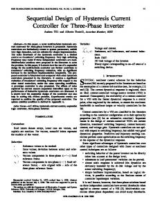
point of view of saving enormous loss of electrical energy in different home appliances, it seems better to implement the high frequency inverter topology [28-36].Series resonant inverters for high frequency induction heating and melting applications are started by themselves. A resonant circuit is needful for self –commutation. It is desired that the circuit is under damped. The capacitor required for under damping can be connected in series or in parallel with the load. For efficient forced commutation, reverse voltage must appear across the SCR in SCR based systems, which can be obtained from a charging circuit consisting of an inductor and a capacitor, called, the commutating components. They are connected to the load, so that the overall circuit becomes under damped and zero current is obtained [6-10]. Full bridge circuit is normally used for higher output power. Basic circuit is shown in the Figure 1. Four solid state switches are used and two switches are triggered simultaneously. Anti-parallel diodes are connected with the switch that allows the current to flow when the main switch is turned OFF.
Figure 1. Full Bridge Series Resonant Inverter The circuit is on when switches Q1 and Q4 are triggered simultaneously. The current flows for a half cycle of the resonant frequency and become zero when both switches Q1 and Q4 are turned off. When Q1 and Q4 stop conducting and switch Q2 and Q3 are not yet turned ON the current through the load reverses and is now carried by D1 and D4, the anti-parallel diodes that are connected with the respective switches. The voltage drops across diodes appear as a reverse bias across switch Q1 and Q4.Commutation circuit is not needed since duration of the reverse bias is more than the switch turn-off time, then switch Q1& Q4 get commutated naturally. This method of commutation is called load commutation. It is used in high frequency inverter for induction heating. Induction heating generators are resonant inverters which operate at high frequency and produces maximum current at resonance which is Hysteresis Current Control with Input Filter Design for High Frequency… (Debabrata Roy)
7652
ISSN: 2302-4046
sufficient to heat the work piece. Resonance occurs while the inductor and capacitor exchanges energy. Resonant inverters are electrical inverters based on resonant current oscillations [1216]. To from an under damped circuit in series resonant inverter the resonating components and switching devices are kept in series with the load. Due to natural characteristics of the circuit the current through the switching devices fall to zero.Short-circuit occurs when in voltagefed inverters, two switches of the same inverter leg is turned on at the same time.The time between the turning- off of one of these switches and the turning-on of the other is called deadtime. In this topology, anti-parallel diodes are necessary to allow inductor's current conduction when the opposite switches are turned-off. Basically semiconductor switching devices operate in Hard Switch Mode in various types of Pulse Width Modulation (PWM) DC-DC converters and DC-AC inverter. In this mode, switching devices turn on or off at specific current and specific voltage whenever switching occurs and switching losses are high. When the frequency is increased higher, greater the switching loss, which restricts the raise in frequency. Electromagnetic interference problem is also caused by switching loss because a large amount of d i a n d d v is generated. Switching loss can be calculated as:
dt
dt
Ps w
1 V s w I sw f s ( t o n t o ff ) ......................(5 ) 2
With increasing in switching frequency size of a transformer and filter is reduced, which helps build a smaller and lighter converter with high power density. But switching loss reduces the efficiency of the process, as more losses are generated at a higher frequency. Switching loss can be partly mitigated by connecting a snubber circuit parallel to the switching circuit. But the total amount of switching loss generated in the system remains the same. The loss avoided has been moved to the snubber circuit. At high switching frequency, higher efficiency can be obtained by making switching device to turn on or off at the zero crossing. This technique is called “soft switching,” which can be subdivided into two methods: Zero-Voltage Switching (ZVS) and Zero-Current Switching (ZCS). When the switching device voltage is set to zero right before turn on of switch, switching loss during turn on can be eliminate and this refers to ZVS. ZCS eliminates the turn-off switching loss by making current to zero in the circuit right before turning it off. Resonance condition which is obtained by L-C resonant circuit is used show that voltage and current in the switching circuit is made to zero. It is named as resonant converter topology. Resonant circuit absorbs the existing inductance in case of ZCS and it eliminates the volt surges during turn-off condition. Voltage surge during turn on of switching circuit is caused by an electric discharge of junction capacitance which cannot be avoided. This method causes switching loss (0.5CV2 f ) . ZCS, however, is free from this defect and makes both the existing inductance and capacitance be absorbed by the resonant circuit. This eliminates the chance of causing a surge in current at turn-off (caused by inductance) or turn- on (by capacitance) conditions. While substantially reducing the problem of EMI at high frequency ZVS, enables switching with loss less.Resonant inverters minimizes the switching loss and provides greater energy conversion efficiency to the power system, so it is widely used in a variety of industries. This is also the reason the inverter is adopted in the IH power system the typical diagram of series resonant inverter for induction heating [22-31]. Single phase AC supply (240V ,50 Hz ) is fed to rectifier which converts AC to DC and fed toinverter.Inverter generates high frequency AC current which is fed to load. In order to obtain maximum power transfer from source to load impedance matching is required since the load impedance will change during the heating cycle which might necessitate retuning or re matching to the source. Output from the inverter is connected to impedance matching transformer which matches the source impedance to the load impedance and thereby transfers maximum power from source to load [40-50]. The variables of the series resonant circuit are defined as follows: The resonant frequency
0
1 .....................( 6 ) LC
TELKOMNIKA Vol. 12, No. 11, November 2014: 7650 – 7658
ISSN: 2302-4046
TELKOMNIKA
7653
The characteristic impedance:
Z 0 0L
1
0c
.......................( 7 )
The load quality factor
Q
0L R
1 z 0 0cR R
L C .. ... ... ... ... ... ... ... ... ... ( 8 ) R
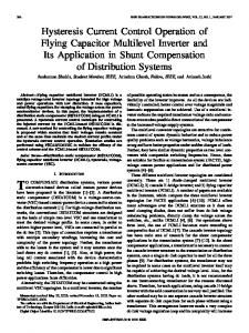
3. Suggested Topology Hysteresis current control is one such technique to regulate the output power for a varied range i.e. 5-55KHz. Hysteresis mode control was obtainable to the converter controller. It has been observed as a good alternative for regulating the current or voltage of a switching converter due to its fast dynamic characteristics and easy implementation. It has not only the excellent loop performance. It is also the instability can be prevented for all duty cycle since hysteretic control is basically based on the bounded process between upper and lower trip point. It controls the switching signals applied to inverter. In this technique reference wave is compared with Carrier wave and the switching signals are applied to the inverter with the intersection of these two waves. When this intersected wave reaches the upper band, switches S1 and S3 are turn on. When this reaches the lower band, switches S2 and S4 are turn on. With this changes in the switching state, output voltage is controlled and current is within the hysteresis band and thereby the output power is regulated for a wide range of heating cycle. Hysteresis current control is a closed loop control technique. The output current of the inverter is made to pathway the command current *I and maintain the error within the hysteresis band ( ) In the fig 2 when the error current is i i crosses the error band, inverters are switched to bring the output current within the error band. When the output current surpasses the upper band, it’s carried in to within the band ( ) by turning on the lower switch and turning off the upper switch. As a result, the voltage across the load changes from Vdc to 0 and the current decreases. Also when the output current goes below the lower band, the load is connected to Vdc by turning OFF the lower switch and turning ON the upper switch. As a result, the output voltage across the load changes from 0 to Vdc and the output current starts to build up. An optimal value of δ must be chosen to maintain a balance between the output current ripple and the switching losses and thereby eliminate specific harmonics. *
Figure 2. Hysteresis Band
Hysteresis Current Control with Input Filter Design for High Frequency… (Debabrata Roy)
7654
ISSN: 2302-4046
Output Power is calculated as:
Po u t V e ff I eff co s .....................(9 ) Effective Inverter voltage is given by:
Ton V eff V eff m ax .......................(1 0 ) T Effective inverter current is given by: I e ff
V
Po u t e ff c o s
Ton I e ff T
m ax
....(1 1)
To supply maximum power to the work piece operating frequency is match close to resonance frequency since at resonance frequency current is maximum. To control the phaseshift between two electric variables and reached the resonant frequency PLL systems are used. It is made of a phase detector and also a low-pass filter, and a Voltage Controlled Oscillator (VCO).A signal that is proportional to the phase shift between the two input signals is produced by the phase detector. Then, this signal is filtered through a low-pass filter and it obtains a DC voltage. It is proportional to the phase-shift. VCO generates an AC signal. Its frequency is proportional to its DC input voltage. The output of the VCO is connected with the input of the phase detector. The VCO adjusts the frequency until the output signal is matched to the input signal. PLL adjust the operating frequency until the phase shift between outputs current. Voltage is zero since in case of voltage fed series resonant inverter the voltage and current phase-shift is near to zero at resonant frequency.
4. Filter Design at Input Side The fixed band current controller gives good dynamic performance. Switching frequency is irregular and current ripple is large. In this situation within the sinusoidal band current controller the ripple can be varied with the current magnitude thereby reducing the current ripple content. In sinusoidal band as compared to fixed band current ripple content is less, but still the load current contains higher order harmonics that cause EMI problems and device heating. These high order harmonics are easily filtered out by using low pass filter on the input side. The Low pass filter (LC) with proposed configuration is shownin the Figure 3. LC filter design for the to eliminate the higher order harmonics, following calculations are made.
I ref 14.95A b) Load Parameter R 1 , L 97.1 H c) Frequency= 55KHz
a)
The inductive reactance for the nth harmonic voltage is following formula
X L j 2 n 55 10 3 97.1 10 6 j 33.555 n The impedance for the nth harmonic voltage is obtained by:
Z n 12 (33.555 n) 2
1/ 2
n =order of harmonics. The nth and higher order harmonics would be reduced significantly if the filter impedance is much smaller than that of load, and a ratio of 1:10 is normally adequate, TELKOMNIKA Vol. 12, No. 11, November 2014: 7650 – 7658
ISSN: 2302-4046
TELKOMNIKA
7655
Z n 10 X c Where the filter impedance is: 2 2 X e X i X c
1/2
X e 2 n 50 L (1 / 2 n 50 C ) 2 2
1/2
Putting L=0, above equation becomes:
1 2 (3 3 .5 5 5 n ) 2
1/ 2
10 / X c
The value of filter capacitance C can be found from equation by considering L 0 and the value of C 0.22uF .Similarly substituting the value of C in Equation (19) the value of L 97.1uH for Single phase. Now by taking different values of Load parameters the value of L and C values can be easily calculated.
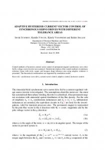
5. Simulation Result Series resonant inverter with hysteresis current control is analyzed and simulated using PSIM. Sufficient Current is generated which is used to heat the work piece with the load resistance of 1ohm. Inverter switching frequency is made close to resonance frequency to get the current response at maximum. Fig 4shows the output voltage and output current at the work piece.
Figure 3. Low-pass Filter with LC Components in High Frequency Inverter Inverter output voltage at the work piece is 450V with load resistance of 1.Q. Inverter output current at the work piece is15A which is sufficient to heat the work piece.
Hysteresis Current Control with Input Filter Design for High Frequency… (Debabrata Roy)
7656
ISSN: 2302-4046
Figure 4. Output Voltage and Output Current
6. Conclusion This paper describes a high frequency series resonant inverter for induction heating application in domestic and industrial area. Power control is done by hysteresis current control method and provides good response for 5–55 kHz range. Soft switching techniques are employed to minimize switching losses. Phase locked loop which matches switching frequency to resonant frequency in order to achieve the maximum response at resonance. Thus the high frequency series resonant inverter with hysteresis current control provides best response for industrial and domestic induction heating. Moreover, proper input LC filter design reduces harmonic injection in the power supply line.
References [1] Pradip Kumar Sadhu, Debabrata Roy, NItai Pal, Sourish Sanyal. Selection of Appropriate Semiconductor Switches for Induction Heated Pipe-Line using High Frequency Full Bridge Inverter. International Journal of Power Electronics and Drive Systems. 2014; 5(1): 112-118. [2] Omar El-Nakeeb, Mostafa I Marei, Ahmed A El-Sattar. A High Frequency modular Resonant Converter for the Induction Heating. International Journal of Emerging Technology and Advanced Engineering. ISSN 2250-2459, ISO 9001: 2008 Certified Journal. 2013; 3(2): 2013. [3] PK Sadhu, RN Chakrabarti, SP Chowdhury. An improved inverter circuit arrangement. Patent No. 69/Cal/2001, Patent Office – Government of India. [4] PK Sadhu, RN Chakrabarti, SP Chowdhury. A heating apparatus using high frequency induction heating,” Indian Patent No. 216361 (68/Cal/2001), Patent Office- Government of India. [5] PK Sadhu, N Pal, A Bhattacharya. Choice of Semiconductor Switches for Energy Efficient Induction Heated Pipe-line using H. F. Mirror Inverter. Proceedings of the International Multi Conference of Engineers and Computer Scientists. IMECS 2012, Hong Kong. 2012; II. [6] MK Rahmat, S Jovanovic, KL Lo. Reliability and Availability Modelling of Uninterruptible Power Supply Systems Using Monte-Carlo Simulation, International Review of Electrical Engineering (IREE). 2006; 1(3): 374 – 380. [7] PK Sadhu, N Pal, D Sinha, A Bandyopadhyay. Energy Efficient Induction Heated Cooking – Range using MCT baesd Hybrid Resonant Converter. IEEE Proceeding of the 2nd International Conference on Computer and Automation Engineering (ICCAE 2010). 2010; 5: 637-641. [8] PK Sadhu, N Pal, R Chakrabarti, DK Mittra. A dynamic model for the simulation of induction cooktop,” J. Industrial Engineering. 2006; XXXV(6): 37-41. [9] N Pal, PK Sadhu, RN Chakrabarti. A Comparative Study of HF Mirror Inverter for Induction Cooker through Real-time and PSPICE Simulation. J. Institution of Engineers (I). 2006; 86: 268-274.
TELKOMNIKA Vol. 12, No. 11, November 2014: 7650 – 7658
TELKOMNIKA
ISSN: 2302-4046
7657
[10] PK Sadhu, N Jana, RN Chakrabarti, DK Mittra. A Unique Induction Heated Cooking Appliances Range Using Hybrid Resonant Converter. Int. J. of Circuits, Systems and Computers, World Scientific. 2005; 14(3): 619-630. [11] PK Sadhu, RN Chakrabarti, SP Chowdhury. A new generation fluid heating in non–metallic pipe–line using BJT and IGBT. J. Institution of Engineers (I). 2002; 82: 273-280. [12] PK Sadhu, RN Chakrabarti, K Mukherjee, SP Chowdhury, BM Karan. A new generation microprocessor based radio-frequency operated induction heating for sterilization and boiler plant. J. IEEMA. 2002; XXII(2): 36 – 48. [13] PK Sadhu, RN Chakrabarti, K Mukherjee, SP Chowdhury, BM Karan. High efficient contamination free clean heat production. Indian Journal of Engineering & Materials Sciences, National Institute of Science Communication, New Delhi. 2002; 9: 172-176. [14] PK Sadhu, RN Chakrabarti, K Mukherjee, SP Chowdhury, BM Karan. Microprocessor-based energy efficient sterilization for surgical instrument using a new generation inverter topology. J. Energy, Heat & Mass Transfer. 2001; 23(1): 39-53. [15] MD Singh, KB Khanchandani. Power Electronics. 2nd. Edition, Tata-McGraw-Hill Edn. Pvt. Ltd., ISBN: 978-0-07-058389[16] A Fewson. Introduction to Power Electronics. 1998, Oxford University Press Inc., New York. [17] PC Sen. Power Electronics. 16th. Reprint, 2001, Tata-McGraw-Hill, ISBN: 0-07-462400-8 [18] BD Bedford, RG Hoft. Principle of Inverter Circuits. New York, John Wiley & sons, 1964. [19] MH Rashid. Power Electronics Circuits, Devices, and Applications. Third Edition, Dorling Kindersley Pvt. Ltd. [20] RC Dugan, MF McGranaghan, S Santoso, HW Beaty. Electrical Power Systems Qualit. 2nd. Edition, Tata-McGraw-Hill, ISBN: 978-0-07-026462-5 [21] VK Khanna. Insulated Gate Bipolar Transistor (IGBT): Theory And Design. IEEE Press, WileyInterscience. [22] PK Sadhu, N Pal, A Bandyopadhyay, D Sinha. Review of Induction Cooking – a Health Hazards Free Tool to Improve Energy Efficiency as Compared to Microwave Oven. IEEE Proceeding of the 2nd International Conference on Computer and Automation Engineering (ICCAE 2010). 2010; 5: 650-654. [23] PK Sadhu, N Pal, RN Chakrabarti, TK Chatterjee. Performance analysis of HF mirror inverter for energy efficient induction cooker appliance range. Int. Conf. on Modelling and simulation MS’07, University of Calcutta. 2007: 444-448. [24] S Llorente, F Monterde, JM Burdio, J Acero. A comparative study of resonant inverter topologies used in induction cooker. IEEE Applied Power Electronics Conf. (APEC) Rec., 2002: 1168-1174. [25] Iran Azim, Habibur, Rahman. Analysis & Simulationof Total Harmonic Distortion in Hysteresis Inverter. International Journal of Advanced Research in Computer Engineering& Technology (IJARCET). 2013; 2(3): 574-578. [26] MM Inallou, J Nanosci. International journal of Mechatronics. Electrical and Computer Technology. 2012; 3(6): 63-75. [27] AlirezaNamadmalan, JavadShokrollahiMoghani. Self-Oscillating Switching Technique for Current Source Parallel Resonant Induction Heating Systems. Journal of Power Electronics. 2012; 12(6). [28] AJ Onah. Harmonics: Generation and Suppression in AC System Networks. Nigerian Journal of Technology. 2012; 31(3): 293-299. [29] Diego Puyal, Carlos Bernal, José M Burdío, JesúsAcero, Ignacio Millán, Versatile. High-Frequency Inverter Module for Large-Signal Inductive Loads Characterization Up to 1.5 MHz and 7 kW IEEE Transactions On Power Electronics. 2008; 23(1): 75-86. [30] GP Sanat, Editor. Introduction of Mechatronics", Universal Scientific Organization Publishers, Austria, Enns. 2013: 163-275. [31] Imran Azim, Habibur Rahman. HarmonicsReductionof a Single Phase Half Bridge Inverter. Global Journal of Research in Engineering. 2013; 13(4)1: 9-12. [32] LA Barragan, JM Burdio, JI Artigas, D Navarro, J Acero, D Puyal. Efficiency optimization in ZVS series resonant inverters with asymmetrical voltage-cancellation control. IEEE Trans. Power Elec-tron., 2005; 20(5): 1036–1044. [33] Y Sozer, DA Torrey, S Reva. New inverter output filter topology for PWM motor drives. Power Electronics, IEEE Transactions. 2000; 15(6): 1007–1017. [34] A Suresh, S Rama Reddy. Series and Parallel Resonant Inverter Fed Ferromagnetic Load-A Comparative Analysis. International Conference on Emerging Trends in Computer and Image Processing (ICETCIP'2011) Bangkok. 2011. [35] DE Steeper, RP Stratford. Reactive Compensation and Harmonic Suppression for Industrial Power Systems Using Thyristor Converters. IEEE Transactions on Industry Applications. 1976; 12: 232-254. [36] Diego Puyal, Carlos Bernal, José M. Burdío, JesúsAcero, Ignacio Millán, Versatile High-Frequency Inverter Module for Large-Signal Inductive Loads Characterization Up to 1.5 MHz and 7 kW. IEEE Transactions On Power Electronics. 2008; 23(1): 75-86 [37] J Kim, J Choi, H Hong. Output LC filter design of voltage source inverter considering the performance of controller. Power System Technology., Proceedings. 2000; 3: 1659–1664.
Hysteresis Current Control with Input Filter Design for High Frequency… (Debabrata Roy)
7658
ISSN: 2302-4046
[38] Jose M Burdio, Fernando Monterde, Jose R Garcia, Luis A Barragan, Abelardo Martinez. A two-output series-resonant inverter for induction-heating cooking appliances. IEEE Trans. Power Electron., 2005; 20(4): 815-822. [39] WK Chen. Linear Networks and Systems.Belmont, CA: Wadsworth. 1993: 123–135. [40] GH Bode, DG Holmes. Load Independent Hysteresis Current Control of a Three Level Single Phase Inverter with Constant Switching Frequency. Conf. Rec. IEEE Power Electronics Specialists Conf. 2001; 14-19. [41] Calais, VG Agelidis, LJ Borle, MS Dymond. A Transformer less Five Level Cascaded Inverter Based Single Phase Photovoltaic System. Conf. Rec. IEEE Power Electronics Specialists Conf. 2000; 1173-1178. [42] GH Bode, DG Holmes. Implementation of Three Level Hysteresis Current Control for Single Phase Voltage Source Inverter. Conf. Rec. IEEE Power Electronics Specialists Conf. 2000; 33-38. [43] M Lafoz, IJ Iglesias, C Veganzones, M Visiers. A Novel Double Hysteresis-Band Control for ThreeLevel Voltage Source Inverter. Conf. Rec. IEEE Power Electronics Specialists Conf. 2000; 21-26. [44] KA Corzine. A Hysteresis Current–Regulated Control for Multi- Level Drives. IEEE Transactions on Energy Conversion. 2000; 15(2): 169-175. [45] G Sinha, TA Lipo. Rectifier Current Regulation in Four Level Drives. Conf. Rec. IEEE Applied Power Electronics Conf. and Exposition. 1997; 320–326. [46] T Ishida, K Matsuse, K Sugita, L Huang, K Sasagawa. DC Voltage Control Strategy for a Five-Level Converter. IEEE Transactions on Power Electronics. 2000; 15(3): 508-515. [47] NJ Park, DY Lee, DS Hyun. A power-controlscheme with constant switching frequency in class-D inverterfor induction-heating jar application. IEEE Trans. Ind.Electron., 2007; 54(3): 1252–1260. [48] S Faucher, F Forest, JY Gaspard, JJ Huselstein, C Joubert, D Montloup. Frequency-synchronized resonant converters for the supply of multiwinding coils in induction cooking appliances. IEEE Trans. Ind. Electron., 2007; 54(1): 441–452. [49] JM Espí, EJ Dede, R García-Gil, J Castelló. Design of the L–LC resonant inverter for induction heating based on its equivalent SRI. IEEE Trans. Ind. Electron., 2007; 54(6): 3178–3187. [50] ZM Ye, PK Jain, PC Sen. Full-bridge resonant inverter with modified PSM for HFAC power distribution systems. IEEE Trans. Ind. Electron., 2007; 54(5): 2831–2845. [51] Han Yang. A Pedagogical Approach for Modeling and Simulation of Switching Mode DC-DC Converters for Power Electronics Course. TELKOMNIKA Indonesian Journal of Electrical Engineering. 2012; 10(6): 1319-1326. [52] T Sutikno, A Jidin, NRN. Idris. New Approach FPGA-Based Implementation of Discontinuous SVPWM. Turk J Elec Eng & Comp Sci. 2010; 18(4): 499-514. [53] Tole Sutikno, Nik Rumzi Nik Idris, Aiman Zakwan Jidin, Auzani Jidin. A Model of FPGA-based Direct Torque Controller. TELKOMNIKA Indonesian Journal of Electrical Engineering. 2013; 11(2): 747-753.
TELKOMNIKA Vol. 12, No. 11, November 2014: 7650 – 7658