Interpolated Linear Precoding and Space-Frequency Coding for MIMO-OFDM Systems Eunmo Kang and Akbar M. Sayeed Department of Electrical and Computer Engineering University of Wisconsin-Madison
[email protected],
[email protected]
Abstract—We investigate the design of space-frequency codes and efficient feedback-aided precoding schemes for multipleinput multiple-output orthogonal frequency division multiplexing (MIMO-OFDM) systems. Inspired by the statistical structure of the MIMO-OFDM channel matrix, the proposed transceiver structure consists of two components: i) a fixed space-frequency code, and ii) a set of spatial precoding matrices that are adapted based on limited feedback from the receiver. For the fixed component, we propose a structured space-frequency coding scheme that spreads the source symbols across space and frequency. The space-frequency coded symbols are then processed with a spatial precoding matrix for each OFDM tone before transmission. The spatial precoding matrices use the limited feedback from the receiver to adapt the spatial directions and corresponding power allocation for different spatial symbols, in order to improve both the mutual information and error rate. Since the spatial channel statistics are invariant across frequency, one codebook of spatial precoding matrices suffices for all OFDM tones. This codebook is designed using a systematic algorithm that we had previously developed for narrowband spatially correlated MIMO channels. Finally, to reduce the computational complexity at the receiver and the amount of feedback to the transmitter, we propose a new interpolation algorithm in which the codebook indices are fed back to the transmitter for a subset of tones – precoding matrices for the other tones are computed at the transmitter using the precoding matrices for tones in the subset.
I. I NTRODUCTION Orthogonal frequency division multiplexing (OFDM) is a widely adopted method for high rate communications and is incorporated in many standards including wireless local area network (IEEE 802.11a/g) and wireless metropolitan area network (IEEE 802.16e) standards. In order to provide higher data rate and better error performance, the transmitter and the receiver can be equipped with multiple antennas, forming multiple-input multiple-output (MIMO) systems. We highlight some of the work on MIMO-OFDM below. Maximum diversity gain attainable with MIMO-OFDM systems was derived in [1], [2]. The full or significant portion of the diversity gain can be achieved by space-frequency codes [3], [4] or space-time-frequency codes [5]1 . The authors of [6] investigated capacity-optimal input covariance matrices for MIMO-OFDM systems when only channel statistics are available at the transmitter, while the case where perfect channel state information is available at the transmitter was considered in [7]. 1 This
work also proposed the frequency grouping technique, which we adopted as a part of the proposed space-frequency codes.
s 1(1) .. . s N (1) Tt s 1(2)
.. . .. . .. .
QNT QNT
.. .
.. .
T
s N (N) T
~ x(1)
.. .
.. .
.. .
.. . .. .
.. .
Π
.. .
NNT NNT
.. .
G
.. . s N (Q) .. T . s 1(N−Q+1) .. . s N (N−Q+1) s 1(N−Q+2) .. .
~ s(1)
.. .
G QNT QNT
.. .
.. .
.. .
.. .
~ s(N)
~ x(N)
x(1) ^ D(1) NT NT .. .
.. .
^ D(Q) NT NT .. .
.. .
^ D(N−Q+1) NT NT ...
.. .
^ D(N) NT NT
.. .
.. .
.. .
.. .
^ U(1) NT NT .. .
.. .
^ U(Q) NT NT .. .
.. .
.. .
^ .. U(N−Q+1) . NT NT .. . ^ U(N) NT NT
.. .
.. . x(N)
.. .
IFFT
.. .
N N
.. .
CP & P/S
Ant. 1
.. .
.. . .. . .. .
IFFT
.. .
N N
CP & P/S
Ant. N T
Feedback from Receiver
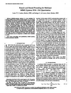
Fig. 1. MIMO-OFDM transmitter with fixed space-frequency coding (G and ˆ ˆ Π) and feedback-aided precoding (U(n) and D(n))
In practice, we can convey only limited amount of information through a feedback channel. In order to use feedback information efficiently and to reduce the feedback amount, two directions have been pursued. One is to design efficient precoder codebooks matched to channel statistics [8], [9]. The other is to employ interpolation – the transmitter gets feedback information for a subset of tones and uses interpolation for the tones not in the subset [10], [11]. The contribution of this paper is two-fold. We propose 1) space-frequency codes that are based on threaded algebraic space-time codes [12] but with a modification that becomes necessary when power allocation is employed (Section III), and 2) new interpolation algorithm designed for a system incorporating power allocation – previous algorithms are for equal-power transmission schemes (Section IV). II. S YSTEM AND C HANNEL M ODEL We consider a MIMO-OFDM system with N subcarriers (tones) equipped with uniform linear arrays (ULAs) consisting of NT transmit and NR receive antennas. We assume that the maximum channel delay is ND < N (in taps) and cyclic prefix of length NCP ≥ ND is used. Then the channel matrix corresponding to the n-th tone is the discrete Fourier transform ˜ (DFT) of the channel impulse response matrices H(d), d= 0, 1, . . . , ND , ND 1 X −j2π nd ˜ N . H(d)e H(n) = √ N d=0
(NR × NT )
The input-output relationship for the n-th tone can be written as y(n) =
√
SNR H(n)x(n) + n(n), n = 1, . . . , N
where x(n) is the NT × 1 transmitted signal vector with tr(E[x(n)x(n)H ]) = 1, y(n) is the NR × 1 received signal vector, and n(n) ∼ CN (0, INR ) is the NR × 1 noise vector, i.e. complex Gaussian vector with zero mean and the identity covariance matrix. The channel matrix H(n) is assumed zero mean and the covariance matrix is discussed in detail later in this section. It is often convenient to stack these vectors and matrices corresponding to each tone in order to represent the entire system as ¯= y
√
¯x+n ¯ SNR H¯
in which
½ ¾ 1 d 1 SD,d = ` : − ≤ τ` − < 2W W 2W ½ ¾ r 1 r 1 SR,r = ` : − ≤ θR,` < + NR 2NR NR 2NR ¾ ½ t 1 t 1 . ST,t = ` : − ≤ θT,` < + NT 2NT NT 2NT
Since different entries of {HV (r, t, d)} correspond to disjoint set of paths, they can be assumed approximately independent, but not identically distributed in general – we denote the variance of each entry by Ψ(r, t, d) = E[|HV (r, t, d)|2 ]. This model induces the following spatial and spectral correlation E [Hr,t (n)H
0 ∗
(n ) ] =
ND X
e
j2π(n0 −n)d N
·
d=0
(1)
NR X NT X
where
Ψ(˜ r, t˜, d)e
j2π(r−r 0 )˜ r NR
e
˜ j2π(t−t0 )t NT
.
r˜=1 t˜=1
£ ¤T ¯ = y(1)T y(2)T . . . y(N )T y £ ¤T ¯ = x(1)T x(2)T . . . x(N )T x £ ¤T ¯ = n(1)T n(2)T . . . n(N )T n ¯ = diag (H(1), H(2), . . . , H(N )) . H
(N NR × 1) (N NT × 1) (N NR × 1) (N NR × N NT )
The statistical characteristics of the channel matrix H(n) for the n-th tone are dictated by those of the time-domain ˜ impulse response matrices H(d). We assume that there are NP paths, and use β` ∈ C, τ` , θT,` ∈ [0, 1] and θR,` ∈ [0, 1] to represent the complex path gain, path delay (in seconds), normalized2 angle of departure (AoD) and normalized angle of arrival (AoA) of the `-th path, respectively. The array steering and response vectors are £ ¤T denoted by aT (θT ) = 1 ej2πθT ej4πθT . . . ej2π(NT −1)θT £ ¤T and aR (θR ) = 1 ej2πθR ej4πθR . . . ej2π(NR −1)θR . Then, uniform sampling in delay and AoD/AoA yields the following representation of H(n), called virtual channel model [13] NP n 1 X H(n) = √ β` aR (θR,` )aT (θT,` )H e−j2πτ` T N `=1 µ µ ¶ ¶H ND X NR X NT 1 X r t ≈√ HV (r, t, d)aR aT · NR NT N r=1 t=1 d=0
dn
e−j2π N
(2)
where
Setting n = n0 , one can easily observe that every tone has the same covariance matrix R = E[vec(H(n))vec(H(n))H ] as well as the same transmit covariance matrix RT = E[H(n)H H(n)]. (vec(·) denotes the column stacking operator.) III. C LOSED - LOOP S PACE -F REQUENCY- CODED MIMO-OFDM Feedback-aided precoding can greatly improve the capacity and error performance of MIMO-OFDM systems. With linear precoding, the system equation in (1) changes to √ ¯ W¯ ¯ s+n ¯ = SNRH ¯, y ¯ is the N NT × N NT matrix with tr(W ¯W ¯ H) = where W N NT and ¯s is the N NT × 1 source symbol vector3 with tr(E[¯s(n)¯s(n)H ]) = N . We investigate the extreme cases – where the channel states are perfectly known at the transmitter and where only channel statistics are known at the transmitter – and then consider the finite-rate feedback cases. A. Perfect Feedback and Statistical Feedback Cases When the channel states are perfectly known at the transmitter, it is well known that SVD of the channel matrix, H(n) = UH (n)DH (n)VH (n)H , n = 1, . . . , N , and waterfilling yields the capacity-optimal precoding matrix: ¯ = diag(VH (1) VH (2) . . . VH (N )) W diag(DW (1) DW (2) . . . DW (N ))ΥH
(3)
where Υ is an arbitrary unitary matrix and HV (r, t, d) =
X
β`
`∈SD,d ∩SR,r ∩ST ,t
θ˜ ∈ [−90, 90] and normalized angle θ ∈ [0, 1] are related by ˜ ˜ θ = θ/180 for 0 ≤ θ˜ ≤ 90 and θ = θ/180 + 1 for −90 ≤ θ˜ < 0. Note that aT (θT ) and aR (θR ) are periodic in angles with unit period. 2 Angle
r 0 ,t0
DW (n) = õ diag µ−
1 [DH (n)]1,1
¶ 12 +
µ ,..., µ −
1 [DH (n)]NT ,NT
¶ 12 ! +
3 If less than N symbols per tone are transmitted for each channel use, T ¯ and the height of ¯ then the width of W s should be reduced accordingly.
first second column column
in which subscript (·)+ denotes the max(·, 0) operator. Another extreme case is when the transmitter knows only channel statistics, i.e. mean and variance. In this case, the capacity-optimal precoding matrix has the eigenvectors of the transmit covariance matrix as its left singular vectors if we use Kronecker channel model or virtual channel model [14]. When we place no structure on the channel matrix, a near-optimal precoding matrix can be easily obtained by finding the one that maximizes the Jensen-upperbound of capacity and is given as [15] ¯ = (IN ⊗ Vst )· W " õ IN ⊗ diag
µ−
1
¶ 12
λst,1
µ ,..., µ −
+
1 λst,NT
¶ 12 !#
ΥH
u(1) u(2) u(3) u(4) Fig. 2. bit(s).
third column
matrix index
u(1,1)
u(1,1,1)
1
u(1,2)
u(1,2,1)
2
u(2,1)
u(2,1,1)
3
u(2,2)
u(2,2,1)
4
u(3,1)
u(3,1,1)
5
u(3,2)
u(3,2,1)
6
u(4,1)
u(4,1,1)
7
u(4,2)
u(4,2,1)
8
Unitary codebook U of size 8 (=2bU ). b1 = 2, b2 = 1, b3 = 0
+
where Vst is the eigenmatrix of RT = Vst Λst VstH and λst,t is the t-th eigenvalue. Note that in both cases, the right singular vectors (Υ) does not affect mutual information, but does affect error performance. B. Finite-rate Feedback Case When btotal bits of feedback information is available for each channel use, the receiver can choose a precoding matrix ¯ from a precoder codebook of size 2btotal , which can be W very large. However, the block diagonal structures present in (3) suggest a simpler approach: a per-tone precoding scheme (see Fig. 1). That is, we allocate b = btotal /N bits to each tone, out of which bU bits are used to approximate the right singular matrix VH (n) of the channel matrix with a codeword ˆ U(n) in the unitary codebook U , |U| = 2bU . The remaining bD = b − bU bits are used to approximate the power allocation ˆ matrix DW (n) with a codeword D(n) in the power allocation codebook D, |D| = 2bD . As noted at the end of Section II, statistical characteristics are identical for every tone, i.e. H(n) ∼ CN (0, R), ∀n, implying we need to design only one ˆ set of a unitary codebook U for U(n) and a diagonal codebook ˆ D for D(n) and use it for all tones – we do not have to design N sets of codebooks each optimized to each tone. Now we can adopt the precoder codebook design algorithm developed for narrowband correlated MIMO channels that we proposed in [9]. The algorithm constructs U systematically based on R since using numerical optimization to compute 2bU (NT2 −NT ) variables is hard; however D involving 2bD (NT − 1) variables can be built numerically. We provide a brief summary of the algorithm [9] below.
~ s(1) ~ s(2)
.. . ~ s(Q) ~ s(Q+1) ~ s(Q+2) .. . ~ s(2Q) ~ s(2Q+1) ~ s(2Q+2) .. . ~ s(3Q) ~ s(3Q+1) ~ s(3Q+2) .. . ~ s(4Q)
.. . ~ s(N−Q+1) ~ s(N−Q+2) .. . ~ s(N)
Fig. 3.
~ x(1) ~ x(2) ~ x(3) ~ x(4) .. . ~ x(N/Q) ~ x(N/Q+1) ~ x(N/Q+2) ~ x(N/Q+3) ~ x(N/Q+4) .. . ~ x(2N/Q) .. . ~ x(N−N/Q+1) ~ x(N−N/Q+2) ~ x(N−N/Q+3) ~ x(N−N/Q+4) .. . ~ x(N)
Permutation by Π
b2
C. Precoder Codebook Design Algorithm
{u(n1 ,1) , . . . , u(n1 ,2 ) }, to be used in the second column. It is also obtained by skewing a reference codebook of length (1) (2b2 ) NT −1 vectors {cNT −1×1 , . . . , cNT −1×1 } and placing them in the null space of the subspace spanned by u(n1 ) . We proceed in this way until the second-to-last column is taken care of – the last column is determined automatically (bNT = 0) due to unitariness. Since bU bits are the budget for specifying beamdirections, we should have b1 + b2 + · · · + bNT = bU . This algorithm leads to the tree-structured codebook U shown in Fig. 2.
The unitary codebook U is constructed by designing a set b1 of length-NT vectors, {u(1) , . . . , u(2 ) }, whose role is to approximate the first column of VH (n). We design the set (1) (2b1 ) by skewing a reference vector codebook {cNT ×1 , . . . , cNT ×1 } (which is designed for beamforming in i.i.d. channels) through a channel statistics-dependent transform so that the skewed vectors are denser along the statistically dominant eigenvectors than along other directions. Then for each vector u(n1 ) in the set, we find the second set of length-NT vectors,
The diagonal codebook D can be designed numerically using vector quatization algorithms (e.g. generalized Llyod algorithm). First we generate a training set {DW (n)} which is computed from a number (e.g. 100 · 2bD ) of randomly generated channel realizations {H(n)} (according to CN (0, R)). A vector quantization algorithm is applied to the vectors consisting of the diagonal entries of the training set {DW (n)}. Representative vectors returned by the quantization algorithm constitute the diagonal entries of the codeword matrices in D.
D. Space-Frequency Coding In this section we design a fixed space-frequency codes providing high diversity gain and manageable decoding complexity. Choosing any unitary matrix as Υ yields the same mutual information, but it has significant impact on error performance. It can be seen from the fact that without spreading source symbols across space and frequency (i.e. Υ = I), the diversity gain is only NR which is significantly less than the maximum diversity gain min(N NR , NP NT NR ) [1], [2]. In order to maintain a manageable level of complexity for maximum-likelihood decoding, we divide the N NT source symbols into G = N/Q groups of NT Q symbols each. Then we code source symbols in each group across space and frequency applying threaded algebraic space-time (TAST) block codes since they possess the best or close to best error performance among space-time block codes [12]. As an example, a modified TAST code for the NT = Q = 4 case is shown below [9] [˜s(1) ˜s(2) ˜s(3) ˜s(4)] = 3 2 z1 (1) θ 4 z2 (4) θ 4 z3 (3) 3 1 θ 4 z1 (2) z2 (1) θ 4 z3 (4) Γ 2 1 θ 4 z1 (3) θ 4 z2 (2) z3 (1) 3 2 1 4 4 4 θ z1 (4) θ z2 (3) θ z3 (2)
1 4
θ z4 (2) 2 θ 4 z4 (3) 3 θ 4 z4 (4) z4 (1)
(4)
where [z1 (n) z2 (n) z3 (n) z4 (n)]T = Φs(n), n = 1, 2, 3, 4, is the rotated symbol vector, and θ is a unit-norm scaling parameter for ensuring full-diversity of the TAST code. The unitary matrix Γ ensures that each source symbol interacts with every channel coefficient even when the power allocation ˆ matrix DW (n) or D(n) mutes some spatial streams or rows (see [9] for details on Γ). It is convenient h i h to write (4) in a veci T
T
T T T T tor form as ˜s (1) . . . ˜s (4) = G s (1) . . . s (4) , ˜ ˜ where G =(IQ ⊗ Γ)G, and G is the NT Q × NT Q generator matrix for TAST codes incorporating the rotation matrix Φ and scaling parameter θ. Finally, the coded symbols are fed to the permutation matrix Π, whose role is to place symbol vectors belonging to the same group far apart in the subcarrier domain as shown in Fig. 3, so that each symbol experiences independent subchannels instead of highly correlated ones. See Fig. 1 for an overall structure.
IV. R EDUCING F EEDBACK B Y I NTERPOLATION One can reduce feedback burden by adopting interpolation techniques. That is, instead of specifying precoding matrices ˆ ˆ U(n) and D(n) for every tone, n = 1, . . . , N , the receiver informs the transmitter of the precoding matrices corresponding to only a subset of tones, n = K, 2K, . . . , N , assuming N/K is an integer for convenience. Precoding matrices for tones not in the subset are computed by interpolating those of the two adjacent tones in the subset – for example, precoding matrices for tones n = K + 1, K + 2, . . . , 2K − 1 are interpolated using those for n = K and n = 2K. Since H(n) is periodic in n with period N , precoding matrices for the first K −1 tones can be obtained from the tones n = N and n = K. We discuss two existing methods and then propose a new algorithm.
The linear interpolation technique proposed in [10] for beamforming (single stream) and spatial multiplexing (NS streams) schemes forms NT × NS interpolated spatial multiplexing matrices Ulin (`K + m) as follows. First, it computes ˜ lin (`K + m) = αm U(`K) ˆ ˆ U + βm U((` + 1)K)Q(`), ` = 0, 1, . . . , N/K − 1, m = 1, 2, . . . , K − 1 where αm = 1 − m/K, βm = m/K, and the unitary matrix Q(`) is determined by the receiver according to a certain criterion and fed back to the transmitter. Then it is converted to a semi-unitary matrix as Ulin (`K + m) = ´−1/2 ³ ˜ lin (`K + m) ˜ lin (`K + m) U ˜ lin (`K + m)H U . U More recently, a geodesic-based interpolation algorithm was proposed for spatial multiplexing schemes [11]. It eliminates the need to calculate and feedback the Q(`) matrix. It forms the NT × NS interpolated matrix Ugeo (`K + m) as Ugeo (`K + m) =A(`) cos(mΣ) − B(`) sin(mΣ)
(5)
ˆ ˆ where A(`) = U(`K)U, and B(`) = [U(`K)U ˆ cos(KΣ)−U((` + 1)K)V] sin−1 (KΣ), in which U and V H ˆ ˆ U((`+1)K) = UDVH , and come from the SVD of U(`K) −1 Σ = (1/N ) cos (D). Unfortunately, we cannot use the existing algorithms for the proposed system incorporating power allocation because those algorithms are designed for beamforming and spatial multiplexing schemes which allocate same power for every beam-direction. Specifically, those algorithms produce only interpolated semi-unitary matrices, but not interpolated power allocation matrices. Moreover, the geodesic interpolation algorithm does not observe the ordering of columns – if U happens to be the anti-identity matrix, then Ugeo (`K +1) will ˆ be close to U(`K) but with reverse column ordering. It is very problematic since the beam-direction that should get the most transmit power will receive the least transmit power (diagonal entries of power allocation matrices are in decreasing order). Hence we propose a new interpolation algorithm that addresses the above problems. The proposed algorithm preserves the ordering of columns, and produces both beam-direction matrix and power allocation matrix, without requiring additional information such as Q(`). The key idea is to perform interpolation in the covariance matrix domain, taking into account both beam-directions and power allocation. First, we form Rcov (`K + m) = αm Rcov (`K) + βm Rcov ((` + 1)K) where αm = 1 − m/K, βm = m/K, and Rcov (`K) = 2ˆ ˆ ˆ U(`K) D(`K) U(`K)H . We can think of Rcov (`K) as a rough estimate of the short-term transmit covariance matrix for the `K-th tone, based on the current channel state H(`K). Then the interpolated matrices Ucov (`K + m) and Dcov (`K + m) are obtained by applying eigen-decomposition to the interpolated matrix Rcov (`K + m) as Rcov (`K + m) = Ucov (`K + m)Dcov (`K + m)2 Ucov (`K + m)H .
−1
10
25
20
Perfect CSIT (every tone) Perfect CSIT (proposed interpl.) SM (two streams) (every tone) SM (two stremas) (geodesic interpl.) −2
Bit Error Rate
10
Capacity
15
10
−3
10
−4
10 5
0 −10
−5
−5
Fig. 4.
0
5 SNR (dB)
10
15
10
20
Impact of interpolation on capacity
One can easily check that when m is close to zero, Ucov (`K + m) and Dcov (`K + m) are close to those of the `K-th tone, and when m is close to K, to those of the (` + 1)K-th tone. V. N UMERICAL R ESULTS We present numerical results to illustrate the benefit of interpolation and the feedback-aided precoding. We use the following configurations: NT = NR = Q = 4, N = 64 tones. Symbols are taken from a BPSK constellation and maximum likelihood decoding is used. For the modified TAST codes in (4), we use θ = ejπ/12 and Γ is the Vandermonde matrix whose columns are powers of [ejβ ej(β+π/2) ej(β+π) ej(β+3π/2) ]T with β = 0.97. In Fig. 4, for spatially i.i.d. channels (R = INT NR ), we compare the capacity when the transmitter knows perfect channel states of every tone (refer to (3)) with the mutual information obtained by interpolation with K = 8. In generating spectral correlation, we assume ND = 8, and for all iR and iT we set Ψ(iR , iT , d) = 8, if 1 ≤ d ≤ 8, and Ψ(iR , iT , d) = 0, if 9 ≤ d ≤ 64. The lower two curves correspond to the spatial multiplexing scheme, which transmits two independent source streams with equal transmit power along the beam-directions specified by the first two right singular vectors of H(n). Fig. 5 shows the bit error rate of various schemes in spatially correlated channels. We assumed ND = 4 and bU = 8 (b1 = 5, b2 = 3, b3 = b4 = 0) and bD = 0. Spatial correlation is as follows: for all iR = 1, 2, . . . , NR and d = 1, 2, 3, 4, we have Ψ(iR , 1, d) = 38.4, Ψ(iR , 2, d) = 16, Ψ(iR , 3, d) = 6.4, Ψ(iR , 4, d) = 3.2; and Ψ(iR , iT , d) = 0 if d = 5, 6, . . . , 64. No interpolation is performed (K=1). The figure clearly shows the benefit of feedback in general, and that of (spatially) skewing the reference codebook based on the spatial channel statistics. R EFERENCES [1] S. Siwamogsatham, M. Fitz, and J. Grimm, “A new view of performance analysis of transmit diversity schemes in correlated rayleigh fading,” IEEE Transactions on Information Theory, vol. 48, pp. 950–956, Apr. 2002.
−4
No CSIT Statistical CSIT 8−bit Feedback (no spatial skewing) 8−bit Feedback (spatial skewing) Perfect CSIT −3
−2
−1
0
1
SNR (dB)
Fig. 5.
Penalty due to quantization and not exploiting channel statistics
[2] H. Bolcskei, M. Borgmann, and A. Paulraj, “Impact of the propagation environment on the performance of space-frequency coded MIMOOFDM,” IEEE Journal on Selected Areas in Communications, vol. 21, pp. 427–439, Apr. 2003. [3] W. Su, Z. Safar, M. Olfat, and K. Liu, “Obtaining full-diversity spacefrequency codes from space-time codes via mapping,” IEEE Transactions on Signal Processing, vol. 51, pp. 2905–2916, Nov. 2003. [4] T. Kiran and B. Rajan, “A systematic design of high-rate full-diversity space-frequency codes for mimo-ofdm systems,” International Symposium on Information Theory, pp. 2075–2079, Sep. 2005. [5] A. Molisch, M. Win, and J. Winters, “Space-time-frequency (STF) coding for MIMO-OFDM systems,” IEEE Communications Letters, vol. 6, pp. 370–372, Sep. 2002. [6] E. Yoon, J. Hansen, and A. Paulraj, “Space-Frequency Precoding with Space-Tap Correlation Information at the Transmitter,” IEEE Transactions on Communications, vol. 55, pp. 1702–1711, Sep. 2007. [7] G. Stuber, J. Barry, S. McLaughlin, Y. Li, M. Ingram, and T. Pratt, “Broadband MIMO-OFDM wireless communications,” Proceedings of the IEEE, vol. 92, pp. 271–294, Feb. 2004. [8] D. Love and J. Heath, R.W., “Grassmannian beamforming on correlated mimo channels,” GLOBECOM ’04. IEEE Global Telecommunications Conference, 2004., vol. 1, pp. 106–110, Dec. 2004. [9] E. Kang and A. Sayeed, “Precoder codebook design for linear dispersion codes in spatially and temporally correlated MIMO channels,” IEEE International Conference on Acoustics, Speech and Signal Processing, pp. 2933–2936, Mar. 31. [10] J. Choi, B. Mondal, and R. W. Heath, “Interpolation based unitary precoding for spatial multiplexing MIMO-OFDM with limited feedback,” IEEE Transactions on Signal Processing, vol. 54, pp. 4730–4740, Dec. 2006. [11] T. Pande, D. J. Love, and J. V. Krogmeier, “Reduced feedback mimoofdm precoding and antenna selection,” IEEE Transactions on Signal Processing, vol. 55, pp. 2284–2293, May 2007. [12] H. El Gamal and M. Damen, “Universal space-time coding,” IEEE Transactions on Information Theory, vol. 49, pp. 1097–1119, May 2003. [13] A. Sayeed, “A virtual representation for time- and frequency-selective correlated MIMO channels,” IEEE International Conference on Acoustics, Speech, and Signal Processing, vol. 4, pp. 648–51, Apr. 2003. [14] V. Veeravalli, Y. Liang, and A. Sayeed, “Correlated MIMO wireless channels: capacity, optimal signaling, and asymptotics,” IEEE Transactions on Information Theory, vol. 51, pp. 2058–2072, Jun. 2005. [15] M. Vu and A. Paulraj, “On the capacity of MIMO wireless channels with dynamic CSIT,” IEEE Journal on Selected Areas in Communications, vol. 25, pp. 1269–1283, Sep. 2007.