ternet communication, growing number of web-based busi- ness enterprises ..... which the money is withdrawn exists in the bank and the amount to withdraw.
Identifying Distributed Features in SOA by Mining Dynamic Call Trees Anis Yousefi and Kamran Sartipi McMaster University, Hamilton, ON, Canada {yousea2, sartipi}@mcmaster.ca
Abstract—Distributed nature of web service computing imposes new challenges on software maintenance community for localizing different software features and maintaining proper quality of service as the services change over time. In this paper, we propose a new approach for identifying the implementation of web service features in a service oriented architecture (SOA) by mining dynamic call trees that are collected from distributed execution traces. The proposed approach addresses the complexities of SOA-based systems that arise from: features whose locations may change due to changing of input parameters; execution traces that are scattered throughout different service provider platforms; and trace files that contain interleaving of execution traces related to different concurrent service users. In this approach, we execute different groups of feature-specific scenarios and mine the resulting dynamic call trees to spot paths in the code of a service feature, which correspond to a specific user input and system state. This allows us to focus on a the implementation of a specific feature in a distributed SOA-based system for different maintenance tasks such as bug localization, structure evaluation, and performance analysis. We define a set of metrics to assess structural properties of a SOA-based system. The effectiveness and applicability of our approach is demonstrated through a case study consisting of two service-oriented banking systems. Keywords-SOA; Feature location; Dynamic analysis; Execution tracing; Pattern mining; Dynamic call trees.
I. I NTRODUCTION The current state of evolving software industry is influenced by: broad availability of high speed and secure Internet communication, growing number of web-based business enterprises, and a variety of service providers offering services with different features and qualities. More and more application domains such as banking, healthcare, and business are adopting service oriented architecture (SOA) to provide the required business operations to serve their users. In such an evolving environment, innovative techniques and tools are necessary for software maintenance community to deal with situations where scattered pieces of service operations in different service platforms collectively perform the user’s required business functionality. A typical business enterprise uses only a portion of operations offered by scattered service providers; such operations are also subject to change due to availability of new services. Therefore, traditional techniques for maintaining monolithic software systems are not applicable for service computing. Also, due to the large number and changing nature of services operations, static analysis of services is difficult and inef-
fective; moreover static analysis does not incorporate the user’s intent for using the services. The ability to track down a certain system functionality to the responsible source code for that functionality, known as feature identification, helps software maintainers understand different parts of a complex service based system. Distributed implementation of SOA-based systems makes feature identification a challenge. In general, practical analysis of events in a distributed system must take into account difficulties in the determination of time, as well as the stochastic behaviour of the system. Thus, many of the established analysis methods for feature identification are not applicable to distributed systems [6] and very little has been done with specific characteristics of such systems in mind. Most SOA analysis tools focus on service communication visualisation and provide graphical representations of messages in a SOA. For example, [13] reconstructs a sequence diagram showing the messages that trace the path of a web service request through the system. However, we devise a novel framework for identifying non-deterministic features in a SOA-based system. We collect and mine the distributed execution traces of a set of carefully designed scenarios, to spot the implementation of a specific feature. Specifically, the proposed framework makes the following contributions to the literature: •
• •
•
Distributed tracing: a mechanism to extract and aggregate distributed execution traces, generated as a result of executing a specific task scenario. Mining dynamic call trees: a novel algorithm for mining patterns from dynamic call trees. Feature identification: an analysis method to locate the code associated with the execution of a specific nondeterministic feature, where behaviour of the feature changes according to input and system state. Service comparison metrics: metrics to assess the structural properties of a SOA-based system from their execution traces.
The remainder of this paper is organized as follows. Section II provides an overview of related research in feature identification and pattern mining. Section III describes the proposed framework for feature identification in SOA. Section IV discusses task scenarios. Section V explains the proposed technique for collecting and aggregating distributed execution traces. Section VI provides details about mining
subtrees from dynamic call trees. Section VII discusses the proposed pattern analysis techniques and the provided metrics. Section VIII provides a case study to illustrate the applicability and value of our framework. II. R ELATED WORK The work in this paper is related to “feature identification” and “pattern mining” research areas. In practice, the most common technique for feature identification is text search [22, 2] to search for code comments or variable names associated with a feature. Text searching is fast and easy to use but dependant on the use of exactly the same vocabulary as that of the original programmer [16]. In this work, we use pattern mining to identify feature-related code without the need for textual searching. Chen and Rajlich [5] proposed a static analysis based approach to identify feature-related components from the source code of a software system by traversing the software’s dependency graph. In this approach, an expert spots the starting node related to the feature in the dependency graph, and the tool finds other relevant components by visiting the dependant nodes. Static analysis approaches assure completeness of the results but are costly as they need to create and maintain the static dependency graph of a software. Wilde and Scully [23] proposed a dynamic analysis based approach called “software reconnaissance”. In this approach, the software is exercised with several test cases, including some which exercise a certain feature and others which do not. A set difference between the set of components that executed in tests with the feature and those that executed in the remaining tests identifies the feature-related components. Edwards et al. [6] extended this idea by presenting the likelihood of a component being relevant to the feature by considering the percentile of its appearance in featurerelated test cases over all appearances of the component. These approaches produce a big list of components, not necessarily specific to a feature, but related. Eisenbarth et al. [7] provided a feature-component mapping by applying concept lattice analysis. Sartipi and Safyallah [20] identified core feature-specific components through a pattern mining based approach. Building up on this research, we conducted a new approach with the following added values. Unlike the previous work, current paper considers the challenges of service oriented architectures, where not only the execution traces are scattered but also trace data related to different user initiated scenarios are interleaved. Moreover, the previous work uses sequential pattern mining on a set of traces, each indicating the sequence of method entries in a scenario. In this paper, we apply tree pattern mining on a set of dynamic call trees. In addition, the previous work assumes deterministic features which generate exact same pattern, independent of the input and the state of the system. In this work, we consider non-deterministic features. Dynamic analysis approaches are not dependent on variables
names and they are less costly compared to static analysis as they eliminate the need for building and maintaining a software’s dependency graph but the results highly depend on proper selection of test cases. To combine the advantages of previous approaches and improve the effectiveness of feature identification, a number of researchers amalgamate text-based, static and dynamic techniques into hybrid approaches [8, 15, 9, 4, 21]. While feature identification has been extensively studied in the context of monolithic systems, little work has been done on methods for locating features in distributed or service oriented systems. Most SOA and distributed systems analysis tools [13, 14] consider service communication visualization and provide graphical representations of messages that implement a feature through a service operation. In general, practical analysis of events in a distributed system must take into account difficulties of observation of time, as well as non-deterministic behaviour of the system and thus, the established analysis methods for feature identification in monolithic software are not applicable to distributed systems. A number of approaches provide heuristics, such as the correlation in timing of messages [18, 24] or metadata, such as path identifiers [12, 19] to infer dependencies among services in large enterprise networks. In this paper we use an amalgamation of time, textual and frequency based analyses to aggregate distributed execution traces from different locations. In this work, we use subtree pattern mining to identify identical subtrees in a set of dynamic call trees. There is a major difference in the way subtree mining algorithms define a “subtree”. Most of the proposed algorithms are focused on “embedded” and “induced” subtree mining [25]. The major algorithm for “bottom-up” subtree mining is based on the work by Luccio et al. [10, 11]. This algorithm first initializes an array of pointers to each node in a forest of trees; then, sorts the pointers by comparing the string encoding of the subtrees to which they point; and finally, scans the array to determine the frequencies of the bottomup subtrees. The time complexity of this algorithm in all cases is O(m.n. log n), where m is the number of nodes in the largest tree of the forest and n is the number of all nodes in the forest. The major drawback of this algorithm is that the number of candidate bottom-up subtrees is huge and the cost of frequency counting is high. In general, most subtree mining algorithms adopt an Apriori-like approach, which is based on the Apriori heuristic for association rule mining [3], stating that any sub patterns of a frequent pattern must be frequent. The Apriorilike algorithms for subtree mining have two major steps: candidate generation, and frequency counting. The essential idea is to iteratively generate the set of candidate patterns of length (k+1) from the set of frequent-patterns of length k (for k ≥ 1), and check their corresponding occurrence frequencies in the database.
op1
op2 s1
s2
s4
s5
s3
Target SOA
c
Service Trace Files
Task Client
Service Registry
Scenario Manager
Pattern Analyzer
Trace Collector
Aggregated Trace
Pattern Mining Engine
Service with one operation
Service trace file
Client
Component of the proposed framework
Service Call
Service registry
Data Flow
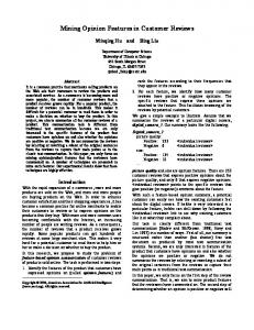
Figure 1.
Proposed framework for feature identification in SOA.
Building up on the work by Luccio et. al. [10, 11], we incorporate Apriori heuristic to present a new algorithm for mining frequent bottom-up subtrees from a set of trees. III. P ROPOSED FRAMEWORK FOR FEATURE IDENTIFICATION IN SOA Figure 1 illustrates the proposed framework for feature identification in SOA which is composed of the following major components: • Scenario Manager is responsible for creating proper Task Clients to exercise the SOA system. A task client performs a sequence of actions to fulfil a specific task. This sequence is referred to as a task scenario. • Trace Collector is responsible for collecting and aggregating distributed execution traces. • Pattern Mining Engine mines execution traces to discover identical subtrees in the collected dynamic call trees from different executions. • Pattern Analyzer analyzes the extracted patterns to distinguish “feature-specific” patterns from “omnipresent” and “noise” patterns. Then, it evaluates them using a set of metrics we defined. In a nutshell, the components of the proposed framework operate through the following steps: i) Scenario Manager configures Task Client to execute a set of carefully selected task scenarios (namely feature-specific scenario set) on the instrumented target web service, such that all task scenarios share a specific feature; each scenario execution generates
one or more service-trace files located in different service platforms; ii) Trace Collector collects the generated execution traces from the service-trace files and aggregates them into a single trace, which represents the whole execution of the Task Client from start to the end; please note that, each trace is represented as a “dynamic method invocation tree” and for simplicity we refer to it as “dynamic call tree”; iii) Pattern Mining Engine first pre-processes the aggregated traces to remove loops in the generated dynamic call trees and then applies a “tree pattern mining” algorithm to the loop-free call trees to identify different tree patterns; iv) Pattern Analyzer analyses the generated patterns to locate core implementation of the shared feature; and v) a number of metrics are applied on the extracted patterns to assess the structural properties of the target SOA-based system. Details of the proposed framework are explained in the following sections. IV. S CENARIO MANAGEMENT The notion of task scenario is borrowed from dynamic analysis domain. In this context, a sequence of user-system interactions to perform a specific task is defined as a taskscenario. Task scenarios are executed on the target system to produce execution traces. For example, in a banking system, the steps for money deposit represent a simple task scenario, and a combination of money deposit and money transfer is a complex task scenario. A feature is a specific functionality of a system and a sequence of features represent a (simple or complex) task scenario. To control the experiments and provide meaningful traces, we generate different sets of task scenarios, such that all task scenarios in a set execute a specific feature of the system. Such a set of task scenarios is called a feature-specific scenario set. In SOA environment, a web service can be composed of one or more service operations. In this context, a specific service operation is considered as a feature of interest, and a feature-specific scenario set share a specific service operation. For example, in Figure 1, operation op1 of service s1 can be considered the feature of interest. In this case, each scenario that uses this operation is a feature-specific scenario and the set of scenarios that all include a call to operation op1 is a feature-specific scenario set. In this example, s1 can represent a banking service and op1 can represent a banking operation such as “entering the amount of money” operation of the “money deposit” bank service. The purpose of a feature-specific scenario set is to execute different parts of the code associated with a feature and generate execution traces accordingly. Previously, most researchers have considered deterministic features in which the behaviour of a feature does not depend on input or state of the system and they always invoke the same set of functions (or methods) from the source code. In practice, most features are non-deterministic and produce different dynamic call trees depending on the state and input
of the system. Assuring coverage in deterministic case is easy as executing a feature once will reveal its underlying code. However, for non-deterministic features, one needs to run enough scenarios to cover different paths in the source code. For this reason we have defined the notion of cases. A case is a certain setting (i.e., a certain predicate on input and system state) imposed to the execution of a feature to make it produce the same results in all executions. For example, scenarios including a call to the service operation withdraw can be grouped into a specific case, if they all conform to the following setting: the account from which the money is withdrawn exists in the bank and the amount to withdraw is less than available funds. To assure proper coverage of the scenarios, we must run a feature in different settings to cover various situations. Scenario Manager component in the proposed framework (Figure 1) is responsible for managing task scenarios and creating their respective Task Clients. A Task Client is the implementation of a task scenario using services in the SOA. Scenario Manager uses WSDL descriptions of services, published in the Service Registry, to generate the proper code for service operations involved in the scenario. V. T RACE COLLECTION AND AGGREGATION An execution trace is a record of events that is generated during a scenario execution on an instrumented software system. During the system operation, we record the method entries and exits as well as their corresponding time stamps. Compared to conventional monolithic systems, collecting trace data from SOA-based systems is challenging [17] for two reasons. 1) Distribution of traces: due to the distributed nature of SOA, execution of a scenario may involve many services and hence it’s corresponding trace may be scattered throughout different service platforms. In this context, the aggregation of traces requires the awareness of what services are involved in an execution which is dynamically determined at run time. 2) Concurrency of events: in a service oriented architecture, services are being exploited by many concurrent users. Therefore, the trace of a service interleaves data related to different users and hence different scenarios. Referring to Figure 1, assume the following situation. We run a scenario including a call to operation op1 of service s1, represented as s1.op1. This results in calling operation op2 of service s2. On the other hand, there is also some unknown client c in the environment which invokes s2.op2 through a call to service s4. In this case, the trace file generated for service s2 contains data related to both clients (i.e., our scenario and the other client’s scenario). Trace Collector component (Figure 1) is responsible for identifying trace data associated with our task scenario from different trace files and aggregate them into a single trace, which represents the execution of our task scenario from start to end. The mechanism we suggest in this paper exploits
three types of causality that are annotated with the recorded trace files: • • •
Time causality: is the before-after relation amongst records, based on their timestamps. Textual causality: is the use of method names as an indicator of a caller-callee relationship. Frequency causality: the fact that the frequency of observing a certain method call in a trace file is related to the frequency of running a certain scenario.
In the aggregation mechanism, we start by processing the trace associated with Task Client, where we search for instances of service operation calls and download the trace files associated with those services. In this step, we start processing the downloaded traces. In this process, we first use time causality between a caller and a callee, and discard data records timed either before the time of service operation call or after returning from that call. Then, we partition the remaining records into a number of data blocks. A data block, is a portion of a trace file which is associated with the execution of a single service operation. We use textual analysis to indicate data blocks. Each data block starts with an “enter” record indicating entrance to a method and ends with an “exit” record indicating exit form the same method. Using textual analysis, we also detect those data blocks which correspond to a different operation from the called operation and discard them. Next, we assign a unique ID to remaining data blocks and add them to a tree called the block execution tree. The block execution tree is proposed in this paper to aid in the process of distributed trace aggregation. It is defined as a directed rooted tree which represents the caller-callee relation among data blocks, where the caller is the block which includes a call to a service operation and the callee is the block associated with that service operation. The block execution tree is built gradually as data blocks are detected in trace files. Root of the tree represents the Task Client and children of the root are the blocks detected in the trace of services that are directly called from Task Client. Figure 2 illustrates an example tree built using this approach. In this figure, (a) shows five trace files associated with services s1 to s5 as well as the trace file associated with Task Client. As you see, the irrelevant trace data is crossed out and the relevant blocks, indicated with ovals, are numbered for unique identification. (b) shows the block execution tree associated with the trace data in (a). In this stage, we remove the remaining irrelevant data blocks from the block execution tree. As mentioned earlier, a large amount of irrelevant trace data have been discarded using time and textual causalities. However, due to concurrency of events in SOA, there is a possibility that the same service operation is called at about the same time by different users. The blocks generated as a result of such incidences cannot be distinguished via time or textual analyses. We
Task Client
s1
s2
1
3
2
4
Root
1
5
1
2
2
6 s4
6
9 1
5 (I)
4
4
6
Root
3
unknown client
8
7
s3
3
8 5
2 (II)
6 3
4
1 (III)
6
5
s5
(a)
(b)
Figure 2. (a) Service trace files partitioned into blocks. (b) Block execution tree associated to (a).
use frequency causality to deal with this issue. In this mechanism, we repeat the execution of Task Client with the same input parameters a certain number of times and count the instances of the questionable data blocks. If the number of instances is more than or equal to the number of runs, the block remains and if not it is deleted from the block execution tree. Respectively, the sub trees starting from deleted blocks are removed. The rationale behind this analysis is that by repeating Task Client, we basically repeat our scenario and respectively each relevant block is repeated in the generated traces. For example in Figure 2, blocks 3 and 4 belong to different scenarios and it is not clear which one is executed after block 1. By applying frequency analysis, we can indicate the relevant block. Resolving all uncertainties leads to a tree where children of a block are blocks associated with different service calls of the same scenario. In this stage, we merge the traces by replacing each service call with it’s corresponding block. A depth first pre-order traversal of the block execution tree indicates in which order the blocks should be visited for this reason. In this traversal, nodes are visited in VLR mode (parent-left child-right child). VI. E XECUTION TRACE MINING In this phase, a set of aggregated execution traces from the previous phase are mined. In the mining process we discover identical subtrees from the tree representation of a set of traces. The proposed subtree mining algorithm is discussed in the following sub sections. A. Background of the mining problem As mentioned in section V, a trace is a sequence of method entry/exit records which correspond to the execution of a scenario which is then represented as a dynamic call tree1 of that scenario. In this work, we model dynamic call trees as rooted labelled ordered trees, where: (1) root of the tree represents the main entry point in the execution of the scenario; (2) nodes represent methods; (3) edges represent method calls; and (4) children of a node are ordered from left to right according to their time of call. 1 Note: different calls to the same function/method are represented by separate tree-nodes, therefore, the result is a “tree” not a “DAG”
Figure 3. An example, illustrating the proposed subtree mining algorithm. Each list entry (e.g., P1{I}) consists of a pointer to the root of a subtree (P1) and the subtree’s support set ({I}). Tree I is represented as string 761052030004. In this example, the minimum support threshold is two.
The problem of mining execution traces in this paper is reduced to mining closed frequent bottom-up subtrees (for short closed frequent subtrees) from a set of trees in a forest. A bottom-up subtree T � of a “rooted labelled ordered tree” T consists of a node from T (as the root of T � ) and all descendants of this node to the leaf nodes; where, the nodes and edges of T � inherit the same properties (i.e., labelling and sibling ordering) from the super tree T . A frequent subtree is a “bottom-up” subtree T � such that the “cardinality” of its super-trees in the forest (namely, “support” of T � ) is greater than or equal to a given “threshold value” (called minimum support). This group of super-trees of T � is called “support set” of T � . A closed frequent subtree is a frequent subtree T � such that all of it’s super-trees T ’s in its support set have smaller support than it has. B. Proposed mining algorithm The proposed subtree mining algorithm in this section is an extension of the bottom-up subtree mining algorithm by Luccio et al. [10, 11]. By considering the minimum support property at early stages of our algorithm, we incorporate the Apriori heuristic to decrease the number of subtrees checked throughout the execution of the algorithm and hence reduce it’s time complexity. In a final step, our algorithm indicates closed patterns and discards non-closed ones. Figure 3 illustrates a 2-dimensional list and four iterations of the proposed algorithm as an example. Steps of the proposed algorithm are as follows. Step 1 - initiate the 2-dimensional list of pointers (Figure 3) that cover all the nodes of the trees in the forest, such that pointers in a row point to nodes in the same tree level (i.e., row L0 of the list contains pointers to all the leaves in the forest), and the number of rows in the list is equal to the maximum tree-height in the forest (4 in the example). Therefore, each entry in the list points to the root
of a bottom-up subtree. In the beginning, we assume that all the subtrees in the rows are “frequent” and mark them accordingly. We also initialize the support set of each subtree with the tree containing it’s root node. Step 2 - iterate over the list, start from row L0 (i.e., the leaves) and continue to row L3; and do the following for each row. a) Identify the support set of each entry in the row and then delete the pointers pointing to a node (i.e., root of a subtree) with at least one infrequent child; according to the Apriori heuristic sub patterns of a frequent pattern must be frequent too. Based on this heuristic, deleting infrequent nodes and their ancestor’s does not change the result of pattern mining. b) Reorganize the remaining pointers in a row (in an ascending order) by comparing the string encoding of the subtrees that they point to. This allows us to identify identical subtrees which become adjacent in a row. A string encoding of a tree is a total ordering of it’s nodes, accompanied by special character 0, which identifies the tree in a unique way. For example, the string encoding of tree I in Figure 3 is 761052030004. This representation can simply be obtained via depth first traversal of tree node. c) Scan the row to update the support sets by aggregating the support set of duplicate subtrees (i.e., same string encoding). For example, as illustrated in Figure 3, in iteration 2, the support set of subtree rooted at 5 is set {I, II}. d) Scan the row to delete each pointer pointing to an infrequent subtree, by counting it’s support set and comparing it to the minimum support threshold. Mark the corresponding nodes as “infrequent”. Step 3 - scan the 2-dimensional list from last row (i.e., the root nodes in L3) to the first (i.e., the leaves in L0) to delete subtrees with the same support set as their children. For each pointer at a higher row, we delete it’s children located at lower rows of the list, if the parent and child have same support set. The remaining pointers in the 2-dimensional list indicate closed frequent bottom-up subtrees of a forest. Having a linked list implementation of the 2-dimensional list, where the operations add and delete take o(1), the time complexity of the algorithm in the worst case is o(m.n.log r + n.s) , where m is the number of nodes in the largest tree in the forest, n is the number of all nodes in the forest, r is the size of longest row in the list, and s is the number of trees in the forest, for the following reasons. Steps 1, 2-a, 2-c, and 2-d each require a single pass over the nodes of the forest and thus take the total of o(n); Step 2-b takes the total of o(m.n.log r) where the comparison takes the maximum of o(m) and thus sort takes the maximum of o(n.m.log r); Step 3 is done in a single pass over the nodes of the forest where the comparison of support sets takes o(s). VII. PATTERN ANALYSIS The extracted patterns in the previous step, illustrate the similarities that exists in a set of feature-specific task scenarios and thus convey knowledge about the shared feature. In
Feature 1
P1 P2 P3 P4 P5
Feature 2
Figure 4. Traces associated with two feature-specific scenario sets and their corresponding patterns. For simplicity we have serialized each trace based on the time of method entries.
this stage, we analyze the extracted patterns to indicate their relevancy to the feature by distinguishing feature-specific, omni-present, and noise patterns. Then, we define a number of metrics to assess structural properties of the target SOAbased system by analysing the feature-specific patterns. A. Identifying feature-specific patterns There are three kinds of patterns detected as the result of mining the execution traces of a set of feature-specific scenarios. Feature-specific patterns are specific to the shared feature. In other words, a feature-specific pattern indicates a path in the source code of the system that implements part of the core logic of the feature. Omnipresent patterns are common among all scenario sets. They are comprised of methods such as class initializers, SOAP message transmission procedures, that help implementation of the feature but not specific to a single feature. Noise patterns are random similarities among scenarios, where the similarities are not the result of feature execution but some other shared operation. To distinguish pattern types, we create a trace-pattern matrix M where each row of the matrix represents a trace and each column represents a pattern. A check mark in element mij indicates that pattern j exists in trace i. A sample trace-pattern matrix is illustrated in Figure 5. Detecting omni-present and noise patterns is straightforward. A pattern, such as p1, that appears in all featurespecific traces of all features is omni-present. Also, a pattern that is neither feature-specific, nor omnipresent, is noise. Detecting feature-specific patterns is more challenging. In this paper, we consider both deterministic and nondeterministic features. A deterministic feature always generates the same dynamic call tree. In this case, a featurespecific pattern is one that appears in all the traces of a feature-specific scenario set and is not omni-present. For example, in Figure 4, (m3, m6) represents a feature-specific pattern for deterministic feature 1. A non-deterministic feature generates distinct patterns in different executions. Considering Figure 4, (m4, m10) and (m2, m9) represent feature-specific patterns for non-deterministic feature 2. To indicate feature-specific patterns, we first identify candidate sets of feature-specific patterns such that: 1) none of the patterns in a candidate set is omni-present; 2) each feature-specific trace contains exactly one of the patterns
Figure 5.
The trace-pattern matrix associated with Figure 4.
in a candidate set. For example, in Figure 5, {p4, p5} is a candidate feature-specific pattern set for feature 2. In this stage, we may come up with one or more candidate sets. We apply text-based analysis to identify which candidate set is really feature-specific. In this analysis, we compare feature name to the name of methods in the patterns of each candidate set. If an examined pattern does not have any instances of the feature name or the derivatives of the feature name, it will be considered noise and its corresponding candidate set will be omitted. To justify this approach, consider the fact that each feature-specific scenario executes the feature exactly once. Therefore, each trace will have exactly one incident of any pattern that the shared feature generates. For example, referring to Figure 5, assume that patterns p4 and p5 are feature-specific patterns for feature 2. This means that in any execution of feature 2 we see either p4 or p5 exclusively. Therefore, each feature-specific trace ti is expected to have a check mark for either p4 or p5. B. Structural analysis of SOA In this step, we define two metrics to evaluate the structural merit of a SOA-based system using it’s execution traces. Service Utilization enables assessment of a service, based on how it’s operations utilize other SOA services. Call Frequency indicates communication overhead of a service. In both metrics, we assume the feature under study is a service operation. Service Utilization Service utilization indicates the average service usage in the implementation of a specific service operation and is formally defined as follow. • Let Sop = ∪pi ∈Pop Spi be the set of services contributing in the execution of operation op. • Let Mop = ∪pi ∈Pop Mpi be the set of methods contributing in the execution of operation op. • Let Msi = {m1 , m2 , .., mo } be the set of all methods in service si . • The service utilization for operation op, namely SU (op) is defined as: � |M i ∩Mop | SU (op) = |S1op | ∗ si ∈Sop s|M si | Service utilization uses feature specific patterns to obtain the average method coverage of an operation op
with respect to the web services that together implement that operation. Greater service utilization indicates more efficient use of the involving services. Using a portion of service capabilities, in general, is not preferable, since: 1) we are paying for the whole service and using part of it is not economical; 2) more maintenance effort is needed for a bigger service even though we are not using all of it. Also, less efficient use of services in general implies that more services are needed for the same amount of work in an operation which makes that operation more costly. Therefore, a service with higher SU is generally a better choice for selection. Call Frequency Call Frequency measures the average number of calls to remote services in the execution of a specific service operation and is formally defined as: • Let Pop = {p1 , p2 , ..., pl } be the set of feature-specific patterns for operation op. • Let Spi = {s1 , s2 , ..., sm } be the set of services contributing in the execution of pattern pi . • Let OPsi ,pj = {op1 , op2 , .., opn } be the set of operations that are defined in the interface of service si and called in pattern pj . • The Call Frequency of pattern pk , namely CF (pk ) is defined as follow. CF (pk ) = �|Spk | �|OPsi ,pk | number of calls to si .opj i=1 j=1 • We define the Call Frequency of operation op, namely CFavg (op), as: �l CF (pi ) CFavg (op) = i=1 |Pop | In general, more remote service calls in the implementation of an operation implies more overhead. It: 1) increases network message traffic; 2) increases the time required for the operation; 3) makes the operation more unreliable as it is dependant to remote services. Therefore, a service with less CF is a better choice for selection. VIII. C ASE STUDY In this section, using two examples SOA-based systems, we illustrate how the proposed framework can be incorporated to identify distributed features in SOA-based systems. We also discuss how the proposed metrics can facilitate the comparison of services. A. Prototype SOA-based systems In this study, we implemented two SOA-based systems which provide banking operations, such as opening an account, depositing money to an account, transferring money between accounts, etc. The prototyped systems are illustrated in Figure 6. Each system in this figure consists of a number of services, represented as circles, which collaborate to
openChqAccount withdraw email_money ...
open
Mybank Account Access Service
balance deposit withdraw open
evaluate _risk
balance deposit
Credit Check Service
Chequing Account Service
open openChqAccount email_money withdraw ...
LineOfCredit Account Service
Somebank Interface Service
withdraw
withdraw
deposite
doWithdraw
check_ liabilities
open Bank2 chequing Account Service
balance
Credit Check Service
chq Account Service
doDeposite
(a)
Figure 6.
Bank1 Chequing Account Service
Bank 2
openAccnt getBalance
deposit withdraw
Bank 1
deposit withdraw balance ...
Banking Service
balance
(b)
(a) and (b) illustrate two service oriented banking examples used as a case study in this work.
provide the required operations. Arrows between circles indicate the service invocations. For example Mybank Account Access Service uses operations from Chequeing Account Service, LineOfCredit Account Service and Credit Check Service during the execution of its operations. We have used Java platform Enterprise Edition (Java EE) to implement our target systems. The services in both systems execute on Apache Tomcat 5.5 and are instrumented using TPTP probekit [1]. TPTP probekit allows collection of run time data about a program at various points in the execution such as method entry, method exit, class loading, etc. It provides us with means to write fragments of Java code that can be invoked at the specified points. The generated traces in this study record entry and exit to/from methods during the execution, and their time stamps. B. Creating scenario sets To extract feature-specific code, we execute proper task scenarios on target systems and analyze the resulting traces. Figure 7 illustrates some of the scenarios used in this study. Each scenario is comprised of a sequence of operation calls. For example, in scenario W 9 we first open a chequeing account for John with $500 funds; this operation returns John’s account number. Then, we withdraw $500 from John’s account. The scenarios are categorized into two feature-specific sets. In (1) the operation under study is withdraw which is shared in all scenarios of this set and in (2) email-money is the operation under study. The scenarios in each feature-specific set are partitioned into a number of cases, where each case examines a service operation in a specific context. For example, scenarios W 9 and W 10 examine operation withdraw in the case that the account to be withdrawn from exists and the amount to withdraw is less than or equal available funds. C. Execution trace extraction and aggregation After indicating the scenario sets, the proposed framework executes each scenario on target systems and aggregates the generated trace files. Figure 8 illustrates the block execution tree related to the execution of scenario EM 2 (Email
deposit (accountNumber, funds) email_money (FROMbankName, FROMaccountNumber, TObankName, TOaccountNumber, funds) openCHQ (Name, initialFunds) withdraw (accountNumber, funds)
Figure 7. Service.
Part of the scenarios used to examine Mybank Account Access
Money) on the first target system, illustrated in Figure 6 (a). To represent a real world conditions, we execute other random scenarios in parallel with the execution of EM 2. Therefore, the generated traces contain the execution records of the other scenarios as well. In this stage, Trace Collector applies frequency analysis to remove irrelevant data blocks. For example, in Figure 8, blocks 1 and 2 belong to different scenarios. We ran scenario EM 2 5 times and counted 5 instances of block 1 and 2 instances of block 2. Therefore, we marked block 2 as being irrelevant to scenario EM 2 and deleted it from the block execution tree in Figure 8 (b). Applying depth first traversal on the resulting block execution tree, the ordering of the blocks for aggregation is 1, 4, 3, 5, 6, 7. In this stage Trace Collector merges the blocks to create the start-to-end trace of
Mybank Account Access Service
Client for scenario EM2 .........
open (1)
.........
open ......... (4) ......... ......... withdraw ......... (5) .........
Call Mb_Chq.open
......... open ......... ......... (2)
Call Mybank.open
......... .........
(Root)
Chequing Account Service
Call Mybank.email_ money
.........
email_ money
Call Mb_Chq.withdraw Call Somebank.deposit
(3) deposit
(6)
(a)
.........
.........
Call Sb_Chq.deposit
deposit
.........
(7)
.........
Chq Account Service
Somebank Interface Service Root
1
Root
2 5
4 (b)
3
1
3 6
4
7
5 (c)
6 7
Figure 8. (a) Trace files and blocks for scenario EM2. (b) The associated block execution tree before frequent analysis (c) The associated block execution tree after frequency analysis.
scenario EM 2. It starts from the root node and recursively replaces every instance of a remote service call with the respective service trace block. In this step, Pattern Mining Engine mines the dynamic call tree representation of the each feature-specific set of traces. Table I indicates statistics about the results of execution pattern mining and analysis for operation withdraw for both target systems in Figure 6. Using the trace-pattern matrix associated with the scenarios we discussed in Section VII (Figure 5), we recognized three feature-specific patterns for operation withdraw in the first target system and four feature-specific patterns for withdraw in the second. Figure 9, illustrates the featurespecific patterns extracted from the execution of withdraw on the first system. For simplicity we have serialized each pattern by noting only the sequence of method entries. Each pattern in this figure is a sequence of method invocations separated with “,”. Each method is specified as packageName/className.methodName. For example, in pattern 3, com/ibm/chqaccntimplstub. represents the invocation of method of class chqaccntimplstub from package com/ibm. Considering the feature-specific patterns, we have computed Service Utilization and Call Frequency metrics as illustrated in tables II and III.
Figure 6 (a) Figure 6 (b)
Number of Services 2 3
pattern 2: mybank/accessinterfacestub.withdraw, mybank/ accessinterfacestub.optimizecontent, mybank/accessinterfacestub.toenvelope, mybank/accessinterface., mybank/accessinterface.withdraw, mybank/ accessinterface.accountservicefor, mybank/ accessinterfacestub.getenvelopenamespaces, mybank/ accessinterfacestub.fromom pattern 3: mybank/accessinterfacestub.withdraw, mybank/ accessinterfacestub.optimizecontent, mybank/accessinterfacestub.toenvelope, mybank/accessinterface., mybank/accessinterface.withdraw, mybank/ accessinterface.accountservicefor, com/ibm/chqaccntimplstub., com/ibm/ chqaccntimplstub., com/ibm/chqaccntimplstub., com/ibm/ chqaccntimplstub., com/ibm/chqaccntimplstub., com/ibm/ chqaccntimplstub., com/ibm/chqaccntimplstub.populateaxisservice, com/ ibm/chqaccntimplstub.getuniquesuffix, com/ibm/chqaccntimplstub.populatefaults, com/ibm/chqaccntimplstub.withdraw, com/ibm/ chqaccntimplstub.optimizecontent, com/ibm/chqaccntimplstub.toenvelope, com/ ibm/chqaccntimpl., com/ibm/chqaccntimpl.withdraw, com/ibm/ chqaccntimpl.ischequing, com/ibm/chqaccntimpl.validaccount, mybank/ accessinterfacestub.getenvelopenamespaces, mybank/ accessinterfacestub.fromom
Figure 9. Feature-specific patterns for operation withdraw in first target system in Figure 6 (a).
E. Discussion
D. Pattern mining and analysis
Architecture
pattern 1: mybank/accessinterfacestub.withdraw, mybank/ accessinterfacestub.optimizecontent, mybank/accessinterfacestub.toenvelope, mybank/accessinterface., mybank/accessinterface.withdraw, mybank/ accessinterface.accountservicefor, com/ibm/chqaccntimplstub., com/ibm/ chqaccntimplstub., com/ibm/chqaccntimplstub., com/ibm/ chqaccntimplstub., com/ibm/chqaccntimplstub.populateaxisservice, com/ ibm/chqaccntimplstub.getuniquesuffix, com/ibm/chqaccntimplstub.populatefaults, com/ibm/chqaccntimplstub.withdraw, com/ibm/ chqaccntimplstub.optimizecontent, com/ibm/chqaccntimplstub.toenvelope, com/ ibm/chqaccntimpl., com/ibm/chqaccntimpl.withdraw, com/ibm/ chqaccntimpl.ischequing, com/ibm/chqaccntimpl.validaccount, com/ibm/ chqaccntimpl.balance, com/ibm/chqaccntimpl.ischequing, com/ibm/ chqaccntimplstub.getenvelopenamespaces, com/ibm/chqaccntimplstub.fromom, mybank/accessinterfacestub.getenvelopenamespaces, mybank/ accessinterfacestub.fromom
Service Utilization 0.41 0.49
Table II S ERVICE U TILIZATION OF OPERATION withdraw FROM Mybank Account Access Service AND Banking Service IN TARGET SYSTEMS IN F IGURE 6.
The results produced using our framework assist in the maintenance and structural analysis of a SOA-based system. Feature-specific patterns reveal part of the static call graph of a system which implements the core logic of a certain functionality. This helps maintainers localize a “failure scenario” by decomposing it to the features it involves, and examining the patterns associated with each feature. Partitioning patterns to Feature-specific and omnipresent helps distinguishing the core logic of a feature from the technology related code such as the methods required for Web service SOAP messaging. This helps maintainers upgrade the system with respect to new technologies. The proposed Service Utilization and Call Frequency metrics assist in service comparison and selection. For example, greater Service Utilization in the second target system indicates that Banking Service uses other services more efficiently in the execution of operation withdraw as opposed to Mybank Account Access Service and thus it is more preferable. Also, greater Call Frequency in the second target system shows that Banking Service generates more remote communications in the execution of operation withdraw as opposed to Mybank Account Access Service. In this sense, the second service is less preferable. Depending on the application, a service requester can indicate an order of importance between the provided metrics. Based on this ordering, a service selection engine can suggest the most suitable service for the requester. For example, for a requester who is more concerned about communication costs
Architecture
Number of Scenarios
Number of Cases
Number of Patterns
Average Trace Size
Average Pattern Size
Figure 6 (a) Figure 6 (b)
12 12
4 4
26 22
51 55
23 25
Number of Feature-specific Patterns 3 4
Average Feature-specific Pattern Size 19 22
Table I T HE RESULT OF EXECUTION PATTERN MINING AND ANALYSIS FOR OPERATION withdraw FOR TARGET SYSTEMS IN F IGURE 6. Architecture
Feature-specific Pattern
Figure 6 (a)
p1 p2 p3 p1 p2 p3 p4
Figure 6 (b)
Total Frequency of Remote Calls 2 1 2 1 2 2 3
Number of Feature-specific Patterns 3
Call Frequency
4
2
1.7
Table III C ALL F REQUENCY OF OPERATION withdraw FROM Mybank Account Access Service AND Banking Service IN TARGET SYSTEMS IN F IGURE 6.
than efficiency of service usage, the first system seems to be a better choice. IX. C ONCLUSION AND FUTURE WORK The growing numbers of service based applications, service providers, and business enterprises that use these services impose new challenges on software maintenance community who must deal with these systems. To address this issue, in this paper we proposed a novel framework for identifying features from distributed traces in the context of service oriented architecture. We presented mechanisms for: i) collecting and aggregating distributed traces of services using three causality techniques; ii) mining feature-specific and omni-present patterns for non-deterministic features; and iii) assessed the structural merit of a SOA-based system using the pattern mining results. We also discussed, using a case study, how the results can help system maintenance and service comparison for the purpose of service selection. As the next step, we plan to extend our framework to localize a software failure by storing the patterns associated with our scenarios in a database and comparing the trace of a failure scenario with the available patterns. R EFERENCES [1] Eclipse Test and Performance Tools Platform Project. http://eclipse.org/tptp/. [2] A. Marcus et al. An Information Retrieval Approach to Concept Location in Source Code. In Proc. IEEE Working Conf. on Reverse Engineering, pages 214–223, 2004. [3] R. Agrawal and R. Srikant. Fast algorithms for mining association rules. In Proc. Intl. Conf. on Very Large Data Bases, pages 487–499, 1994. [4] G. Antoniol and Y. Gueheneuc. Feature Identification: A Novel Approach and a Case Study. In Proc. IEEE Intl. Conf. on Software Maintenance, pages 357–366, 2005. [5] K. Chen and V. Rajlich. Case Study of Feature Location using Dependence Graph. In Proc. Intl. Workshop on Program Comprehension, pages 241–249, 2000. [6] D. Edwards, S. Simmons, and N. Wilde. An Approach to Feature Location in Distributed Systems. J. of Systems and Software, 79(1):57– 68, 2006. [7] T. Eisenbarth, R. Koschke, and D. Simon. Derivation of Feature Component Maps by Means of Concept Analysis. In Proc. European Conf. on Software Maintenance and Reengineering, pages 176–179, 2001.
[8] T. Eisenbarth, R. Koschke, and D. Simon. Locating Features in Source Code. IEEE Transactions on Software Engineering, 29(3):210–224, 2003. [9] D. Eng. Combining static and dynamic data in code visualization. In Proc. ACM SIGPLANSIGSOFT Workshop on Program Analysis for Software Tools and Engineering, pages 43–50, 2002. [10] F. Luccio et al. Exact Rooted Subtree Matching in Sublinear Time. Technical Report TR-01-14, Universita Di Pisa, 2001. [11] F. Luccio et al. Bottom-up Subtree Isomorphism for Unordered Labeled Trees. Technical Report TR-04-13, Universita Di Pisa, 2004. [12] R. Fonseca. Improving Visibility of Distributed Systems through Execution Tracing. PhD thesis, School of Electrical Engineering & Computer Sciences, University of California Berkeley, 2008. [13] J. Coffey et al. Locating Software Features in a SOA Composite Application. Technical Report S2ERC-TR-304, 2010. [14] J. Moe and D. A. Carr. Using Execution Trace Data to Improve Distribute Systems. Software-Practice & Experience, 32(9):889–906, 2002. [15] M. Salah et al. Towards Employing UseCases and Dynamic Analysis to Comprehend Mozilla. In Proc. IEEE Intl. Conf. on Software Maintenance, pages 639–642, 2005. [16] N. Wilde et al. A Comparison of Methods for Locating Features in Legacy Software. J. of Systems and Software, 65:105–114, 2003. [17] N. Wilde, et al. Understanding Features in SOA: Some Experiences from Distributed Systems. In Proc. Intl. Workshop on Systems Development in SOA, pages 59–62, 2008. [18] P. Bahl, et al. Towards Highly Reliable Enterprise Network Services via Inference of Multi-level Dependencies. SIGCOMM Computer Communication Review, 37(4):13–24, 2007. [19] P. Reynolds, et al. Wap5: Black-Box Performance Debugging for Wide-area Systems. In Proc. Intl. Conf. on World Wide Web, pages 347–356, 2006. [20] K. Sartipi and H. Safyallah. Dynamic Knowledge Extraction from Software Systems using Sequential Pattern Mining. Intl. J. of Software Engineering and Knowledge Engineering, 20(5), 2010. 22 pages. In press. [21] T. Savage, M. Revelle, and D. Poshyvanyk. FLAT3: Feature Location and Textual Tracing Tool. In Proc. Intl. Conf. on Software Engineering, pages 255–258, 2010. [22] S. E. Sim, C. L. A. Clarke, and R. C. Holt. Archetypal Source Code Searches: A Survey of Software Developers and Maintainers. In Proc. Intl. Workshop on Program Comprehension, pages 180–187, 1998. [23] N. Wilde and M. Scully. Software Recnnaissance: Mapping Program Features to Code. J. of Software Maintenance: Research and Practice, 7:49 – 62, 1995. [24] X. Chen, et al. Automating Network Application Dependency Discovery: Experiences, Limitations, and New Solutions. In Proc. USENIX Symposium on Operating Systems Design and Implementation, pages 117–130, 2008. [25] Y. Chi et al. Frequent Subtree Mining - An Overview. Fundamenta Informaticae, 66(1-2/2005):161–198, 2005.