ON-OFF Temperature Control System Using Microprocessor ... controlling the
operation of heater using microprocessor. .... D. Working of Microprocessor 8085.
Session: Poster
National Conference on Computing, Communication and Control (CCC-09)
ON-OFF Temperature Control System Using Microprocessor Shefali Saxena#1, Swati Talesara#2,Sachin Mehta#3 #
Electronics & Communication Department, Geetanjali Institute of Technical Studies Udaipur, Rajasthan, India
[email protected] [email protected] 3
[email protected]
1 2
Abstract— This paper includes the On-Off Control System controlling the operation of heater using microprocessor. It is a closed-loop control system. An on-off controller is the simplest form of temperature control device. An on/off controller will switch the output only when the temperature crosses the set point. For heating control, the output is on when the temperature is below the set point, and off above the set point.The paper deals with control system including strategies, types and requirements of control system. Block diagram of On-Off Temperature Controller using Microprocessor with explanation of Working of whole circuit has been included .The observations of experiment on actual circuit have been reported. Keywords- Control, comparator, temperature, microprocessor, digital.
I. INTRODUCTION During the last fifty years, control systems in processes have been gradually evolved on an analytical footing and today the range in the control equipment for any kind of process is commendable. The major part in process controllers the plant or the process itself. For adequate control, knowledge of the plant characteristics, both theoretical and experimental is therefore necessary. On-Off Control System is used in many common situations, such as air-coolers, water reservoirs, batch annealing furnaces, etc. In control theory, a controller is a device which monitors and affects the operational conditions of a given dynamical system. The operational conditions are typically referred to as output variables of the system which can be affected by adjusting certain input variables.
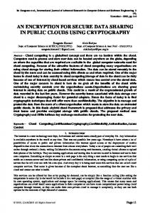
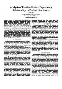
temperature is near the set-point. The fluctuations in temperature shown on the graph are significantly larger than the hysteresis, as can be confirmed with the interactive simulation, due to the significant heat capacity of the heating element. A process control system basically consists of two parts: 1. The process 2. The control equipment. The control equipment broadly consists of: 1. Measurement system 2. Comparator 3. Controller 4. Actuator
Fig. 1 Block diagram of basic control loop
II. PRACTICAL CIRCUIT & WORKING
A. On-Off Control This is the simplest form of control, used by almost all domestic thermostats. When the oven is cooler than the setpoint temperature the heater is turned on at maximum power, M, and once the oven is hotter than the set-point temperature the heater is switched off completely. The turn-on and turn-off temperatures are deliberately made to differ by a small amount, known as the hysteresis H, to prevent noise from switching the heater rapidly and unnecessarily when the
132
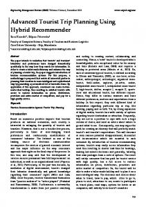
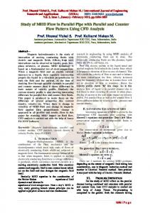
Fig. 2 Block Diagram of ON-OFF control system Fig. 3 Circuit Diagram of ON-OFF control system
Session: Poster
National Conference on Computing, Communication and Control (CCC-09)
On-Off Control System using microprocessor is a control system operating a heater in such a way that heater will be automatically turned OFF above the specified temperature of water (here it is 40°C) and turned ON below the specified temperature of water. Microprocessor has been used for controlling the operation of heater according to the input voltage. Input voltage of microprocessor is according to the water temperature. Thermistor has been used here as a sensor and transducer for converting temperature into voltage. In microprocessor comparator program has been fed with a reference value with which input voltage is compared. If input voltage is less, the DAC output is low and relay circuit is in OFF condition. If input voltage is high, the DAC output is high and relay circuit is in ON condition which operates the heater. Hence On-Off controlling of heater has been done according to temperature.
2)
Op-amp has been used in non-inverting configuration with a gain of 51. 3) Gain of non-inverting op-amp is given by, A = 1 + (R f / R i ) Where, R f is the feedback resistance, 1kohm R i is the input resistance, 20ohm A = 1 + (1000/20) A = 51 4) Voltage observed at the output of op-amp is in volts. C. Working of ADC 0809 1) Since the voltage observed at the output of op-amp is an analog value and microprocessor operates only on digital values, therefore analog voltage has been converted into equivalent digital voltage using ADC.
A. Working of Thermistor
2) ADC uses the principle of successive approximation technique for the conversion process. D. Working of Microprocessor 8085 1) Microprocessor performs the operation of comparison of digital output of ADC with reference value for deciding the output of microprocessor which will further decide the state of transistor (either cut-off or saturation).
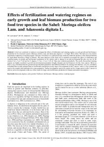
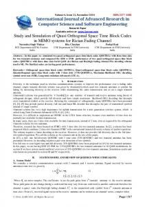
Fig. 4 Circuit for measurement of voltage across thermistor
2) If the digital output of ADC is less than the reference value then the output of microprocessor will be low level digital signal (i.e. 00H).
1) Thermistor, as the name suggests, sense the temperature of water. According to the temperature of water, resistance of thermistor varies.
3) If the digital output of ADC is greater than the reference value then the output of microprocessor will be high level digital signal (i.e. FFH).
2) Here NTC (Negative Temperature Coefficient) thermistor has been used whose resistance is 8ohm at room temperature. 3) It has been observed as temperature of water increases, resistance of thermistor decreases and therefore voltage drop across thermistor decreases. 4) Thus thermistor has been used here for converting temperature (a non-electrical quantity) into voltage (an electrical quantity). 5) Output voltage measured across two terminals of thermistors using resistive network is in millivolts (as shown below). B. Working of Operational Amplifier 1) The voltage observed at the two terminals of the thermistor in the above circuit is in millivolts, therefore an op-amp has been used as an amplifier to amplify or increase the voltage level.
E. Working of DAC 1) Since the output of microprocessor will be a digital signal and transistor operates on analog signal, therefore a DAC is required for conversion of digital signal to analog signal. 2) Equivalent DAC output for high level digital output signal of microprocessor (i.e. FFH) is +2.5V theoretically and +1.9V practically which is enough for driving the transistor in ON state (transistor will operate in saturation region). 3) Equivalent DAC output for low level digital output signal of microprocessor (i.e. 00H) is -2.5V theoretically as well as practically which is enough for driving the transistor in OFF state(transistor will operate in cut-off region).
133
Session: Poster
National Conference on Computing, Communication and Control (CCC-09)
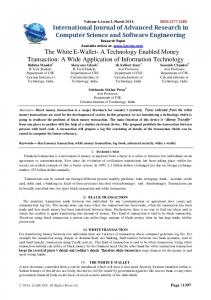
F. Flow Chart Representing Complete control Process
In this case voltage across the inductor will be 12V and current flowing in the circuit can be determined using equation (3) as I = Vo/R (1-exp. (-R t /L)) Here, R -> Resistance of inductor coil = 200ohm Vo->Voltage across inductor in case 1 = 12V L->Inductance of coil = 569.2mH At t = 0.5sec I = 12/200(1-exp.(200*.5*1000/569.2)) I = 0.06A 2) Case2: i. When the DAC output will be low i.e. -2.5V, the transistor will turn OFF and voltage at collectoremitter junction, V ce = V cc = 12V and diode gets forward biased so switch S1 will be close and switch S2 will be open. Relay will act as a open switch and the heater will be turned OFF. ii.
Fig. 5 Flow chart representing the complete process
III. OBSERVATIONS A. Driving Transistor with DAC Output
Fig.8 Equivalent circuit when S1 is ON and S2 is OFF
In this case inductor will start discharging through diode with current direction same and voltage polarity opposite to that previous one. Output of this Relay Driver circuit is used to ON-OFF the heater according to the reference temperature. B.
Fig.6 Equivalent circuit for relay driver design circuit
TABLE I VARIOUS EXPERIMENTAL RESULTS
1) Case1: i. When the DAC output will be high i.e. 1.9V, the transistor will turn ON and voltage at collectoremitter junction, Vce(sat)=.7V and diode gets reverse biased so switch S1 will be open and switch S2 will be close. Relay will act as a close switch and the heater will be turned ON. ii.
S. No.
Amplifier Output (V)
Equivalent Digital O/P of A/D Converter
Temperature (°C)
Equivalent Voltage across Thermistor (mV)
1.
95
17.3
0.80
10
2. 3. 4. 5. 6.
75 60 50 40 32
24.5 32.7 42.2 53.9 67.0
1.18 1.60 2.08 2.66 3.33
3C 51 69 86 A8
IV. IDENTIFICATION(STABILITY) OF THE SYSTEM
Fig.7 Equivalent circuit when S1 is OFF and S2 is ON
134
Session: Poster
National Conference on Computing, Communication and Control (CCC-09)
System identification is based on the step input response of the open loop system. To identify the system it is necessary to check the frequency stability of the system. Frequency stability of the system is defined as the range of frequencies over which the system works efficiently and accurately. It is obtained by observing the output of the system at various frequencies and checking whether it is similar to the desired output or not.
3) Observation 3: Fig.9 Circuit Diagram of open loop system for identification of the circuit
4) Observation 4: A. Procedure 1) A step input was applied to the voltage divider network supply by using function generator. 2) The frequency of the step input signal is changed step by step and output of open loop system is observed at various input signal frequencies.
V. CONCLUSION Thus the on-off control system works for frequency upto 5.95Hz. Upto this frequency output is stable and depending upon the temperature value device is either on or off. This on/off controller will switch the output only when the temperature crosses the set point.
B. Observations 1) Observation 1: ACKNOWLEDGMENT The authors would like to express their gratitude to Mr. Pradeep Chhawchharia, who has the attitude and the substance of a genius. He continually and convincingly conveyed a spirit of adventure in regard to project, and an excitement in regard to his teaching and providing lab facilities . REFERENCES [1]
2) Observation 2:
[2]
[3] [4] [5]
135
Szatkowski, A.; Pruehsner, W.; Enderle, J.D., “Water temperature control system”, Bioengineering Conference, 1999. Proceedings of the IEEE 25th Annual Northeast Volume , Issue , 8-9 Apr 1999 Page(s):39 – 40 Peng Yang; Hongyu Zhao; Ying Zhou; Zhiwei Liu, “Study of Immune PID-PI Controller for FG-3000 Temperature Control System”, Integration Technology, 2007. ICIT apos;07. IEEE International Conference on Volume , Issue , 20-24 March 2007 Page(s):343 – 347 Ramesh Gaonkar, “ Microprocessor Architecture, programming, and applications with the 8085, Fifth edition D Patranabis, “ Principals of Process Control”, Second Edition National Semiconductor - Data Sheet for ADC0809, Intel 8085 microprocessor datasheet