Image reconstruction algorithms for microtomography. Andrei V. Bronnikov.
Bronnikov Algorithms, The Netherlands. Page 2. BronnikovAlgorithms. •
Introduction.
Image reconstruction algorithms for microtomography Andrei V. Bronnikov
Bronnikov Algorithms, The Netherlands
Contents • • • • •
Introduction Fundamentals of the algorithms State-of-the-art in 3D image reconstruction Phase-contrast image reconstruction Summary
BronnikovAlgorithms
Microtomography systems Desktop systems Image Intensifier Object
Camera control
PC
X-Ray tube
Motor control Camera Manipulation system
Rail system
NDT systems
Small animal CT
Nano x-ray microscopy
Dental CBCT
Synchrotron setup
BronnikovAlgorithms
Micro CT images
Stampanoni et al Sterling et al
Dental CBCT
BronnikovAlgorithms
Problems • Object preparation, fixation, irradiation, etc • Polychromatic source, miscalibrations, etc • Small object size: insufficient absorption contrast • Limited field-of-view, limited data, incomplete geometry • Large amount of digital data
BronnikovAlgorithms
Solutions • Region-of-interest reconstruction • Fully 3D cone-beam scanning and reconstruction • The use of phase contrast • Software/hardware acceleration
BronnikovAlgorithms
Geometry
Parallel beam Synchrotron
The source is far away from the object
Cone beam Microfocus tube, microscopy
The source is close to the object: - Increased flux - Magnification - Fully 3D
BronnikovAlgorithms
`
I nverse problem
Projection data: g , s
f dl Line ( , s )
s
Radon transform
Af
g
To find f from g ?
Object: f BronnikovAlgorithms
`
Backprojection Integration of the projection data over the whole range of * A g
1
g d 0
BronnikovAlgorithms
Algorithms: classification Radon transform • Fourier algorithm • Filtered backprojection (FBP) • Backprojection and filtering (BPF) • Iterative
Af
f
Imaging equation
g *
1
*
*
A A
A AA
*
A g 1
BPF
g
FBP
1
Fn Fn 1 g
Fourier
BronnikovAlgorithms
Parallel-beam geometry (Synchrotron)
BronnikovAlgorithms
Fourier slice theorem
BronnikovAlgorithms
I mage reconstruction w ith NFFT
f
1
F2 F1 g
Interpolation from the polar grid to the Cartesian is required
Linogram (“pseudo-polar”) grid
Nonequispaced Fast Fourier transform (NFFT) can be used Potts et al, 2001 BronnikovAlgorithms
FBP and BPF algorithms
f *
F2 A A
1
*
A A 1
2
*
A g 2
*
1
*
A AA
*
F1 AA
g
1
“ramp filter”
f
1
F2
1
2
2
g d 0
f
1
F1 1
g d
0
BronnikovAlgorithms
FBP algorithm
1D Filtering
Backprojection
f
q g d 0
BronnikovAlgorithms
Local ( “Lambda”) tomography F1 1
s
g
gˆ
H
s
g
Local operator
A* H
f
f
s
g
*
A
s
g
Hilbert transform is non-local:
Hg ( s )
1
g (t ) dt s t BronnikovAlgorithms
Cone-beam geometry (Microfocus x-ray tube)
BronnikovAlgorithms
Feldkamp algorithm w ith a circular orbit Feldkamp, Davis, Kress, 1984
Filtering
Z
X
Backprojection
f
q g d 0 BronnikovAlgorithms
Kirillov-Tuy condition detector Exact 3D reconstruction is possible if every plane through the object intersects the source trajectory at least once u
s a( )
f
g (a( ), u )
f (a( ) su )ds 0
x-ray source trajectory; parametrized as a( )
BronnikovAlgorithms
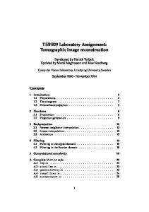
Circular source orbit: artifacts Slices of 3D reconstruction of a phantom (cone angle 30 deg):
Bronnikov 1995, 2000
BronnikovAlgorithms
ROI reconstruction
Two-step data acquisition
Position 1
Position 2
Source ROI Sample
Sample
Detector
BronnikovAlgorithms
Non-planar source orbits Non-planar 3D reconstructions of a phantom:
- two
orthogonal circles - two circles and line - helix (most feasible mechanically) - saddle
Non-planar orbits satisfy the Kirillov-Tuy condition, but special reconstruction algorithms are required BronnikovAlgorithms
Katsevich algorithm for a non-planar source orbit Katsevich, 2002
f a( 2)
PI-line (“segment”, “chord”) between a( 1) and a( 2):
a
g
1. Differentiation of data 2. Hilbert transform along the filtration lines inside the Tam-Danielson window 3. Backprojection
a( 1)
Helix:
1 * A H 2
h R cos , R sin , 2
2
1=2
T
BronnikovAlgorithms
BPF algorithms for ROI reconstruction f
1 H A* 2
g
1. Differentiation of data 2. Backprojection onto the PI chord (locality!) 3. Hilbert transform along the PI chord
Using that f has the finite support and
HHg
g
a( ) Zou, Pan, Sidky, 2005 derived:
f
1 H 2
1 * A ,a1 a 2
g
BronnikovAlgorithms
Ultra-fast implementation • Graphic card (GPU) • CPU Reconstruction of a 512x512x512 image from 360 projections:
CPU (~2 GHz) :
Single
Dual core
Quad core
Twin quad-core
Time :
~80 sec
~40 sec
~20 sec
~10 sec
Reconstruction of a 1024x1024x1024 image from 800 projections:
CPU (~2 GHz) :
Dual core
Twin quad-core
Time :
~480 sec
~120sec
BronnikovAlgorithms
Phase-contrast microtomography (Free propagation mode)
BronnikovAlgorithms
Phase contrast Interference of the phase-shifted wave with the unrefracted waves
BronnikovAlgorithms
I nline phase-contrast imaging
Snigirev et al, 1995
BronnikovAlgorithms
Polychromatic x-ray phase contrast
Wilkins et al, 1996
BronnikovAlgorithms
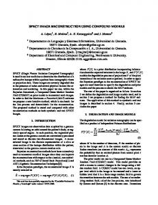
Phase-contrast tomography w ith Radon inversion: edges
BronnikovAlgorithms
I nverse problem of phasecontrast microtomography Object function: f = n – 1
find
f ( x1 , x2 , x3 ) from
• CTF (Cloetens et al, 1999) • TIE (Paganin and Nugent, 1998)
z
I ( x, y ), 0
Phase retrieval, more than one detection plane
• Weak-absorption TIE (Bronnikov, 1999)
FBP, single detection plane
BronnikovAlgorithms
Radon transform solution of TI E d
I ( x, y )
I
Bronnikov, 1999
g ( x, y )
f
1 4
2
d
0
1
d
2
2
( x, y )
I d / Ii 1
gˆ ( s, )d d
g Object f d
BronnikovAlgorithms
Phase-contrast reconstruction in the form of the FBP algorithm Bronnikov, 1999, 2002, 2006
f
Q
Q
2
d
q
g d
q
y x2
y2
0
2D Filtering 2
2
2
2
Gureyev et al, 2004: choice of for linearly dependent absorption and refraction
Backprojection BronnikovAlgorithms
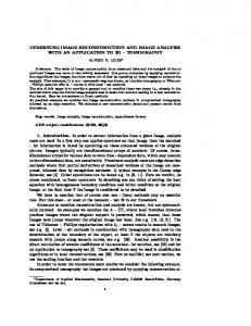
I mplementation at SLS “MBA: Modified Bronnikov Algorithm” Groso, Abela, Stampanoni, 2006
Phase tomography reconstruction (a) and the 3D rendering (b) of a 350 microns thin wood sample using modified filter given in the Eq. (8). The length of the scale bar is 50 µm.
Q
2
2
Validation of the MBA method: (a) Phase tomographic reconstruction of sample consisting of polyacrylate, starch and cross-linked rubber matrix obtained using DPC and (b) using MBA. The length of the scale bar is 100 µm. BronnikovAlgorithms
I mplementation at Ghent University
De Witte, Boone, Vlassenbroeck, Dierick, and Van Hoorebeke, 2009
Radon inversion
“Modified Bronnikov Algorithm” “Bronnikov-Aided Correction” BronnikovAlgorithms
Polychromatic source, mixed phase and amplitude object Air bubbles in epoxy, relatively strong absorption:
6 mm
Reconstruction by the “Bronnikov Filter” with correction
Data provided by Xradia BronnikovAlgorithms
Summary • New developments in theory: parallel-beam CT (synchrotron): the use of NFFT cone-beam CT (microfocus): exact reconstruction with nonplanar orbits; exact ROI reconstruction (Katsevich formula, PI line, Hilbert transform on chords) • New developments in implementation: – ultra-fast 3D reconstruction on multicore processors – (10243 voxels within one-two minutes on a PC) • New developments in coherent methods: robust algorithms for 3D phase reconstruction correction for the phase component
BronnikovAlgorithms