Non-linearity Correction of ADCs in Software Radio Systems Luca De Vito 1,2, Linus Michaeli 3, Sergio Rapuano 1 1
Department of Engineering, University of Sannio, Piazza Roma, 82100, Benevento, Italy Ph.: +39 0824 305817, Fax: +39 0824 305840 E-mail: {devito, rapuano}@unisannio.it, http://lesim1.ing.unisannio.it 2 Telsey telecommunications SpA, Benevento Research Laboratory, via dei Sanniti 1, 82018, San Giorgio del Sannio (BN), Italy Ph.: +39 0824 330145, Fax: +39 0824 330145, http://www.telsey.com 3 Department of Electronics and Telecommunications, Technical University of Košice, Park Komenského 13, SK-04120 Košice, Slovak Republic, E-mail:
[email protected]
A b s t r a c t - The paper presents the results of the experimental validation of a method for digital compensation of ADC non-linearity errors. First, the theory underlying the method is briefly described. Then, the compensation method has been validated both on sinusoidal signals and on 3rd generation mobile telecommunication signals, compliant to 3GPP specifications. I. Introduction In measurement and control systems, in which high-frequency signals are involved, both fast sampling and processing and high accuracy are required. These requirements are particularly relevant in many applications related to signal interception and verification, such as electronic surveillance systems, military communications, emitters intercepting and interference identification. This kind of applications, in fact, is often realized by using software radio receivers [1]. A software radio is a radio system whose channel modulation waveforms are defined in software [2]. That is, the signals to be transmitted are generated as digital waveforms and then converted from digital to analog at base band or intermediate frequency (IF) via a wideband digital-to-analog-converter (DAC). Then, they are possibly upconverted from IF to RF and transmitted. The receiver, similarly, employs a wideband analog-to-digital-converter (ADC) that captures all the channels of the software radio node. The receiver, then, extracts, downconverts and demodulates the channel waveforms using software running on a general purpose processor or a Digital Signal Processor (DSP) [2]. In these systems the ADC characteristics play an important role in the definition of the quality of the communication. The receivers, in particular, require both a high sampling rate and a large dynamic range, because (i) the wideband IF signal should be sampled at a frequency high enough to include all the required channels, and (ii) the spurious free dynamic range (SFDR) should be high enough to ensure that some spurious spectral components with high amplitude do not hide the useful signal. In this scenario, in order to improve the receiver performance, the identification of internal nonlinearity errors of the ADC and the development of methods for their correction in real-time could achieve a considerable SFDR increase. Several papers dealing with the real-time correction of ADC non-linearities can be found in literature. The most part of them achieves a dynamic compensation of non-linearity errors by using a phase-plane [3] or state-space [4] approach. In these cases, the difference between the actual and the ideal code is collected in a look-up table (LUT), as a two-dimensional function of the current output code, and either the slope of the signal or the previous code. This approach requires, however, a large amount of memory [5] in order to build up the LUT. Moreover, some problems arise with (i) the selection of the type and number of the calibration signals [6], and (ii) the compensation of small non-linearities, whose values are smaller than the quantization step. An alternative approach to non-linearity reduction using bayesian filtering has been proposed in [7,8], tested in simulation and implemented on a DSP board equipped with a low frequency, high resolution ADC [9]. In order to prove the capability of the method in more realistic conditions, a test plan on a high frequency, low resolution ADC has been carried out. The experimental tests have been divided in three phases. First, some tests have been carried out on a converter by using sine-wave signals to identify the capability of the method of compensating the intrinsic nonlinearity of the ADC, which is below the LSB [9]. A second group of tests has been
x
Nonlinearity
Ideal quantizer
k
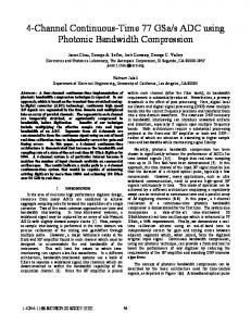
Actual ADC Figure 1. ADC model, used for deriving the correction method.
realized with sine-wave signals by introducing a self-built analog nonlinearity affecting few codes but with an amplitude of several LSBs and considering the ADC as ideal [9]. Finally, an experimental phase has been carried out with a new analog non-linearity, which occupies the whole full scale range of the ADC. During this phase sine waves and Universal Mobile Telecommunication System (UMTS) signals, based on the Wideband Code Division Multiple Access (W-CDMA) technique, have been used. The first two phases already showed a relevant SFDR increase [9]. In the paper the results of the last phase are presented. The method has been first validated on simulated W-CDMA signals. Then, it has been verified on a test bench consisting of a PC data acquisition board equipped with an 8-bit 1 GS/s A/D converter. In order to consider the ADC as an ideal one, a self-built analog distortion circuit, whose non-linearity is much greater than the intrinsic non-linearity of the ADC, has been used. In the next Sections the method is briefly recalled, then the results obtained by the simulation phase are given. Finally, the results of the characterization phase using actual signals are presented. II. The method For the scope of the present work, the effect of the non-linearity on an actual ADC has been modelled as a distorting channel in which the output of an ideal quantizer x is mapped to the actual output k (Fig.1) [8]. In this case, an estimation of the original code x can be obtained by the following formula [8]:
xˆ = E{x | k } =
2 N −1
∑ x ⋅ p(x | k ) ,
(1)
x =0
where E{} is the expected value operator, N is the number of bits of the converter, p(k) and p(x) are the probabilities of the actual code k and the ideal one x, respectively. p(x|k) is the conditional probability of x, given k. The conditional probability p(x|k) is obtained by means of the Bayes theorem, as follows:
p(x | k ) =
p (k | x ) ⋅ p(x ) p(k | x ) ⋅ p(x ) = N . 2 −1 p(k ) p (x ) p (k | x )
∑
(2)
x =0
If dither is applied, in order to reduce quantization noise and small scale non-linearity errors, an estimate of the ideal code x can be found by over-sampling, applying a Bayesian filter and using a smoothing window of length 2Ls+1 to remove the dithering: xˆ[i ] =
2 −1 1 1 p(k [i + j ] | x[i + j ]) p(x[i + j ]) . xe [i + j ] = x[i ] 2 Ls + 1 j = − L 2 Ls + 1 j = − L x[i ]= 0 p(k [i + j ]) Ls
N
Ls
∑
∑∑
s
(3)
s
In this case a simple rectangular smoothing window has been chosen [8]. The matrix containing p(k|x) conditional probabilities can be evaluated in a calibration phase starting
from the code transition levels as shown in [7]. Sine wave histogram test procedure, reported in [10], has been used for estimating code transition levels. III. Simulation results A simulation study has been carried out in MATLAB language on W-CDMA signals, according to the block scheme reported in Fig. 2. A W-CDMA signal is generated in compliance with 3GPP specifications [11] at an IF frequency of 10.32 MHz and double precision samples. Then, it is quantized using both an 8-bit ideal ADC model and an 8-bit actual ADC model, with a simple nonlinearity 40 codes wide and 6 codes high, having the INL shown in Fig. 3. After the quantization, the method for the non-linearity correction has been applied and the SFDR referred to the carrier frequency has been evaluated, as in [10]. Fig. 4 shows the Power Spectral Density (PSD) of the signal before and after the non-linearity correction, respectively. It can be noted a relevant improvement of more than 20 dB in the SFDR, referred to the carrier frequency. Actual ADC model W-CDMA signal generation
Ideal quantization
Non-linearity
Bayes correction algorithm
Non-linearity parameters evaluation
Ideal ADC model Ideal quantization
Figure 2. Block scheme of the procedure adopted for the simulation tests.
IV. Experimental results The test bench consists of a development system composed of a PC based on a Pentium IV 1,7 GHz CPU and a Signatec PDA1000 data acquisition board, equipped with a 1 GS/s 8-bit flash ADC. As it can be seen in Fig. 5, signals are generated by an Agilent E4438C vector signal generator, then, sent to a self-built analog board which is used for corrupting the signal with a known non-linearity. An electrical scheme of this circuit is given in Fig. 5 in enlarged view. Data are collected by the PC and corrected. In a first phase, some experimental tests have been conducted using a 15 MHz sine-wave signal. The signal has been acquired using a 250 MS/s sampling frequency. The integral non-linearity (INL) has been evaluated by means of the sine-wave histogram test procedure [10]. From the INL diagram of Fig.6a the INL introduced by the non-linearity circuit can be clearly observed. Fig. 6b shows the results of the correction method. In particular, a reduction in the second harmonic of 28.8 dB can be observed, while the SINAD increase is equal to 23.52 dB. 40
0
30
Power Spectral Density [dB/Hz]
1
INL [LSBs]
-1 -2 -3 -4 -5 -6 -7 0
50
100
150 Codes
200
250
Figure 3. INL of the non-linearity model.
20
Before correction
10
After correction
0 -10 -20 -30 -40 0
20
40 Frequenza [MHz]
60
80
Figure 4. PSD of a W-CDMA signal before and after the correction.
Non-linearity board
Agilent E4438C Vector Signal Generator
Signatec PDA1000 Data Acquisition Board
PC
Figure 5. Test setup for the correction method.
Then, a second phase of tests has been carried out using W-CDMA signals compliant to the 3GPP standard [11]. Signals coming from a single Dedicated Physical Channel have been generated at a 15 MHz IF and acquired with a 250 MS/s sampling frequency. In Fig. 7 the PSD of the signal before correction is reported in grey colour, while for the PSD of the signal after the correction is shown in black. The graphs are reported in dB referred to the higher harmonic component. How it can be seen, the effect of the non-linearity is well compensated and the SFDR is increased from 14.88 dB to 36.08 dB. V. Conclusions The experimental validation of a method for digital compensation of high frequency, low resolution ADC non-linearity errors has been presented. In particular the compensation method has been validated on 3rd generation mobile telecommunication signals, compliant to 3GPP specifications and a SFDR increase of more than 20 dB has been achieved both on simulated and on actual W-CDMA signals. Further work is directed to experimental investigations using different telecommunication signals and to the integration of this method with some specific measurement method for 3G systems.
a) INL [LSBs]
Amplitude [dB]
b)
Codes
before correction after correction
Frequency [MHz]
Figure 6. (a) INL introduced by the non-linearity board, and (b) the results of the correction method for a sinusoidal test signal.
Amplitude [dB]
before correction after correction
Frequency [MHz] Figure 7. Power spectral density of a W-CDMA signal before and after the correction.
References [1] [2] [3]
[4] [5]
[6]
[7]
[8]
[9] [10] [11]
Pentek web site: www.pentek.com. J. Mitola III, “Software radio – cognitive radio”, IEEE Communication Magazine, vol. 33, No. 5, pp. 26-38, 1995. T. A. Rebold, F. H. Irons, “A phase plane approach to the compensation of high-speed analog-todigital converters”, Proc. of IEEE Int. Symp. on Circuits and Systems, Philadelphia, PA, USA, pp.455-458, 1987. F. H. Irons, D. M. Hummels, S. P. Kennedy, “Improved compensation for analog-to-digital converters”, IEEE Trans. on Circuits and Systems, vol. 38, No. 8, pp.958-961, 1991. H. Lundin, M. Skoglund, P. Händel, “Minimal total harmonic distortion post-correction of ADCs“, Proc. of 8th International Workshop on ADC Modelling and Testing, Perugia, Italy, pp.113-116, 2003. C. L. Monteiro, P. Arpaia, A. C. Serra, “Dual tone analysis for phase-plane coverage in ADC metrological characterization”, Proc of 20th IEEE Instr. and Meas. Tech. Conference, Vail, CO, USA, pp. 1334-1339, 2003. P. Daponte, R. Holcer, L. Horniak, L. Michaeli, “Using the interpolations method for noise shaping A/D converters”, Proc. of 6th Workshop on ADC Modelling and Testing, Lisboa, Portugal, pp.134-137, 2001. P.Daponte, R. Holcer, L. Horniak, L. Michaeli, S. Rapuano, “Using an interpolation method for noise shaping in A/D converters”, Proc. of 4th IEE ADDA – 7th IMEKO TC-4 Workshop on ADC Modelling and Testing, Prague, Czech Rep., pp. 147-150, 2002. L. De Vito, L. Michaeli, S. Rapuano, “Real-time implementation of a method for ADC nonlinearity reduction”, paper accepted for publication on Measurement Journal. IEEE 1241 Standard for “Terminology and test methods for analog-to-digital converters”, 2001. 3rd Generation Partnership Program. Technical Specification Group Radio Access Networks. “Universal Mobile Telecommunications System (UMTS); Spreading and modulation (FDD)”, 3GPP TS 25.213, v5.2.0, 2002.