International Global Navigation Satellite Systems Society IGNSS Symposium 2007 The University of New South Wales, Sydney, Australia 4 – 6 December, 2007
Impacts of GPS-Based Synchronization Degradation on Cellular Networks Faisal A. Khan School of Electrical Engineering & Telecommunications, University of New South Wales
[email protected]
Andrew G. Dempster School of Surveying & Spatial Information, University of New South Wales
[email protected]
ABSTRACT GPS timing receivers have long been relied upon by various communications networks for achieving synchronization among the network nodes. Cellular networks, particularly CDMA cellular networks, actively employ GPS timing receivers for making their time critical decisions, particularly handoff. Operations and parameters which set the network quality of service (QoS) require that these GPS receivers provide timing solution up to nano-second accuracy. Therefore, GPS timing receiver are required to provide a disturbance free solution. However, as all GPS receivers communicate with GPS satellites over the air interface; these are inevitably vulnerable to RF interference. This interference disturbs the timing receiver’s performance, degrading its solution. This paper appreciates this issue, identifies the problems caused and discusses in detail the performance degradations of cellular networks due to instability of timing signals from GPS. KEYWORDS: GPS timing receiver, Synchronization degradation, CDMA Cellular Network, GSM Cellular Network, UMTS Network.
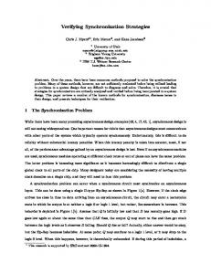
1. INTRODUCTION Synchronization serves as a pacemaker for digital communications networks. Current communications networks and upcoming Next Generation Networks, particularly cellular networks like the CDMA2000 1xEV-DO system, are associated with large coverage areas, increased complexity and high data rates. These call for precise and accurate time alignment of operations. Throughput and Quality of Service (QoS) of these networks increase with the performance of synchronization devices. Synchronization has not been given due attention in past by network operators. But it is becoming inevitable that current cellular systems like CDMA and GSM could even provide high QoS without synchronization. GPS-based synchronizers, due to their precision, have long been relied upon by such communications systems for fulfilling their timing/frequency requirements. Although other synchronization sources like LORAN C or atomic standards can also cater for timing, those are associated with drawbacks like high installation, operations and maintenance costs. QoS and Key Performance Indicators (KPI) of various communication systems depend upon internetwork and intra-network synchronization, which is derived from these GPS based synchronizers. But, like most other technologies, GPS timing receivers used in these synchronizers are not fail-safe. GPS greatly relies on information transfer over the air interface. This wireless nature of GPS communications links and the weak power levels of GPS signals make them vulnerable to RF interference. Any electromagnetic radiation source can act as an interference source, if it can emit potential radio signals in the GPS frequency bands (Landry et al., 1997). GPS timing receivers, in particular, are installed at sites like cellular base stations, which are shared by other RF antennas. Such an environment enhances vulnerability of GPS receivers to interference (Bullock et al., 1997). Figure 1 shows an installation of a GPS timing receiver antenna at a cellular base station. Increased interference in GPS bands can potentially reduce SNR for GPS signals disrupting the code/carrier tracking process. Such disruptions in the code and carrier tracking loops lead to measurement errors degrading the timing solution accuracy or can even cause tracking loops to lose lock altogether.
Figure 1. Antenna for GPS timing receivers, installed at a cellular base station in Islamabad, Pakistan.
In (Khan, 2007), it was identified that RF interference affects GPS timing receivers in three distinct phases. Phase-1 corresponds to a situation where the interference power levels remain within manageable limits and do not cause noticeable degradation in the timing solution. It was also noticed that a GPS receiver in this phase typically does not lose lock with any incoming satellite signal. Phase-2 corresponds to the situation where the GPS receiver starts losing lock to incoming satellite signals. In this phase, the timing solution degrades and deviates further from the true time, as the receiver loses lock with incoming satellite signals. Phase-3 corresponds to a situation where interference increases to a level that the GPS receiver loses all the locked satellites, and provides solution on the basis of its on-board oscillator. During this phase, the timing solution from the receiver does a random walk and the solution drifts away from the true time following the on-board crystal oscillator characteristics. In this paper, it is investigate how performance of cellular networks, especially CDMA cellular networks, would be affected in the case of degradation of the timing solution. After introducing the problem in section 1, section 2 discusses the ways in which communications networks obtain timing signals from GPS-based synchronizers. In section 3,4 and 5, impacts on different types of networks are examined. Finally section 6 concludes this paper.
2. GPS Timing for Cellular Networks: GPS timing receivers generate a pulse per second (PPS) signal, the rising or the falling edge of which is aligned with the GPS second to nano-second level accuracy. This PPS is used to discipline an on-board oscillator, by continuously steering it to remain in synchronization with the GPS Time. The short term stability of the local oscillator is complemented by the long term stability of the GPS timing receiver. The output of this GPS disciplined oscillator (GPS-DO) is then used by the networks’ timing clocks and frequency synthesizers to generate the required synchronization signals. These synthesizers consider the clock signal from GPSDO as the reference signal and ensure that the output frequencies are generated with the same stability and accuracy as the input reference signal (Torrieri, 2005). This implies that any degradation in the input reference frequency will also be reflected in the output of the frequency synthesizer. Similar will be the case of the clock signal generators. These unstable/inaccurate/imprecise outputs of the synthesizers/clock generators, when fed to the network for synchronizing the network elements, will degrade the KPIs of that network. It can be inferred that the stability of the PPS can only be improved by GPS-DO, while frequency synthesizer does have any effect. It has been identified that GPS timing receivers can still provide a degraded solution with lesser accuracy and precision, even when locked to the incoming satellite signals (Khan, 2007). If the GPS timing receiver loses lock, there is generally no backup source of timing used by the communications networks except the local oscillator on-board the GPS based clocks. With all of its vulnerabilities, a large number of telecom operators still rely on the GPS-DO as their stratum-1 reference (a clock with an accuracy of 1x10-11), because the alternatives are either associated with high costs for widespread deployment (e.g. cesium oscillators) or are simply unable to meet the required accuracy without periodic calibration (e.g. rubidium or crystal oscillators). It, therefore, becomes interesting to study the impacts of GPS-DO solution degradations on the performance of the communications networks. In the following sections, the effects of this degraded synchronization on cellular networks’ performance are investigated.
3. Impacts on CDMA Cellular Networks: 3.1 CDMA Synchronization Requirement and Operation:
The CDMA cellular system is one of the major employers of the GPS timing solution, utilizing it for Network node (Base station (BS)) identification, RF signal encryption, frequency and timing accuracy, data synchronization, providing UTC time and date to users and assisting mobiles in E911 location determination (Greene, 2006). In the CDMA cellular system, each node (BS) uses the same PN code. Here BS are identified on the basis of a unique time-delay offset (TDO) (measured relative to zero-offset code) with which they transmit their signals. If any BS transmits the pilot/data signals at a time other than the assigned TDO, it is likely that its code will line-up with code from any other BS. This would cause interference in that code, as all the BS use the same PN code. Mobile stations (MS) use the pilot signal, transmitted by BS with the assigned TDO, as a coherent phase reference for decoding all the other data sequences from that BS. The MS timing is controlled by the BS, termed as the associated BS, from which the strongest signal is received. MS use a 3-finger RAKE receiver to receive data and a searcher receiver to search for pilot signals from BS. This searcher receiver searches in the time domain around the expected time of arrival of the desired pilot signal. Once the pilot signal from a BS is acquired and its TDO is determined, one of the RAKE fingers can be assigned to that BS, suggesting where to find its signals in the time domain. Signals addressed to an MS can be transmitted through up to three BS located in the vicinity of that MS. These signals are then diversity combined to obtain a stronger signal (Lee et al., 1998). An important operation which needs to be defined here is Soft Handoff. The MS’s searcher receiver continuously searches for new pilot signals from BS with good strength. If this signal strength exceeds the add threshold, this BS is listed in the candidate set. During a call, if the strength of a signal from a BS in the candidate set exceeds that of a serving BS, the serving BS is notified and the new BS also starts contributing to/handling the call in addition to the serving BS. BS handling the call are listed in a set called active set. If the MS moves towards the edge-of-coverage (EoC) of a serving BS, the received signal strength is decreased at MS. If this signal strength from that BS decreases below the drop threshold and stays there for a pre-specified time, it is removed from the active set, and the call is no longer established through that BS. In this way, an established call can be handled through more than one BS. Also, call control (association) can be transferred (handoffed) from one BS to another, if its received signal level is reduced at the MS. This avoids dropping of a call, because as one BS is dropped, another BS is already serving the call.
3.2 Synchronization Degradation Effects:
In (Khan, 2007), a hypothesis was proposed and confirmed as detailed above. This hypothesis categorized interference effects into three phases, based on the extent of synchronization degradation. On the basis of these phases, one can classify the synchronization degradation effects on CDMA cellular networks into three categories: 3.2.1
Large synchronization errors:
Large synchronization errors only occur when the GPS timing receiver operates in phase-3. Above mentioned hypothesis dictated that a GPS receiver’s timing solution potentially drifts
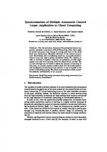
away from true time, in phase-3, as the introduced interference forces the GPS receiver to lose lock. This drifting of timing solution results in large synchronization errors. For the particular case of the test timing receiver, used in (Khan, 2007), a lower bound can be considered to be 450ns, as the test receiver lost lock before 450ns for all runs. However, for a variety of GPS based synchronisers, this bound will vary depending upon the type of the received interference and the receiver used. The MS, in this situation will face the following problems. Problems with Tracking of Signals from Non-Associated BS – The MS timing is continuously steered by the associated BS through a synchronization channel (Lee et al., 1998). If there is a problem with the GPS based clock of that BS, the same problem would be replicated in the MS's clock. Due to such problems, the BS clock and eventually the MS clock would experience drift with respect to the system time. This clock drift would cause the MS to lose the tracked signals from other (non-associated) Base Stations, eventually resulting in unsuccessful handoffs and dropped calls. Problems with Acquisition of New Signals from Non-Associated BS – An associated BS assigns the MS a time-window to search for the pilots from other BS. As successive codes are offset by 64 bits, the maximum size this window can have is ±32 bits, which translates to 52.0833 µs (±26.04167µs). Consider a situation where an associated BS instructs an MS to search for some other BS in a window located at Tm ± 26.04167µs (where Tm could be any multiple of 64-bit duration). Now if the associated BS receives a degraded synchronization signal, it’s time as well as the time of the associated MS would drift away from the system time. This would cause the MS to search at some incorrect point in time for the desired pilot. It is highly likely that this would eventually result in failure, as any pilot may not be present in that time window. It is possible that the MS may succeed in acquiring a pilot from some non-desired BS (which it can, as all the BS are using same PRN with different time-delay offsets). In this case, it will try to remain in synchronization with the new BS, but would eventually lose it due to drift in its clock with respect to that BS clock (and the system time). Also, the sync channel message carries the offset value for a particular BS. This value will not match with the offset value assumed by MS, which would also cause termination of tracking that BS by MS. Soft Handoff and Associated Problems Due to Degraded Synchronization – The MS clock is synchronized/controlled by the associated BS. If the clock stability for that associated BS clock degrades, it is likely that the MS would lose synchronization with all other nonassociated BS (as MS clock follows associated BS clock). In this case, the MS would neither be able to continue communications with any other non-associated BS nor would it be able to acquire pilot signals from any new BS, due to the reasons mentioned above. Now if the MS moves beyond EoC of the associated BS, instead of performing handoff, its call would be dropped as no other BS would be serving that MS. Therefore, loss of synchronization for a BS would result in loss of any new acquisitions by all associated MS. However, active calls would still remain established as long as the MS do not move beyond EoC for that BS. In phase-3, the generated timing solution is based on the local oscillator on-board GPS-DO modules. In order to quantize, how long would it take for these modules to exceed the thresholds set by CDMA standards (3GPP2, 2004), drift characteristics of the on-board oscillators need to be considered. Fig. 2 depicts Maximum Time Interval Error (MTIE) for a variety of oscillators. MTIE is defined as the maximum phase difference between the measured and the reference signal (peak to peak value) in given observation time. It can be inferred from this graph that if appropriate drift rate prediction based algorithms are not used
for disciplining the local oscillator, these would not be able to provide holdover for longer durations. Standard versions of commercially available Oscillators like Oscilloquartz’s OSA 8663 OCXO, which is used by many GPS-DOs, claim to provide holdover of 3µs for barely more than a day (as can be seen from Fig. 2). Also, Symmetricom’s TimeSource 3500 which employ Rb Oscillator claim a holdover of 3µs to GPS for 72 hours. Longer holdover periods call for high prices and non-economical solutions. 10
-3
MTIE (s)
OScilloquartz's OCXO 8663 10
-4
10
-5
10
-6
OScilloquartz's OCXO BVA 8600 OScilloquartz's Rb RMO
0.05ppm Slope
10
-7
10
-8
CDMA Worst Case Requirement (3µs)
Nominal CDMA Requirement (3µs)
-9
10 -2 10
10
0
2
4
10 10 Observation Time (s)
6
10
10
8
Figure 2. MTIE for various Oscillators. Data Obtained from www.oscilloquartz.com 3.2.2
Medium synchronization errors:
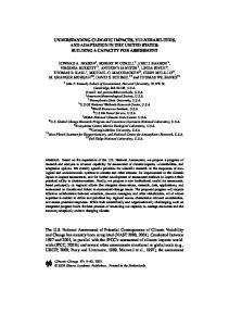
Medium synchronization errors can be experienced, when the timing receiver operates either in phase-2 of hypothesis or in the vicinity of phase-1 and phase-2 boundary. In this situation, although the receiver remains locked with at least one incoming signal, it produces a PPS with less stability and precision. For the test receiver, PPS variations during phase-2 ranged from 20ns to 450ns, due to the introduced interference (Khan, 2007). Such a PPS when used by the clock/frequency synthesizers of a CDMA system, as timing and frequency reference, can introduce errors in their output. These errors may include: Frequency Violation – As the frequency synthesizers use output of PPS disciplined oscillators as reference for generating carrier frequencies, any instability or impreciseness in that PPS would cause incorrect frequency generation. The CDMA cellular system allows an error margin of 0.05ppm (translating to ±45Hz error at 900 MHz carrier frequency) (3GPP2, 2004). Also, MC-CDMA is in use for cellular communications. This employs orthogonal carriers, and is much more vulnerable to frequency violations than ordinary CDMA. Considering these issues, any errors in frequency synthesis due to in-stable reference would introduce frequency violations, resulting in inter-carrier interference into signals from neighbouring BS. A typical clock signal/carrier frequency synthesis process from GPS timing solution is shown in Figure 3. It can be noticed that the relationship of GPS’s PPS and the generated clock signal/carrier frequency depends on the microprocessor’s (µP) algorithm. For instance, based on the phase
error of the GPS and the local oscillator’s PPS, an MMSE based function can be employed to generate the control signal for local oscillator and to predict the deviation (in ppm) of the generated clock signal and carrier frequency from the desired value. However, such an effort is beyond the scope of this work. It may also be noted that the GPS-DO used here can mitigate only short-term instabilities introduced in phase-2 due to received interference; however, many GPS based synchronizers use longer averaging times.
GPS
PPS
GPS Disciplined Oscillator PPS
GPS PPS
Clock Generator
Divide by N
Phase 10MHz
µP
D/A XO Control
Frequency Synthesizer
Local Oscillator Time
Figure 3 – GPS-DO based Clock Generator and Frequency Synthesizer
Effects on Signal-to-Noise Ratio (SNR) – Increasing the number of carriers in a multi-carrier system makes it vulnerable to synchronization errors (Tomba et al., 1996), and MC-CDMA is no exception. The lack of synchronization between the transmitter clock and receiver sampling clock, in a multi-carrier system, also introduces severe errors in transmissions. Such a situation can occur with an MS and a serving (non-associated) BS, if the clock of the MS is drifting with respect to true time, due to stability issues with associated BS clock. There can be two types of synchronization errors in MC-CDMA: timing errors and carrier-phase errors. Considerable degradations can occur due to time-varying timing and carrier phase errors (Steendam et al., 1999). It may be noted that the length of duration of phase-2 depend upon the type of interference. e.g. a narrow band interference will keep the receiver in phase-2 for a longer duration than an interfering signal with a wider bandwidth. 3.2.3
Small synchronization errors:
When GPS timing receiver is operating in phase-1 region of hypothesis, clock stability errors are not noticeable. Minor instabilities are normally removed by the PLL in the GPS-DO. Therefore, no problems are caused in this situation.
4. Impacts on GSM Cellular Networks: 4.1 Synchronization Requirement:
The GSM network architecture consists of three major nodes: Network & Switching Subsystem (NSS), Base Station Subsystem (BSS) and Mobile Station (MS). In the past, internode synchronization had not been given due attention. Now, however, it has been identified by measurement and control specialists that problems due to lack of synchronization are increasing at the above mentioned nodes (Clark, 2000). It is now required that synchronization requirements are met by both NSS (should comply with G.811 ITU standard) and BSS (should comply with G.812 ITU standard) (Symmetricom, 2006). GSM networks have relied on T1/E1 backhaul for some time for disciplining their local oscillators. However, the decreasing quality of synchronization from such sources has imposed increasingly regular and costly maintenance (Dropping, 2005). Due to such reasons, GSM networks have started relying on GPS based clocks over the recent years. Currently, GSM operators employ three major types of synchronization sources: GPS-based Re-timers, Embedded stand alone clocks and Packet based synchronization protocols. All of these three types use GPS based clocks as their main synchronization reference. Figure 4 shows one of the typical synchronization schemes at a GSM Mobile Switching Centre (MSC). The Synchronization Supply Unit (SSU), which is used to as the Primary Reference Clock (PRC), employs GPS receivers. It can be seen that, at an MSC, Central Clock Generator (CCG), Signalling System Network Controller (SSNC), Base Station Controller (BSC) and Synchronous Digital Hierarchy (SDH) obtain the synchronization clock signals from GPS receivers through an SSU. Here, SSU is typically a G.811 clock source when locked to GPS. GPS
SSU
Ref 1 Ref 2
LTG LTG
Ref 1 Ref 2
CCG-0/1 (MSC)
SSNC
BSC
SDH
Figure 4 - Clock Distribution Configuration
4.2 Synchronization Degradation Effects:
It is now well accepted that the competition in the GSM service providers has increased tremendously, which has enhanced the rate of user churning from one service provider to another. One of the major factors enhancing this rate is degradation in QoS particularly increased number of dropped calls. For meeting the desired network QoS requirements, the ETSI GSM standard requires the Base Transceiver System (BTS) to maintain a stability of 50ppb for both frequency synthesizers and the clock generators. Failing this requirement can result in increased number of dropped calls due to lack of synchronization over the air interface. Once the GPS based synchronizer enters the phase-3, it will not be able to meet the requirements of ETSI GSM standard, due to inherent drift of the local oscillator from true time. However, during phase-2, as said above, will mitigate the short-term instabilities, preventing any significant degradations to KPIs. The handover performance of an Omnitel-Vodafone GSM network was studied for the investigation of degraded synchronization effects (Bregni et al., 2003). Mean Opinion Score (MOS) and Speech clipping were observed for certain number of calls, for different values of fractional frequency accuracy. Here, MOS indicates the listening quality, Speech clipping indicates degree of speech distortion and fractional frequency accuracy (∆f/f) refers to the ratio of frequency error ∆f to nominal frequency f. Table 1 below shows the MOS, for calls undergoing handover, for different values of ∆f/f. It can be noticed that while the error remained small (∆f/f), more than 85% of the calls experienced good handover and only 2 calls out of 16 experienced a bad handover. As the frequency error was increased upto 1 ppm and further to 10ppm, it was observed that handover performance degraded significantly. There was a 30% – 35% increase in the number of calls experiencing bad listening quality during the handover.
MOS
Fractional Frequency Accuracy (∆f/f) Bad (0-1) Poor (1-2) Fair (21-30) Good (31-40) Excellent (41-50)
0 2 0 0 14 0
0.1 ppm 2 0 0 14 0
1 ppm 6 1 0 9 0
10 ppm 6 2 0 8 0
Table1 - MOS Values for Different ∆f/f
Similarly, Table 2 presents the quality of speech clipping against different values of ∆f/f for 16 calls during the handover, excluding the dropped off calls. It can be noticed that while the frequency error remained up to 0.1 ppm, there 87.5% of the calls did not experience any bad quality. However, as this error was increased up to 1 – 10 ppm, the quality of the calls suffered degradation. The number of calls considered for the study was very low. A similar study for a large number of calls can provide a clearer view of the situation. Dropped calls and distorted speech are not the only major problems caused by degraded synchronization signals from GPS based clocks. Transmission of corrupted data and spectrum violation resulting in increased adjacent channel interference are also becoming significant due to such timing and frequency
synchronization problems. Fractional Frequency Accuracy (∆f/f) 0 14 0 0 0
Speech Clipping
1–5% 5 – 10 % 10 – 15 % 15 – 20 %
0.1 ppm 14 0 0 0
1 ppm 9 0 1 5
10 ppm 8 1 1 3
Table 2 - MOS Values for Different ∆f/f
5. Impacts on UMTS Cellular Networks: In addition to GSM and CDMA networks, UMTS based networks are also employing GPS based clocks for meeting QoS requirements (Schneuwly, 2004). UMTS systems have strict timing requirements at each of their nodes. It is required that fractional frequency deviation should be kept less than 0.01 ppb and 50 ppb at interfaces between the Core Network (CN) node and Node B, and between Node B and Mobile Station (MS) respectively (as depicted in Figure 5). In UMTS as well, degraded synchronization introduces similar problems as in case of GSM and CDMA cellular Networks. These problems include: 1. Increased handover failures due to lack of synchronization of Node B. Degradation in synchronization directly affects the number of calls/sessions lost during the handover. 2. Spectrum violations caused due to incorrect reference of frequency synthesizers at Node B, resulting in carrier frequency overlap and Adjacent Channel Interference (ACI). 3. Data corruption due to lack of frame synchronization processes.
Core Network A MS
C
B Node B (Base Station)
Radio Network Controller
Synchronization Requirements (in fractional frequency): A – 5x10⁻⁸ (50 ppb) B – 1x10-11 (0.01 ppb) C – 1x10-11 (0.01 ppb)
Figure 5. Synchronization Performance Requirements for UMTS
6. CONCLUSION: In this paper, the effects of synchronization degradation on CDMA, GSM and UMTS cellular networks were considered. These networks, especially CDMA cellular networks, rely on GPS
based synchronizers. This paper identified that such synchronizers are vulnerable to RF interference, which could degrade their timing solution. It was discussed in detail that, for cellular networks, that this degraded synchronization could lead to poor QoS and traffic handling capability, and reduction of network KPIs (such as call setup success rate and drop call rate). However, it may be noted that presence of GPS-DO would alleviate the effects in phase-2 upto an extent dictated by the short-term stability of the disciplined oscillator. The discussion presented in this paper motivates the need of further study for reducing GPS vulnerability to RF interference. REFERENCES Landry RJ, Renard A, “Analysis of Potential Interference Sources and Assessment of Present Solutions for GPS/GNSS Receivers”, 4th Saint-Petersburg on INS, 1997. Bullock JB, King TM, Kennedy HL, Berry ED, Zanfino G, “Test Results and Analysis of A Low Cost Core GPS Receiver for Time Transfer Applications”, IEEE Frequency Control Symposium, 1997. Khan FA, “Behavior of the GPS Timing Receivers in the Presence of Interference”, to appear in ION GNSS 2007 Khan FA, Dempster AG, “Effects on CDMA Network Performance due to Degradation of GPS based Synchronization”, to appear in 7th International Symposium on Communications and Information Technologies, 2007 Khan FA, Dempster AG, “Effects of GPS Based Sync Degradation on Communications Networks”, submitted to IEEE Transactions on Communications, September 2007. Torrieri D, “Principles of Spread-Spectrum Communication Systems”, 1st Edition, Springer, 2004. Greene B, “Wireless Cellular Communications and Next-Generation GPS”, Next-Generation GPS Forum, U.S. Dept. of Commerce, 2006. Lee JS, Miller LE, “CDMA Systems Engineering Handbook”, Artech House, 1998. 3rd Generation Partnership Project 2 (3GPP2), “Recommended Minimum Performance Standards for cdma2000 Spread Spectrum Base Stations: Release B,” C.S0010-B, Version 2.0, 2004. Tomba L, Krzymien W, “Effect of Carrier Phase Noise and Frequency Offset on the Performance of Multicarrier CDMA Systems”, International Conference on Communications, 1996 Steendam H, Moeneclaey M, “The Effect of Synchronization Errors on MC-CDMA Performance”, International Conference on Communications, 1999. Clark A, “Clocking on for GSM”, Electronic Times, 2000. Symmetricom, “Timing and Synchronization in Next-Generation Wireless Networks”, white paper, Symmetricom Web (www.symmetricom.com), 2006 Dropping B, “Reducing churn in GSM networks”, Symmetricom, 2005. Bregni S, Barbieri L, “Experimental Evaluation of the Impact of Network Frequency Synchronization on GSM Quality of Service during Handover”, GlobeCom, 2003. Schneuwly D, “The Synchronization of 3G UMTS Networks”, Application Note, Oscilloquartz, Switzerland, 2004.