The AADS is currently tested in simulations at Mars, ... and structural limits, such as freestream heating rate, solar array temperature, dynamic pressure, .... its multiple vehicle, multiple phase simulation capability that features generalized ... where Ãq is the freestream heating rate, Ï is the atmospheric density, and V is the ...
AAS 11-476
IMPLEMENTATION AND SIMULATION RESULTS USING AUTONOMOUS AEROBRAKING DEVELOPMENT SOFTWARE Robert W. Maddock*, Alicia Dwyer Cianciolo*, Angela Bowes*, Jill L. H. Prince*, and Richard W. Powell† An Autonomous Aerobraking software system is currently under development with support from the NASA Engineering and Safety Center (NESC) that would move typically ground-based operations functions to onboard an aerobraking spacecraft, reducing mission risk and mission cost. The suite of software that will enable autonomous aerobraking is the Autonomous Aerobraking Development Software (AADS) and consists of an ephemeris model, onboard atmosphere estimator, temperature and loads prediction, and a maneuver calculation. The software calculates the maneuver time, magnitude and direction commands to maintain the spacecraft periapsis parameters within design structural load and/or thermal constraints. The AADS is currently tested in simulations at Mars, with plans to also evaluate feasibility and performance at Venus and Titan.
INTRODUCTION Several past NASA missions have used a technique known as aerobraking to reduce the fuel required to deliver a spacecraft into a desired orbit around a target planet or moon with an appreciable atmosphere. Aerobraking was first demonstrated at Venus with Magellan in 1993 and then to achieve the science orbit of three Mars orbiters: Mars Global Surveyor, Mars Odyssey, and Mars Reconnaissance Orbiter. Instead of using only the propulsion system to decelerate the spacecraft, aerobraking is used after the initial orbit insertion to further decelerate the spacecraft by using aerodynamic drag. The spacecraft traverses the upper atmosphere of the planet or moon multiple times while controlling periapsis altitude using small propulsive maneuvers at apoapsis in order to hold the spacecraft within a specified corridor at periapsis. This corridor is designed to keep the spacecraft safely within specified structural and/or thermal design limits until the desired orbit is achieved. Although aerobraking itself reduces the propellant required to reach the final orbit, this reduction comes at the expense of additional mission time (typically 3–6 months), a large mission operations staff, and significant Deep Space Network (DSN) coverage. This combination of critical resources results in an expensive operational phase of a mission. The concept of somehow automating this complex process has been studied for over a decade1,2. The NASA Engineering and Safety Center (NESC) is developing the Autonomous Aerobraking Development Software to demonstrate that many of the aerobraking operation functions, which have typically been performed on the ground, can be performed autonomously onboard the spacecraft, thus reducing the * †
NASA Langley Research Center, Engineering Directorate, M.S. 489, Hampton, VA 23681. Analytical Mechanics Associates, 303 Butler Farm Rd., Hampton, VA 23666.
1
required ground staff and the required DSN coverage, potentially saving millions of dollars in project costs3. Aerobraking operations occur in four phases. The first phase, referred to as “walk-in”, begins after the propulsive capture and is used to gradually lower the periapsis until the sensible atmosphere is encountered and can be initially characterized. The second phase is the main aerobraking phase and guides the spacecraft from the initial long period orbits to short period orbits using maneuvers to remain within the operational corridor. The third phase, often referred to as the “endgame”, adds a minimal orbital lifetime to the spacecraft safety constraints to allow adequate time to respond to a spacecraft problem without danger of deorbiting. The final phase is the termination of aerobraking by raising periapsis out of the atmosphere. Operations during the main aerobraking phase can be broken down into daily and weekly operations. The weekly operations determine the flight corridor design for the next week, and the daily operations are used to determine any required periapsis adjust maneuvers to maintain the spacecraft within the design corridor. The Autonomous Aerobraking Development Software (AADS) currently being developed through NESC would allow for these daily ground operations to be moved to the spacecraft and performed autonomously. AEROBRAKING MISSION RUNOUT The mission runout is a ground based simulation of a reference mission designed to achieve the final desired orbit conditions via aerobraking while maintaining the mission operational constraints and the margin required for the spacecraft design limits4. Desired final orbit conditions can include altitude, inclination, argument of periapsis, and longitude of the ascending node required to attain a specific local mean solar time (LMST) orientation, or combinations of the above. Spacecraft design and mission operational constraints may consist of spacecraft thermal and structural limits, such as freestream heating rate, solar array temperature, dynamic pressure, power, attitude, and capability to handle atmospheric density fluctuations, as well as orbit lifetime requirements, maneuver frequency restrictions, maneuver magnitude limitations, and required propellant remaining post aerobraking to achieve mission objectives. The mission runout begins after walk-in and lasts until the final desired orbit conditions are achieved. A corridor is determined based on a heat rate indicator, dynamic pressure, or temperature to keep the spacecraft within the appropriate margins. Maneuvers are performed at apoapsis that raise or lower periapsis to maintain the spacecraft within the pre-determined corridor. The upper limit of the corridor is determined by the required operational constraint margin to ensure spacecraft safety, and therefore defines the maximum aerobraking rate (i.e. shortest duration) that can be achieved within that margin constraint. The duration of the aerobraking mission increases as you move downward in the corridor. The lower corridor limit may be set to reduce the frequency of maneuvers required to stay in the corridor and/or to maintain the maneuver magnitudes above some minimum threshold. A particular lower corridor limit may also be required to ensure the aerobraking rate is such that the desired final orbit conditions can be reached by a certain time. For instance, in the case where there is a desired final orbit LMST, the initial orbit node must have enough time to precess with respect to the Sun in order to produce the desired LMST. The amount of time required for the precession varies as a function of the initial orbit conditions, current orbit conditions, central body, gravity, atmospheric environment, and other forces such as third body perturbations and solar radiation pressure. Aerobraking either too quickly or too slowly could cause the final desired orbit apoapsis altitude to be reached at a different LMST than required.
2
The corridor limits can change as a function of time since the specific conditions that the spacecraft is experiencing are a function of orbit geometry. A maneuver target, specified as a percentage of the corridor width, is set and can vary with time or orbit geometry as well. The minimum amount of time allowed between maneuvers is also set. Whether or not a maneuver is performed when it is "allowed" is based on predicting ahead by the minimum time between maneuvers plus one additional day. If a corridor violation occurs at any time during the predicted time period, a maneuver will be performed at the next allowable apoapsis. Operationally, the mission runout is used to establish the actual spacecraft flight design corridor each week and can be adjusted if necessary during the flight to accommodate observed atmosphere fluctuations. The daily operations are used to determine any required periapsis adjust maneuvers to maintain the spacecraft within the design corridor. AADS OVERVIEW AND INTERFACES The Autonomous Aerobraking Development Software (AADS) is a suite of models and algorithms intended to test the feasibility of an autonomous aerobraking system5. Three separate AADS suites are being developed for this study, one each for Mars, Venus, and Titan. AADS for application at Mars consists of three distinct modules: (1) the Ephemeris Estimator6 which processes spacecraft Inertial Measurement Unit (IMU) acceleration data to estimate current and future spacecraft states, (2) the Atmosphere Estimator7 which processes spacecraft acceleration data along with Ephemeris Estimator state data to estimate the atmosphere’s density and scale height, and (3) the Maneuver Estimator which processes data from both the Ephemeris and Atmosphere Estimators to determine whether or not a maneuver is required in order to keep the spacecraft within the desired operational corridor. The AADS for Venus will include a module containing temperature models to predict the maximum temperature the spacecraft encounter during the next atmospheric pass. The AADS is designed to output a maneuver vector and its associated apoapsis time to the spacecraft. With these pieces of information, the spacecraft can autonomously execute maneuvers at apoapsis to correct its periapsis altitude such that its design parameters are maintained within the specified heat rate, temperature, or dynamic pressure corridor. In addition, the AADS outputs the periapsis and atmospheric entry/exit time estimates so that the spacecraft can properly slew to aerobraking configuration and begin its atmospheric data collection at the appropriate times. The AADS flight software interfaces with the spacecraft through the use of data structures (Figure 1). The AADS software is not always running, but instead is called once per orbit, typically some time following an atmospheric pass. The required AADS input data is passed into AADS through two structures, the first includes data which will or may change at each AADS call (e.g. spacecraft acceleration data), and the second which contains data not likely to change during the aerobraking mission, but is desirable to upload to the spacecraft in case a change is necessary (e.g. planetary constants). At each AADS call, all calculations are performed and the results (maneuver time, size, and direction) are then passed back to the spacecraft. At this time, the AADS software can be placed in stand-by mode, or terminated until after the next atmospheric pass in order to free up spacecraft resources for other activities. Some AADS data does need to be preserved between AADS calls (e.g. Ephemeris Estimator current state prediction and Atmosphere Estimator atmosphere archive data), so some amount of memory will be allocated and preserved even when AADS is not running. The AADS has been developed for testing using aerodynamic and thermal models of the Mars Reconnaissance Orbiter (MRO). These models are used with a generalized spacecraft model for AADS feasibility testing purposes only. When a flight vehicle is selected for AADS, implementa-
3
tion, the AADS aerodynamic and thermal models must be adapted to that specific. The maneuver calculation and ephemeris models are not vehicle specific and do not require modification once validated. Testing of the AADS presented in this paper is performed with the Program to Optimize Simulated Trajectories II (POST2).
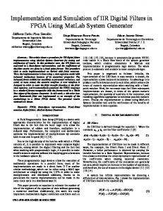
Figure 1. AADS interfaces with flight-like data structures used for simulation integration: (1a) spacecraft inputs to AADS which will or may change each AADS call, (1b) spacecraft inputs to AADS which are not likely to change during the aerobraking mission, (2) AADS outputs to the spacecraft, and (3) intra-AADS.
Program to Optimize Simulated Trajectories II (POST2) The Program to Optimize Simulated Trajectories II (POST2) is a generalized point mass, rigid body, discrete parameter targeting and optimization trajectory simulation program based on the POST software initially developed in the 1970’s by NASA Langley Research Center in partnership with the Martin Marietta Co.8, 9 Throughout the years, POST has been continually upgraded and modified to support a large variety of aerospace vehicle development and mission flight operations through trajectory simulation, flight dynamics analyses, vehicle system development and evaluation, as well as integrated system performance assessments. The program was significantly improved with additional capabilities added in the area of vehicle modeling, trajectory simulation, and targeting and optimization. Three and six degree-of-freedom (DOF) versions of POST, which optimized and targeted ascent, entry, or orbital trajectories, have been available since the 1980’s.
4
POST2 development began in the mid-1990’s in an effort to update the internal software architecture and expand the modeling capability of the original POST computer code. POST2 has been used successfully to solve a wide variety of atmospheric ascent and re-entry problems, as well as exo-atmospheric orbital transfer problems. The versatility of the program is evidenced by its multiple vehicle, multiple phase simulation capability that features generalized planet and vehicle models. POST2 also contains many basic models (such as atmosphere, gravity, propulsion and navigation system models) while maintaining modularity in the code structure. As a result, the user has substantial flexibility to modify existing models, or include mission specific models of very high fidelity, such as vehicle specific aerodynamic data, planetary (e.g. gravity) and atmosphere models, vehicle and sensor models, and even onboard flight/mission specific software. POST2 has become an industry standard trajectory simulation and optimization tool that has been transferred to hundreds of organizations throughout government, industry, and academia, where it is used to evaluate, design, develop, test, and operate numerous current and future aerospace systems. SIMULATION ENVIRONMENT AND MODELS AADS and POST2 Integration Because of the high level of flexibility and modularity of POST2 described above, it was possible to integrate the AADS code with POST2 in a way that is very “flight-like”. In this simulation environment, POST2 takes on the role of the spacecraft (and physical environment), where AADS is then executed through the POST2 flight software interface, in much the same way it would be implemented onboard the spacecraft. The interface data structures described earlier are created on the spacecraft/POST2 side and passed into AADS. As would be the case onboard the spacecraft, the AADS code has no other connection to POST2 or the “outside world”, and vice versa, except through the data structure interface. Once integrated, the POST2 and AADS code are compiled into a single executable which is then run using the POST2 user interface. As an integrated simulation environment, it is necessary for POST2 to take on many of the responsibilities of the spacecraft, namely the generation and passing of critical data needed by AADS, including: 1. 10 Hz sensed acceleration vector during both maneuvers and atmospheric passes for the Ephemeris Estimator. 2. 1 Hz sensed acceleration and quaternion (inertial to rotating body frame) during the atmospheric passes for the Atmosphere Estimator. 3. Planetary ephemeris data (e.g. central body, Sun) over the time period of interest for the Ephemeris Estimator The data are collected during the trajectory simulation, saved in the appropriate AADS interface structure data arrays, and then passed to AADS when it is called. In actual flight, the acceleration data would be collected from the spacecraft IMU, processed, and stored in the data structures for AADS usage. The planetary ephemeris data would likely be uploaded to the spacecraft from the ground, possibly updated at some interval, and then sent to the AADS when called. Other Models and Simulation Inputs As previously described, POST2 has many built-in planetary and environment models, but it also has the capability to integrate mission specific models. For the AADS POST2 simulation environment, this was done in several areas including gravity, atmosphere, and spacecraft aerodynamics. Additional models were also developed and integrated into the POST2 simulation environment, including solar radiation pressure and 3rd body gravitational effect.
5
AADS PERFORMANCE FOR MARS Mission Runout In order to assess the operational advantages and estimate performance of the AADS software, a comparison must ultimately be made with an aerobraking mission runout. POST2 (without AADS integrated) was used to simulate this mission runout in an application at Mars. For this analysis, an initial orbital state was selected from the Mars Reconnaissance Orbiter (MRO) flight profile after the “walk-in” phase of the aerobraking mission was completed. A generalized spacecraft geometry and mass properties were also used as simulation inputs. In addition, the MarsGRAM-2010 atmosphere model10 was integrated with POST2, along with an 85x85 Mars gravity field and an MRO aerodynamics model. A full aerobraking mission was then simulated, using a freestream heat rate corridor, until the apoapsis altitude is brought to 450 km. In addition, the Mars mission runout maneuvers were constrained to occur no more frequently than once a week. For aerobraking at Mars, the estimated freestream heating rate, given by:
1 qÝ V 3 2
(1)
where qÝis the freestream heating rate, is the atmospheric density, and V is the spacecraft speed, is used as the operational corridor to which the spacecraft must be kept during the main aerobraking phase. For this analysis, the corridor was set to 0.11 to 0.17 W/cm2. Since maneuvers were constrained to once a week, it was necessary to bias the target within this corridor as a function of orbit period: 80% for orbit periods greater than 10.5 hrs, 70% for orbit periods between 10.5 and 2.5 hours, and 50% for orbit periods less than 2.5 hrs.
Figure 2. Aerobraking mission runout: nominal mission operations corridor performance
6
Figure 2 shows the operational corridor performance for the mission runout simulation. As noted earlier, the corridor target was varied as a function of orbit period in order to ensure the corridor was maintained (upper limit not exceeded) throughout the aerobraking mission while constraining maneuvers to no more frequently than once a week. The corridor performance for the AADS is expected to be similar to that of the mission runout. However, with the added advantage of a fixed corridor target and maneuvers allowed on each orbit, the AADS system should complete the aerobraking mission much more efficiently (i.e. in a shorter amount of time), by doing a much better job of remaining within the corridor. A representative operational immediate action line is also shown to provide context as to how the corridor would be established to provide sufficient margins during the main aerobraking phase. AADS Performance With the AADS software successfully integrated into the POST2 simulation environment, AADS performance has been assessed for application at Mars. The AADS POST2 simulation utilizes the same atmosphere, gravity, and aerodynamics models as the mission runout11. The initial state for the AADS simulation, however, is extracted from the mission runout results. The apoapsis state of the 7th orbit of the mission runout is used in order to allow for data from the first 7 atmospheric passes to be used to build the atmosphere archive needed by the Atmosphere Estimator. (During actual operations, this archive would likely be constructed during the “walk-in” phase, while there is still ground interaction, prior to initiation of the AADS system.) The same operational corridor as the mission runout is also used for the AADS simulation; however, the target is fixed at 50% of the corridor for the duration of the aerobraking mission. In addition, since this system is fully autonomous, maneuvers are allowed to occur at any apoapsis. The Ephemeris Estimator performance can be assessed by examining how well the AADS module estimates the current periapsis conditions as compared to those in POST2. Figure 3 (a and b) illustrates this performance, showing the estimated differences in terms of periapsis time and altitude. At the start of the simulation, when the Ephemeris Estimator is initialized with the POST2 state, the performance is quite good, showing excellent agreement (sub-second and meter level) between the Ephemeris Estimator and POST2 estimates. As time progresses, drifting in the Ephemeris Estimator propagation, as well as a build up of error from the lack of precision (i.e. frequency) in the acceleration data provided from the spacecraft, causes the Ephemeris Estimator estimates to diverge (10-20 seconds and 100’s of meters). In order to mitigate this during implementation in flight, an initialization state update would be provided to the Ephemeris Estimator at some regular interval. For this AADS simulation, this was done once per week. As the mission progresses and the orbit period reduces, the Ephemeris Estimator propagation relies more heavily on acceleration data as the atmospheric passes become longer and more frequent, resulting in increased divergence due to the increased atmospheric pass duration and the number of orbits between Ephemeris Estimator initialization state updates. This is evident in the more rapid fall-off of the Ephemeris Estimator estimates towards the end of the aerobraking mission. Increased acceleration data rates (e.g. 100 Hz) have been shown to greatly increase the performance at these later mission times (Figure 3c). However, the impact on the spacecraft resources to save this amount of data is significant. Another option would be to increase the frequency of the initialization state updates to minimize the Ephemeris Estimator divergence (Figure 3d). However, the time where this performance drop-off is most likely to occur is after the main aerobraking phase would end. The mission would have transitioned into the lifetime constraint or orbit safety phase, where AADS would not be utilized. Regardless, preliminary results show overall the Ephemeris Estimator performance shown here is sufficient for successful AADS operation over the main aerobraking phase of the mission.
7
(a)
(b)
(c)
(d)
Figure 3. AADS Ephemeris Estimator performance: (a) current periapsis time, (b) current periapsis altitude, (c) current periapsis time using 100 Hz acceleration data, and (d) current periapsis time for state updates every 3 days.
(a)
(b)
Figure 4. AADS Atmosphere Estimator performance: (a) periapsis atmospheric density, (b) periapsis atmospheric scale height
8
The Atmosphere Estimator performance can be assessed by comparing the density and scale height estimates (based on a simple exponential atmosphere) for periapsis against those from the MarsGRAM-2010 atmosphere model, as shown in Figure 4. The density prediction is generally within 10% and the scale height within 1 km (~14%) of the MarsGRAM-2010 model. Efforts to tune the Atmosphere Estimator can provide additional improvements. However, the current Atmosphere Estimator performance appears to be sufficient for successful AADS operation. The Maneuver Estimator and AADS performance are highly coupled and can be assessed by determining how well the spacecraft remains within the desired operational corridor. Data from the Ephemeris and Atmosphere Estimators are used to estimate the freestream heating rate at periapsis during the next atmospheric pass. If the estimate is outside of the operational corridor, a maneuver is calculated such that the heating rate for the next atmospheric pass is at the target location within the corridor (50%, or 0.14 W/cm2). This is done by first calculating a desired change in altitude using:
h H s ln(
qÝ desired ) H s ln( desired ) predicted qÝpredicted
(2)
where Hs is the predicted atmospheric scale height. This change in altitude is added to the current orbit semi-major axis and a new velocity at apoapsis is determined. The difference between this new apoapsis velocity and the current estimate of the apoapsis velocity is the desired maneuver magnitude. This value is positive for a periapsis raise (decrease freestream heating rate) and negative for a periapsis lowering (increase freestream heating rate). The maneuver direction is estimated to be in the direction of the pre-maneuver velocity vector at apoapsis. Since these maneuvers are typically small (< 0.5 m/s), this assumption works well, even when considering a finite burn. (The mission runout simulation calculates required maneuvers in much the same way.)
Figure 5. AADS: nominal mission operations corridor performance
9
A summary of the AADS performance for the Mars aerobraking mission simulation, in terms of how well the spacecraft stays within the mission operations corridor, is provided in Figure 5. It clearly shows that the AADS system does a successful job of keeping the spacecraft within the specified corridor. Figure 5 also illustrates the difference between the AADS predicted freestream heating rate and the actual, which is mainly driven by the difference between the Atmosphere Estimator density and scale height estimates from the MarsGRAM-2010 atmosphere model. Figure 5 clearly shows that the AADS systems does a very good job of keeping the spacecraft within the operational corridor. As previously discussed, at the very end of the aerobraking mission, the very long atmospheric passes emphasizes the effects of acceleration data precision on the Ephemeris Estimator (and Atmosphere Estimator) performance. It is important to remember that in flight operations, AADS functions would very likely terminate before this threshold is reached when the aerobraking mission transitions from the main phase when orbit period reduction is the focus, to the next phase when orbit safety / lifetime is of greatest concern.
(a)
(b)
Figure 6. AADS constrained mission operations corridor performance: (a) fixed at nominal corridor upper limit, (b) fixed at nominal corridor lower limit Table 1. Summary of AADS performance for runs using the nominal operational corridor, a corridor constrained to the nominal corridor upper limit, and one to the nominal corridor lower limit.
Nominal
Upper Limit
Lower Limit
aerobraking duration (days)
155.0
125.1
184.9
total ∆v (m/s)
9.5
31.5
36.2
no. of maneuvers
39
325
450
As discussed earlier, changing the corridor limits can have an effect on the aerobraking mission duration. To illustrate this, the AADS aerobraking mission was simulated using a very tight operational corridor (0.02 W/cm2 in width) centered at the corridor upper limit (0.17 W/cm2) and again at the corridor lower limit (0.11 W/cm2). Figure 6 illustrates the corridor performance for these cases. A summary of the mission performance for all AADS mission simulations is provided in Table 1. Again, the accuracy at which AADS can maintain such a tight operational corridor will be driven by accuracy in the predicted freestream heating rate. Any improvements in the
10
Atmosphere Estimator (or Ephemeris Estimator) will narrow the spread between the predicted and actual, improve the required maneuver estimate to reach the target in the corridor, and thus improve even further the overall corridor performance. AADS Comparisons to Mission Runout With simulations complete for both the Mars aerobraking mission runout and AADS implementation, it is now possible to compare the system performance between these two analyses. Figure 7 provides a comparison of the aerobraking mission profile of both the AADS and mission runout simulations, including the difference between the aerobraking “glide slope” (orbit period versus time), as well as a comparison of the commanded maneuvers, orbit periapsis altitudes, and periapsis locations (areocentric latitude) as a function of time. Table 2 also provides a comparison of the summary mission performance for each simulation.
(a)
(b)
(c)
(d)
Figure 7. AADS versus mission runout comparisons: (a) apoapsis altitude “glide slope”, (b) orbit period, (c) periapsis altitude, (d) periapsis areocentric latitude
These results show the efficiency of the AADS system, not only in terms of ground operations, but also with respect to completing the aerobraking mission. It should be noted that although maneuvers were allowed at any apoapsis for the AADS simulation, in actual flight operations, this may not be desired or allowed. Practical limits may exist on the spacecraft propulsions system in both how frequently maneuvers can be performed, as well as the magnitude of those maneuvers.
11
Clearly, for very small maneuvers, constraints may require the AADS system to postpone execution until a point at which the spacecraft drifts sufficiently outside of the operational corridor in order to meet any burn requirements. Table 2. Summary of AADS performance compared to Mars mission runout.
Nominal
Runout
aerobraking duration (days)
155.0
177.7
total ∆v (m/s)
9.5
9.6
no. of maneuvers
39
22
CONCLUSION Summary of Results The results shown here indicate that the AADS system should provide sufficient performance to successfully complete an aerobraking mission at Mars. By creating code and integrating it in a “flight-like” manner, there is high confidence that the performance level will be maintained once converted to flight software and executed on flight hardware or onboard a spacecraft. At the Applied Physics Laboratory of John Hopkins University, AADS work includes the development of a High Fidelity Simulation using flight hardware and a modified MESSENGER spacecraft testbed to run and evaluate the AADS system12. Even at this early development stage, these results show that much of the ground operations functions can be performed autonomously onboard while still ensuring spacecraft safety. With this realized, the resource savings for future aerobraking missions utilizing an autonomous system such as AADS (in the form of reduced ground staff, reduced DSN coverage, and even possibly reduced operations time), can be dramatic. Moving Forward / Future Work As indicated earlier, the development of the AADS system is still ongoing. There is additional work to be done to ensure smooth transition to flight software, as well as verify application at other bodies of interest. We are only nearing the completion of Phase 1 of the AADS development. Phase 2 is expected to begin once nominal testing is completed in Phase 1. The results presented were based on nominal / non-perturbed environments. Now that the AADS system has been shown to work well under nominal conditions, the next step is to verify it can still perform adequately in off-nominal situations. This will required continued stress testing of the simulation and AADS code to ensure successful operation under all conceivable environments and conditions. One example of where this will clearly be of great importance is the POST2 atmosphere model. Obviously, atmospheric conditions very rarely conform to some nominal state, particularly when considering a pass through the atmosphere across a wide swath over a period of several minutes. Understanding the effects of a perturbed atmosphere will be crucial to ensuring the AADS system will still perform well under “real-life” flight conditions. Additional spacecraft models, such as an IMU, can also be added to the POST2 simulation to provide more realistic acceleration data containing expected in-flight noise levels. In addition to verifying the AADS system performance under more flight-like conditions, the system must also perform when aerobraking at bodies other than Mars. Continued work will include simulation of aerobraking missions at both Venus and Titan. At Venus, where solar radia-
12
tion pressure and 3rd body effects from the Sun will become significant, and heating from the thick atmosphere a greater concern, thermal models13 will be used to estimate the spacecraft (e.g. solar array) temperature that will act as the operational corridor during the aerobraking mission. At Titan, when Saturn 3rd body gravitational effects dominate, dynamic pressure will be used as the operational corridor throughout aerobraking. With solar radiation pressure and 3rd body gravitational effects already modeled, the AADS code is quite versatile to these various conditions and options. Only small changes in the Atmosphere Estimator are required to account for the differences in the atmospheres at Mars, Venus, and Titan. The Ephemeris Estimator would only need to account for the differences in the gravity field and other body characteristics (already provided by the spacecraft through the interface structure). Finally, updates to the models used to determine where the spacecraft is with respect to the desired operational corridor are all that remains to create versions of the AADS system that will successfully, safely, and autonomously execute a full aerobraking mission at any of these destinations. ACKNOWLEDGMENTS This work is sponsored by the NASA Engineering and Safety Center. Their assessment can be found in the final report NESC-RP-09-00605 due in November 2011. The authors would also like to recognize David Skinner (Kinetx, Inc.) and Robert Tolson (National Institute of Aerospace) for the development of the Ephemeris Estimator and the Atmosphere Estimator respectively, and for their tremendous support in the integration and testing of these models into the POST2-AADS simulation. Special thanks goes the Chris Pastore (Analytical Mechanics Associates) for his support in the development and integration of the POST2-AADS simulation. REFERENCES 1
Jill L. Hannah, Robert H. Tolson, “Approaches to Autonomous Aerobraking at Mars.” The Journal of the Astronautical Sciences, Volume 50, No. 2, April-June 2002. 2
Daniel T. Lyons, “Aerobraking Automation Options.” AAS-01-385, AAS/AIAA Astrodynamics Specialist Conference, Quebec City, CA, 2001.
3
David A. Spencer, et al., “Aerobraking Cost and Risk Decisions.” Journal of Spacecraft and Rockets, Volume 44, No. 6, November-December 2007. 4
J.L. Prince H., S. A. Striepe, “NASA Langley Simulation Capabilities for the Mars Reconnaissance Orbiter”, AAS/AIAA Space Flight Mechanics Conference, Copper Mountain, Colorado, January 23-27, 2005. 5 Jill L. Prince, Dan Murri, “Autonomous Aerobraking: A Design, Development, and Feasibility Study.” AAS 11-473, AAS/AIAA Astrodynamics Specialist Conference, Girdwood, AK, 2011. 6
David L. Skinner, Robert W. Maddock, “Autonomous Aerobraking Ephemeris Estimator.” AAS 11-472, AAS/AIAA Astrodynamics Specialist Conference, Girdwood, AK, 2011. 7
Robert H. Tolson, Jill L. Prince, “Onboard Atmospheric Modeling and Prediction for Autonomous Aerobraking Missions.” AAS 11-477, AAS/AIAA Astrodynamics Specialist Conference, Girdwood, AK, 2011. 8 S.A. Striepe et al., “Program To Optimize Simulated Trajectories (POST II): Volume 2, Utilization Manual.” Martin Marietta Corporation, 2004. 9
G. L. Brauer et al., “Program To Optimize Simulated Trajectories (POST): Volume 1, Formulation Manual.” Martin Marietta Corporation, 1990.
10
Hilary L. Justh et al., “The Next Generation of Mars-GRAM and Its Role in the Autonomous Aerobraking Development Plan.” AAS 11-478, AAS/AIAA Astrodynamics Specialist Conference, Girdwood, AK, 2011.
11
Autonomous Aerobraking Planetary Constants and Models, v0.06, 9 June 2011, project document.
13
12
David Carrelli et al., “Autonomous Aerobraking Algorithm Testing In Flight Software Simulation Environment.” AAS 11-471, AAS/AIAA Astrodynamics Specialist Conference, Girdwood, AK, 2011.
13
John A. Dec et al., “Autonomous Aerobraking: Thermal Analysis and Response Surface Development.” AAS 11474, AAS/AIAA Astrodynamics Specialist Conference, Girdwood, AK, 2011.
14