Impllementation Issues of a Frequency Hopped Modem M.P. Fitton, D.J. Purle, M.A. Beach, and J.P. McGeehan Centre for Communications Research, University of Bristol Queens Building, University Walk Bristol. BS8 l T R , United Kingdom Tel: f 4 4 117 928 7740, Fax: +44 117 925 5265 e-mail:
[email protected]
Abstract Investigations into Code Division Multiple Access (CDMA) have shown that Frequency Hopping (FH) possesses many of the advantages claimed by Direct Sequence (DS) spread spectrum techniques [l].This paper investigates the theoretical and practical implementation issues associated withi designing a FH modem. The criteria which are explored include areas which are specifically associated with the frequency hopping nature of the modem, such as the the hopping synthesizer, hop duration, and hop bin separation. Furthermore, consideration is made of the impact of frequency hopping on more general design issues, such as coding, modulation, and multiple access. Work at the Centre for Communications Research (CCR) in Bristol has been carried out t o develop a practical implementation of at prototype frequency hopped modem. The paper includes the modem design, and preliminary performance in an aldditive white noise channel.
1 Intro(duction The evaluatioin of both TDMA and CDMA air interface techniques for third generation wireless networks is now gathering considerable momentum. The recent allocation of spectrum to personal communications systems (PCS) by the Federal Communications Commission (FCC) in the US can only tencourage this trend. This is also evident in Europe with numerous activities funded under both E.C. RACE and UK DTI/EPSRC LINK initiatives addressing UMTS. Recent research considering CDMA has been largely aimed towards the use of the Direct Sequence (DS) spreading technique, and consequently commercial applications of Frequency Hopping (FH) have received less attention. Analytical work at Bristol [l]and elsewhere [2] has shown that the claimed advantages of DS can also apply to FH CDMA networks when evaluating the relative performance of low and medium rate data bearers in both PCS and UMTS like environments. Frequency holpping systems employ a conventional modem structure, however the R F carrier frequency is not fixed,
0-7803-2742-3795 $4.00 0 1995 IEEE
and the modem will hop between a number of frequencies in a predetermined pattern. Similar to Direct Sequence, using frequency hopping spread spectrum (FH SS) affords inherent frequency diversity in transmission. Even if one or more of the carriers are corrupted due to multipath effects, no outage will result providelcl the majority of the bearers provide perfect transmission. Furthermore, FH provides resilience to interference, since a given interferer will only corrupt one packet before the modem hops away to another frequency. This interference diversity is of particular use in the multi-user scenario, where it can be exploited to reduce the effects of inter-cell interference. Since a frequency hopping system will hop to different frequencies, it does not require contiguous spectrum, unlike TDMA and DS CDMA. This is of particular advantage in certain cases when licensing does not permit the use of contiguous spectrum, such a s the FCC recommendations on Special Mobile Radio Services. Previous propagation work :3] and computer simulations [2] of Slow Frequency Hopping CDMA have shown this technique to have considera,ble potential. This research has indicated the need to evaluate both theoretical and practical design issues related to implementing a FH transmitter and receiver for use in the mobile channel. The use of frequency hopping in the modem introduces complexities which are not necessarily present in other types of air interface techniques, including the choice of hopping generator, hop rate, and hop separation. Furthermore, the FH nature of the modem impacts on other design issues, such as coding, moduhtion scheme, multiple access, and services offered. This paper attempts to address these considerations, by exploring the options available at each stage of the design. In particular this investigation is biased towards a mobile comniunication system with low to medium data rate capability, for application in the PCStype field. Work at the Centre for Communications Research (CCR) in Bristol has been undertaken to develop a practical implementation of a narrowband frequency hopping modem. This prototype has been constructed employing rI4-DQPSK modulation and direct digital synthesis for hopped carrier generation, allowing a capability for con-
125
2.3
ventional voice transmission. The preliminary performance of the modem is validated using both back-to-back testing and transmission through a n additive white noise channel.
The traditional modulation scheme for FH systems tjends to be M-ary Frequency Shift Keying (FSK). However, there is also a great deal of interest in linear modulation [a].Since linear modulation can utilises both amplitude and phase information to convey message information, the signal bandwidth required is reduced. The spectral occupancy can be reduced still further by employing pulse shaping.
Design Issues 2.1
Services Offered
Whether the FH receiver is coherent or differential is also source of some controversy. Coherent detection will obviously improve system performance, but creates the problem of recovering carrier phase. Even though it can be assumed that phase coherence will be maintained during the hop period, it is almost impossible to track the phase across hop boundaries due to the effects of the hopping synthesizer and the channel itself. The need for a small, power efficient handset in PCS would seem to preclude the complexities of coherent reception, at least a t the present time. Using a differential system considerably eases the complexities of implementing the FH receiver.
The services which are offered by the frequency hopping modem will greatly impact on other system criteria. The distinction between the requirements for data and those for voice traffic mainly affect the choice of coding and interleaving (see section 2.5). Unlike voice communications. data traffic does not have the same stringent limitations imposed on interleaving depth. In general, data communication will require much lower bit error rates than those that are acceptable with voice (a BER in the order of 10V6 as compared to lop3). However, it would be possible for a data modem to employ Automatic Repeat Request (ARQ) protocols rather than Forward Error Correcting (FEC) codes. Investigations have shown that ARQ protocols do not exploit the randomising effects of frequency hopping as effectively as FEC schemes. Consequently, using FEC coding would appear to limit a FH system to predominantly speech, with limited data transmission capability.
2.2
Modulation Scheme
In addition, the choice of linear modulation scheme is quite complex. The use of certain modulation schemes, such as offset,-QPSK and ~ l 4 - s h i f t e dQPSK, is beneficial in reducing the stringent linearity requirements of the power amplifier. This means that the amplifier can be operated a t a more power efficient level, for specified levels of in-band and out-of-band interference. Alternatively, multi-level schemes could be employed, in order to improve bandwidth efficiency at the expense of performance in noise. One such suitable modulation scheme is known as 16-level Amplitude and Phase Shift Keying (16APSK) and has been investigated at the University of Bristol [4].
Hopping Synthesizer
The hopping synthesizer is used to produce a signal a t a number of different frequencies over the band of interest, and furthermore must be capable of hopping at the required rate. The hopped signal can either occupy a section of contiguous spectrum centered on a particular frequency. or may be sub-divided further due to the necessities of the licensing. A number of different methods can be used to synthesize the required hopping signal, wit,h the two main areas of interest being phase locked loop (PLL) and Direct Digital Synthesizer (DDS) techniques.
2.4
Hopping Characteristics
The main hopping characteristics associated with the FH modem are the hop rate, and hop bin separation. If the modem is not hopping a t a sufficiently high rate, the maximum interleaving depth for intelligible voice transmission \vi11 not allow for sufficiently uncorrelated symbols in the de-interleaved code word. This will then limit the effectiveness of any coding scheme that is employed.
The PLL approach produces a solution which is compact and power efficient, and therefore feasible to integrate into a handset. Recent development of conventional PLL methods into fractional-n techniques has resulted in improved settling times. DDS techniques can be used t o provide very fast settling times and fine frequency resolution, along with ease of integration and control. Unfortunately, current device technologies consume large amounts of power, are expensive, and often have a limited output frequency. Investigations into hybrid PLL/DDS systems have shown that they could combine the advantages of both systems.
Similarly, implementation of an efficient coding scheme requires careful study of hop bin separation (ie. the frequency separation between subsequent positions in the hopping pattern). If two adjacent hop periods are too close in frequency, the high degree of correlation between them will result in an impairment of the efficiency of the coding (since the symbols in the codeword will not be independent of each other). This necessitates a separation of subsequent hops which is greater than the coherence
126
Paramet er
bandwidth of the channel. This can be accomplished by careful choice d hop bin separation and hop pattern [ 5 ] .
2.5
Specification
U
Coding and Interleaving
The issue of coding in a frequency hopping channel is one of great importance, since without interleaving and coding a SFH system will have no performance advantage over a conventionall narrowband modem. The action of interleaving the co.nstituent symbols of a given codeword over a number of different hop frames will result in effectively randomising the fading characteristic experienced by the codeword. Although a coding scheme employed will become more eflicient as the code length is increased, the necessity of produce intelligible speech limits interleaving depth t o the order of 40 m s . Furthermore, the type of coding itself will have great impact on the overall system performance. Conventional codes, such as BCH or halfhate convolutional codes, can be utilised with reasonable success, provided the code length (or constraint length) are suitable for the interleaving depth. Other methods t o improve effectiveness do exist, including schemes which recover side information from the received signal. The technique of developing channel information from test symbols, or concatenated coding, can be easily incorporated into existing system design, and is more straightforward to implement [6]. The side information can be used t o detect errors and mark them as erasures, thus improving the efficiency of the final decoding. One possible scheme is shown in figure 1. The inner code (such as BCH) processes the received data before deinterleaving, marking the entire block as an erasure if any errors are detected. De-interleaving then occurs, and the outer code is used on the remaining errors and erasures. super-channcl . c I
--
super-coder (nN, I R )
-
Table 1: FH Modem Specifications adjacent cells will minimise inter-cell interference. Consequently it would be possible t o approach a one-cell repeat pattern, which greatly enhances the system's performance with respect to traditional FDMA systems.
3
Hardware Implementation
This section describes the hardware which was implemented in the development of a prototype frequency hopping modem. The design itself is based on the criteria set out in previous section, and demonstrates the issues and compromises which relate to practical implementation. The aim of the prototype development was to develop a system which could transmit voice data over a mobile channel. The modulation scheme employed is that of 7r/4 shifted differential QPSK, due t o ease of reception and noise performance (as detailed in section 2.3). The system specifications are shown in table 1.
3.1
Modulator DSX'
The modulator is implemented using a digital signal processor (DSP) to carry out interfacing, modulation and root-raised cosine filtering of the signal. By operating the modulator at 2 samples per symbol, the processing required was not particularly complex and permitted the use of a relatively simple (and cheap) DSP device.
u u supcr-decoder
Figure 1: Concatenated Coding Scheme
3.2 2.6
Mukiple Access
One major advantage of a Frequency Hopping system is that the judicious choice of hopping pattern will result in an efficient Multiple Access. Using mutually orthogonal codes to gover-nthe hopping pattern of all users in one cell will result in no intra-cell interference [7]. Furthermore, using codes with minimal cross-correlation properties for
Demodulator DSP
Implementation of the 7r/4 IIQPSK demodulator was more complex than the relatively simple task of designing the modulator. The receiver samples the input signal at a relatively slow rate of approximately 4 samples per symbol, due to the upper limit of the DSP clocking rate. One of the main problems !involves recovering the symbol timing from the incoming signal. The algorithm used is
127
based on the ‘spectral-line’ technique [8], which is implemented on-board the DSP. The baseband signal is passed through a non-linearity (in this case a squaring operation) to produce a spectral line at the symbol rate. This signal is then band-pass filtered, and used t o drive a DSP implemented phase-locked loop. The use of the phase-locked loop ensures that the system is more resilient to noise.
of one sample in any one hop frame. The main drawback with this implementation of a hop clock recovery circuit is that the frequency discriminator required a channel spacing of at least 100 kHz for reasonable performance. Operation of this system at an IF, rather than baseband would result in improvement in both the timing uncertainty and the minimum channel spacing. To date, this hop clock recovery system has not been integrated with the remaining receiver hardware.
The recovered timing signal is then used t o calculate the ideal sampling point. To provide a greater degree of resolution in the decoded signal, the received waveform is interpolated up to 32 samples per symbol. Conventionally this interpolation would also result in a large increase in the processing required t o perform the match filtering and the interpolation filtering. However, to make a decision on the received symbol only requires a single sample, corresponding t o the ideal sampling point. Consequently, the filtering need only be carried out once per symbol [9], thus reducing processing overhead for both filtering operations.
3.3
4
Results
The performance of the frequency hopping modem is validated using an additive white Gaussian noise (AWGN) channel, and comparing the bit error rate performance with theoretical results. The modem was also tested backto-back t o determine the irreducible error rate, and no errors where observed when approximately lo9 bits were transmitted.
Hopping Synthesizer
The prototype modem synthesizer was implemented using direct digital frequency synthesis. This technique has certain disadvantages, namely high power consumption and limited frequency output. However, control of the DDS device is very simple, via a interface connecting directly t o a DSP. In addition, a dual DDS was used to provide frequency quadrature, allowing the baseband signal to be converted directly to an IF without the need for other complexities such as a Hilbert Transform.
3.4
Acquisition and Tracking
The modem is envisaged t o be operating in a multipleaccess scheme where users in the same cell are synchronised, each having a different offset in the same hopping code. Provided other cells operate with an orthogonal code, the requirements specified in section 2.6 are fulfilled The demodulator DSP can then implement a ‘camp and wait’ algorithm, where the receiver will only hop to the next hop frequency in the sequence when it detects energy at its current frequency. By requiring a number of consecutive hops to be successfully detected, the system is made more tolerant to interference from stray users in other cells, as an orthogonal code is very unlikely to give high correlation with the wanted sequence over several hops. An experimental, analogue version of the early-late tracking system [lo] was implemented in hardware using a frequency discriminator and some associated logic functions. The system was shown t o recover the frequency of the hop clock perfectly, however there still existed a degree of uncertainty in the time resolution of the signal, which translated as variation of 3=20ps, which could result in the loss
128
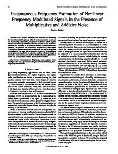
Figure 2: BER Performance of Modem at IF of 5 MHz The modem was tested in a number of different configurations, in order to determine performance with and without frequency hopping. Figure 2 shows the performance of the 7r/4 DQPSK modem as a conventional narrowband system, operating at an IF of 5 MHz (ie. with no frequency hopping). The results produced show only limited degradation as compared t o the theoretical results, with spread of points well within the bounds of experimental erroi due to difficulty of measuring signal-to-noise ratio. The main reason for any degradation is due sub-optimal sampling points resulting from inaccuracies in timing point interpolation.
The last set of results included (figure 3) illustrate the performance of the full frequency hopping system, operating with 20 hop frequencies over a 2 MHz hopping bandwidth.
6
Acknowledgements
The authors would like t o thank the University of Bristol for their financial support, and the Centre for Communication Research and Prof. J.P.McGeehan for providing laboratory facilities and a marvellous working environment. In addition, the authors gratefully acknowledge the invaluable assistance of‘ Dr. A.R.Nix, Dr. T.Busby, Mr. R.J.Wilkinson, and Mr. A.Mansel1 in developing the modem. le 005
~
References 4
5
6
7
x
9
1 O 1 1 1 2 l i
S. Swales, T. Bushy, D. F’urle, M. Beach, and J. McGeehan, “A comparison of CDMA techniques for third generation mobile radio systems,” in I E E E 43rd Vehicular Technology Conference, pp. 424-427, May 1993. N.Livneh, R. Meidan, M . Ritz, and G. Silhershatz, “Frequency hopping CDMA for future cellular radio,” in I E E E 42nd Vehicular Technology Conference, pp. 400-404, May 1992.
Figure 3: BER Performance of Hopped Modem
The results show reasonable performance of the overall frequency hopping system, although the configuration has synchronised hopping of transmitter and receiver.
D. Purle, S. Swales, M. Beach, and J. McGeehan, “Propagation characteristics of a frequency hopped channel,” I E E 8th International Coilference on Antennas and Propagation, pp. 819-824, October 1993. A. Nix, R. Castle, and J. McGeehan, “The application of 16APSK to mobile fading channels,” in I E E 6th International Conference on Mobile Radio and Personal Communications, December 1991.
Conclusions and Future Work This paper set out t o highlight some of the practical and theoretical problems associated with the construction of a frequency hopped modem. This was further illustrated by the construction of a prototype frequency hopping modem at the University of Bristol.
M. Fitton, D. Purle, and IVI. Beach, “The impact of sytem bandwidth on a frequency hopped channel.” to he puhlished in IEE 10th International Conference on Antennas and Propagation, April 1!)95.
The current modem operates with a synchronised hop clock for transmitter and receiver. Obviously, for full functionality it would be necessary for the transmitter and receiver to be able to ‘stand alone’, thus requiring integration of a tracking circuit into the overall system.
M. Pursley, “New approaches for error correction in frequency-hop spread-spectrum receivers,” in IEEE 2nd International Symposium on Spread Spectrum Techniques and Applications, pp. 2-10, November 1992. D. Verhulst, M. Mouly, and J. Szpirglas, “Slow frequency hopping multiple access for digital cellular radiotelephone,” I E E E Journal on Selected Areas in Communications, vol. SAC2, pp. 179-190, July 1984.
When tested in an additive white Gaussian channel, the prototype modem produced results which agreed well with theoretical bit error rate characteristics. However, to accurately test t,he prototype modem in realistic conditions would require incorporating fading characteristics into the channel model. It would then be possible characterise the modem much more thoroughly, including the effects of coding and performance in the multi-user scenario. The final stage in the development would be to convert the signal up to RF, and carry out field trials with the modem.
L. Franks, “Carrier and hit synchronisation in data communications a tutorial review,” I E E E Transactions on Communications, vol. COM-28, pp. 1107-1120, August 1980. P. Martin, Advanced Linear Modem Design for Narrowband Mobile Communications. University of Bristol: PhD thesis, February 1991. -
Overall, the work carried out has shown the feasibility of implementing a practical frequency hopped modem. Future work will aim to further validate the performance of the modem, as well as exploring other issues including multiple access and increasing bit rate to facilitate efficient data transmission.
129
R. Ziemer and R. Peterson, Digital Communications and Spread Spectrum Techniques. New York, USA: Macmillan, 1985.